Shunt Current Measuring up to 800A in the inverter - Semikron
Shunt Current Measuring up to 800A in the inverter - Semikron
Shunt Current Measuring up to 800A in the inverter - Semikron

Create successful ePaper yourself
Turn your PDF publications into a flip-book with our unique Google optimized e-Paper software.
20 INVERTER DESIGN www.isabellenhuette.de<br />
<strong>Shunt</strong> <strong>Current</strong> <strong>Measur<strong>in</strong>g</strong> <strong>up</strong> <strong>to</strong><br />
<strong>800A</strong> <strong>in</strong> <strong>the</strong> Inverter<br />
In 2005, Siemens Drive Technologies <strong>in</strong>troduced <strong>the</strong> first large <strong>in</strong>verter us<strong>in</strong>g shunts for phase current<br />
measur<strong>in</strong>g and brought it <strong>in</strong><strong>to</strong> series production. It wasn’t until recently that <strong>the</strong> power output was<br />
extended <strong>to</strong> 132kW with <strong>the</strong> new <strong>in</strong>verter SINAMICS G120 series. Back <strong>the</strong>n, <strong>the</strong> jo<strong>in</strong>t development<br />
between Siemens, <strong>Semikron</strong> and Isabellenhütte laid <strong>the</strong> foundations for be<strong>in</strong>g able <strong>to</strong> measure currents<br />
of <strong>up</strong> <strong>to</strong> <strong>800A</strong> <strong>to</strong>day. This article looks back at past events and takes a glimpse <strong>in</strong><strong>to</strong> <strong>the</strong> future: how was<br />
this technological change successful and what possibilities do future developments have <strong>to</strong> offer?<br />
Kurt Göpfrich, Hardware Manager for Power Electronics, Siemens Drive Technologies, Erlangen;<br />
Re<strong>in</strong>hard Stark, Sales Eng<strong>in</strong>eer, <strong>Semikron</strong> Elektronik, Nuremberg; and Ullrich Hetzler, Head of<br />
Research & Development, Isabellenhütte, Dillenburg, Germany<br />
There is noth<strong>in</strong>g revolutionary about <strong>the</strong><br />
current sens<strong>in</strong>g pr<strong>in</strong>ciple us<strong>in</strong>g a low value<br />
resis<strong>to</strong>r and an isolation amplifier. It was<br />
used for <strong>the</strong> first time by <strong>the</strong> first isolation<br />
amplifiers from HP and Siemens <strong>in</strong> electric<br />
drive systems 15 years ago. Now, <strong>the</strong>re are<br />
systems available from numerous<br />
providers, which represent <strong>in</strong>terest<strong>in</strong>g<br />
alternatives <strong>in</strong> terms of both technical<br />
requirements and cost, and that offer<br />
significantly better cost performance ratio<br />
than conventional solutions with current<br />
transformers.<br />
Demand for more power as well as<br />
<strong>in</strong>creased accuracy, lower construction<br />
and mount<strong>in</strong>g space, cost reductions and<br />
technological <strong>in</strong>novation led us <strong>to</strong> focus<br />
aga<strong>in</strong> on alternatives <strong>to</strong> conventional<br />
current transformers and develop an<br />
<strong>in</strong>tegrated and modular concept. This<br />
concept can be adapted <strong>to</strong> all <strong>in</strong>verters <strong>in</strong><br />
<strong>the</strong> entire power range from 100W <strong>to</strong><br />
100KW, both electrically and<br />
mechanically. The aim was <strong>to</strong> make<br />
technical improvements <strong>to</strong> <strong>the</strong> new<br />
SINAMICS G120, while at <strong>the</strong> same time<br />
<strong>in</strong>creas<strong>in</strong>g market acceptance by reduc<strong>in</strong>g<br />
prices.<br />
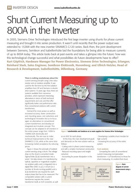
Figure 2 shows <strong>the</strong> pr<strong>in</strong>ciple of isolated<br />
current sens<strong>in</strong>g us<strong>in</strong>g a shunt. The voltage<br />
drop on <strong>the</strong> shunt is converted <strong>in</strong>side<br />
Sigma/Delta (/) transformers <strong>in</strong><strong>to</strong> a<br />
serial 1 bit data stream. It is transferred by<br />
optical, capacitive or magnetical co<strong>up</strong>lers<br />
via isolation paths and is <strong>in</strong>tegrated <strong>in</strong><strong>to</strong> a<br />
digital filter (ASIC or µC). A shunt (or a<br />
number of shunts runn<strong>in</strong>g parallel) and a<br />
/ transformer are required for each<br />
output phase that has <strong>to</strong> be measured. The<br />
comparable solution with a current<br />
transformer requires <strong>the</strong> current<br />
transformer itself, an A/D converter, as well<br />
Figure 1: Isabellenhütte and <strong>Semikron</strong> act as ma<strong>in</strong> s<strong>up</strong>pliers for Siemens Drive Technologies<br />
as an ASIC for each phase.<br />
At <strong>the</strong> time, <strong>the</strong> ma<strong>in</strong> development goals<br />
and demands on <strong>the</strong> new solution were as<br />
follows:<br />
• Cutt<strong>in</strong>g costs <strong>in</strong> phase current measur<strong>in</strong>g<br />
and with a simpler mechanical construction<br />
• Reduced mount<strong>in</strong>g space and weight<br />
reduction<br />
• Account<strong>in</strong>g for power dissipation <strong>in</strong> <strong>the</strong><br />
shunt<br />
• Develop<strong>in</strong>g a suitable shunt module for<br />
high currents<br />
• Increas<strong>in</strong>g <strong>the</strong> accuracy of <strong>the</strong> entire<br />
system<br />
Cost analysis<br />
Compar<strong>in</strong>g <strong>the</strong> costs of conventional<br />
current measur<strong>in</strong>g (compensation<br />
transformer + U/f transformer) <strong>to</strong> those for<br />
shunt measur<strong>in</strong>g, it is evident that shunt<br />
Figure 2: Basic<br />
diagram of current<br />
measurement us<strong>in</strong>g a<br />
shunt<br />
Issue 7 2009 Power Electronics Europe