Shunt Current Measuring up to 800A in the inverter - Semikron
Shunt Current Measuring up to 800A in the inverter - Semikron
Shunt Current Measuring up to 800A in the inverter - Semikron

Create successful ePaper yourself
Turn your PDF publications into a flip-book with our unique Google optimized e-Paper software.
ISSUE 7 – OCTOBER 2009<br />
INVERTER DESIGN<br />
<strong>Shunt</strong> <strong>Current</strong> <strong>Measur<strong>in</strong>g</strong> <strong>up</strong> <strong>to</strong><br />
<strong>800A</strong> <strong>in</strong> <strong>the</strong> Inverter<br />
Also <strong>in</strong>side this issue<br />
Op<strong>in</strong>ion | Market News | EPE 2009 Report | ECPE SiC Forum 2009<br />
Report | Power Modules | Power Semiconduc<strong>to</strong>rs | Power Device<br />
Reliability | Power for Traction | Au<strong>to</strong>motive Power | Products |<br />
Website Loca<strong>to</strong>r
20 INVERTER DESIGN www.isabellenhuette.de<br />
<strong>Shunt</strong> <strong>Current</strong> <strong>Measur<strong>in</strong>g</strong> <strong>up</strong> <strong>to</strong><br />
<strong>800A</strong> <strong>in</strong> <strong>the</strong> Inverter<br />
In 2005, Siemens Drive Technologies <strong>in</strong>troduced <strong>the</strong> first large <strong>in</strong>verter us<strong>in</strong>g shunts for phase current<br />
measur<strong>in</strong>g and brought it <strong>in</strong><strong>to</strong> series production. It wasn’t until recently that <strong>the</strong> power output was<br />
extended <strong>to</strong> 132kW with <strong>the</strong> new <strong>in</strong>verter SINAMICS G120 series. Back <strong>the</strong>n, <strong>the</strong> jo<strong>in</strong>t development<br />
between Siemens, <strong>Semikron</strong> and Isabellenhütte laid <strong>the</strong> foundations for be<strong>in</strong>g able <strong>to</strong> measure currents<br />
of <strong>up</strong> <strong>to</strong> <strong>800A</strong> <strong>to</strong>day. This article looks back at past events and takes a glimpse <strong>in</strong><strong>to</strong> <strong>the</strong> future: how was<br />
this technological change successful and what possibilities do future developments have <strong>to</strong> offer?<br />
Kurt Göpfrich, Hardware Manager for Power Electronics, Siemens Drive Technologies, Erlangen;<br />
Re<strong>in</strong>hard Stark, Sales Eng<strong>in</strong>eer, <strong>Semikron</strong> Elektronik, Nuremberg; and Ullrich Hetzler, Head of<br />
Research & Development, Isabellenhütte, Dillenburg, Germany<br />
There is noth<strong>in</strong>g revolutionary about <strong>the</strong><br />
current sens<strong>in</strong>g pr<strong>in</strong>ciple us<strong>in</strong>g a low value<br />
resis<strong>to</strong>r and an isolation amplifier. It was<br />
used for <strong>the</strong> first time by <strong>the</strong> first isolation<br />
amplifiers from HP and Siemens <strong>in</strong> electric<br />
drive systems 15 years ago. Now, <strong>the</strong>re are<br />
systems available from numerous<br />
providers, which represent <strong>in</strong>terest<strong>in</strong>g<br />
alternatives <strong>in</strong> terms of both technical<br />
requirements and cost, and that offer<br />
significantly better cost performance ratio<br />
than conventional solutions with current<br />
transformers.<br />
Demand for more power as well as<br />
<strong>in</strong>creased accuracy, lower construction<br />
and mount<strong>in</strong>g space, cost reductions and<br />
technological <strong>in</strong>novation led us <strong>to</strong> focus<br />
aga<strong>in</strong> on alternatives <strong>to</strong> conventional<br />
current transformers and develop an<br />
<strong>in</strong>tegrated and modular concept. This<br />
concept can be adapted <strong>to</strong> all <strong>in</strong>verters <strong>in</strong><br />
<strong>the</strong> entire power range from 100W <strong>to</strong><br />
100KW, both electrically and<br />
mechanically. The aim was <strong>to</strong> make<br />
technical improvements <strong>to</strong> <strong>the</strong> new<br />
SINAMICS G120, while at <strong>the</strong> same time<br />
<strong>in</strong>creas<strong>in</strong>g market acceptance by reduc<strong>in</strong>g<br />
prices.<br />
Figure 2 shows <strong>the</strong> pr<strong>in</strong>ciple of isolated<br />
current sens<strong>in</strong>g us<strong>in</strong>g a shunt. The voltage<br />
drop on <strong>the</strong> shunt is converted <strong>in</strong>side<br />
Sigma/Delta (/) transformers <strong>in</strong><strong>to</strong> a<br />
serial 1 bit data stream. It is transferred by<br />
optical, capacitive or magnetical co<strong>up</strong>lers<br />
via isolation paths and is <strong>in</strong>tegrated <strong>in</strong><strong>to</strong> a<br />
digital filter (ASIC or µC). A shunt (or a<br />
number of shunts runn<strong>in</strong>g parallel) and a<br />
/ transformer are required for each<br />
output phase that has <strong>to</strong> be measured. The<br />
comparable solution with a current<br />
transformer requires <strong>the</strong> current<br />
transformer itself, an A/D converter, as well<br />
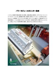
Figure 1: Isabellenhütte and <strong>Semikron</strong> act as ma<strong>in</strong> s<strong>up</strong>pliers for Siemens Drive Technologies<br />
as an ASIC for each phase.<br />
At <strong>the</strong> time, <strong>the</strong> ma<strong>in</strong> development goals<br />
and demands on <strong>the</strong> new solution were as<br />
follows:<br />
• Cutt<strong>in</strong>g costs <strong>in</strong> phase current measur<strong>in</strong>g<br />
and with a simpler mechanical construction<br />
• Reduced mount<strong>in</strong>g space and weight<br />
reduction<br />
• Account<strong>in</strong>g for power dissipation <strong>in</strong> <strong>the</strong><br />
shunt<br />
• Develop<strong>in</strong>g a suitable shunt module for<br />
high currents<br />
• Increas<strong>in</strong>g <strong>the</strong> accuracy of <strong>the</strong> entire<br />
system<br />
Cost analysis<br />
Compar<strong>in</strong>g <strong>the</strong> costs of conventional<br />
current measur<strong>in</strong>g (compensation<br />
transformer + U/f transformer) <strong>to</strong> those for<br />
shunt measur<strong>in</strong>g, it is evident that shunt<br />
Figure 2: Basic<br />
diagram of current<br />
measurement us<strong>in</strong>g a<br />
shunt<br />
Issue 7 2009 Power Electronics Europe
www.semikron.com INVERTER DESIGN 21<br />
measur<strong>in</strong>g is considerably more cost<br />
effective with <strong>the</strong> same or even <strong>in</strong>creased<br />
performance. 90% of modules demanded<br />
by <strong>the</strong> market are <strong>in</strong> <strong>the</strong> lower power<br />
ranges <strong>up</strong> <strong>to</strong> 100A, where <strong>the</strong> greatest cost<br />
sav<strong>in</strong>gs can be made.<br />
Costs can primarily be saved due <strong>to</strong> <strong>the</strong><br />
first step be<strong>in</strong>g less sophisticated<br />
(transform<strong>in</strong>g current <strong>in</strong><strong>to</strong> voltage). The<br />
downstream digitisation of <strong>the</strong><br />
measurement voltage is associated with <strong>the</strong><br />
availability of new transformers at almost<br />
<strong>the</strong> same cost. Galvanic isolation is not a<br />
significant cost fac<strong>to</strong>r thanks <strong>to</strong> <strong>the</strong> serial<br />
transfer of digitised data and is <strong>the</strong>refore no<br />
longer <strong>the</strong> significant advantage for <strong>the</strong><br />
compensation transformer that it used <strong>to</strong> be<br />
(see Figure 3).<br />
Lower construction volume<br />
In <strong>the</strong> power range <strong>up</strong> <strong>to</strong> 50A, current<br />
can still be carried via <strong>the</strong> pr<strong>in</strong>ted circuit<br />
board. This means that all measurement<br />
value logg<strong>in</strong>g from SMD shunts is <strong>in</strong><br />
comparison <strong>to</strong> transformers extremely<br />
compact and cost-effective. For higher<br />
currents, <strong>the</strong> current has <strong>to</strong> be carried via<br />
bus bars and <strong>the</strong> higher power loss<br />
respective heat generation <strong>in</strong> <strong>the</strong> shunt<br />
requires adapted construction forms.<br />
The fourth generation of IGBTs has a<br />
permissible junction temperature of 175°C.<br />
Figure 5: Paralleled<br />
circuit with <strong>up</strong> <strong>to</strong> four<br />
BVR resis<strong>to</strong>rs used<br />
for each phase<br />
Figure 3: Cost<br />
comparison between<br />
current measur<strong>in</strong>g<br />
method us<strong>in</strong>g<br />
transformers and<br />
shunts<br />
Figure 4: Loss<br />
comparison between<br />
current measur<strong>in</strong>g<br />
method us<strong>in</strong>g<br />
transformers and<br />
shunts<br />
All of its predecessors were rated at 150°C<br />
or below. The trend <strong>to</strong>wards higher<br />
temperatures – with <strong>in</strong>creased pack<strong>in</strong>g<br />
density – benefits <strong>the</strong> shunt sens<strong>in</strong>g<br />
process.<br />
Power dissipation<br />
For <strong>the</strong> current transformers, losses arise<br />
<strong>in</strong> <strong>the</strong> compensation circuit, load resis<strong>to</strong>r<br />
and <strong>in</strong> <strong>the</strong> subsequent U/f transformer. The<br />
losses <strong>in</strong> <strong>the</strong> compensation circuit are<br />
ma<strong>in</strong>ly <strong>in</strong>dependent of <strong>the</strong> measured<br />
current. However, losses <strong>in</strong> <strong>the</strong> load resis<strong>to</strong>r<br />
and <strong>the</strong> output stage of <strong>the</strong> compensation<br />
circuit are current dependent.<br />
When measur<strong>in</strong>g with shunts, <strong>the</strong> power<br />
losses <strong>in</strong> <strong>the</strong> shunt for a given maximum<br />
sens<strong>in</strong>g voltage are directly proportional <strong>to</strong><br />
<strong>the</strong> current accord<strong>in</strong>g <strong>to</strong> <strong>the</strong> follow<strong>in</strong>g<br />
equation:<br />
The maximum power dissipation is<br />
determ<strong>in</strong>ed by <strong>the</strong> voltage range of <strong>the</strong><br />
/ converter, which is at 0.2V for most<br />
exist<strong>in</strong>g current systems. At 10A, this<br />
corresponds <strong>to</strong> power dissipation of only<br />
2W, which can be handled easily by<br />
available SMD resis<strong>to</strong>rs. This is different for<br />
currents of 300A for <strong>in</strong>stance. A full voltage<br />
range of 200mV would already generate<br />
60W per phase, which is <strong>the</strong> reason that<br />
design eng<strong>in</strong>eers try <strong>to</strong> use only half of <strong>the</strong><br />
converters voltage. Never<strong>the</strong>less, <strong>the</strong> still<br />
considerable output of 30 <strong>to</strong> 100W can<br />
only be handled <strong>in</strong>sufficiently with<br />
conventional shunts, which is why <strong>the</strong><br />
power modules mentioned above were<br />
developed based on proven high power<br />
modules.<br />
Overall, it is evident that <strong>the</strong> heat<br />
generation <strong>in</strong> <strong>the</strong> shunts for low currents is<br />
no problem, whereas at <strong>the</strong> <strong>up</strong>per end of<br />
<strong>the</strong> current range it needs new solution <strong>to</strong><br />
get rid of <strong>the</strong> heat. But never<strong>the</strong>less, <strong>the</strong><br />
losses <strong>in</strong> <strong>the</strong> shunt are only less than 2%<br />
of <strong>to</strong>tal <strong>in</strong>verter losses at maximum<br />
current. Figure 4 shows a comparison<br />
between losses of <strong>the</strong> old (transformers)<br />
and <strong>the</strong> new measur<strong>in</strong>g method with<br />
shunts.<br />
<strong>Shunt</strong> module<br />
The shunt modules developed by<br />
<strong>Semikron</strong> (module hous<strong>in</strong>g) and<br />
Isabellenhütte (shunts) for high currents<br />
are optimised <strong>in</strong> terms of TCE (<strong>the</strong>rmal<br />
coefficient of expansion), offset, long-term<br />
stability and capacity, and <strong>the</strong>refore meet<br />
<strong>the</strong> above-mentioned requirements almost<br />
perfectly. They conta<strong>in</strong> a parallel circuit of<br />
<strong>up</strong> <strong>to</strong> four precision SMD resis<strong>to</strong>rs (see<br />
Figure 5) for each phase, which are<br />
mounted on<strong>to</strong> a DCB substrate for better<br />
heat dissipation. By us<strong>in</strong>g optimum<br />
resis<strong>to</strong>rs and modified geometry for <strong>the</strong><br />
DCB layout, a TK of 30ppm/K will be<br />
ma<strong>in</strong>ta<strong>in</strong>ed for all modules.<br />
The shunt modules are used by Siemens<br />
<strong>in</strong> all new SINAMICS <strong>in</strong>verters <strong>in</strong> <strong>the</strong><br />
correspond<strong>in</strong>g performance class. S<strong>in</strong>ce<br />
<strong>the</strong>ir <strong>in</strong>troduction, over 100,000 modules<br />
have been deployed <strong>in</strong> <strong>in</strong>dustrial<br />
applications with big success. Table 1 gives<br />
an overview of available <strong>Semikron</strong><br />
modules.<br />
These RoHS conform<strong>in</strong>g modules are<br />
limited <strong>to</strong> a nom<strong>in</strong>al voltage of <strong>up</strong> <strong>to</strong><br />
690VAC. However, <strong>the</strong> current load limit for<br />
this module form has been reached with<br />
<strong>the</strong> SKKR 800/0.1 model, <strong>in</strong> spite of<br />
adaptations <strong>to</strong> <strong>the</strong> plate geometry of <strong>the</strong><br />
current s<strong>up</strong>plies. The altered plate<br />
geometry helped improve <strong>the</strong> module’s<br />
robustness and reliability, and <strong>the</strong> exterior<br />
shape rema<strong>in</strong>ed <strong>the</strong> same, mak<strong>in</strong>g<br />
<strong>in</strong>tegration <strong>in</strong> <strong>the</strong> device possible with <strong>the</strong><br />
same rails.<br />
S<strong>in</strong>ce 2005, <strong>the</strong> sens<strong>in</strong>g limit has<br />
<strong>in</strong>creased from 400 <strong>to</strong> 600A. A higher<br />
powered module would require <strong>the</strong><br />
follow<strong>in</strong>g:<br />
• Adapt<strong>in</strong>g <strong>the</strong> resistance value of <strong>the</strong> shunt<br />
<strong>to</strong> higher currents<br />
• New module hous<strong>in</strong>g for higher currents<br />
• Stronger power rails<br />
• Reduc<strong>in</strong>g lead losses<br />
Power Electronics Europe Issue 7 2009
22 INVERTER DESIGN www.siemens.com/s<strong>in</strong>amics-g120<br />
Figure 6: IMC calibrated sensor module<br />
• Potential parallel circuit<strong>in</strong>g of modules<br />
• Reduc<strong>in</strong>g <strong>the</strong> voltage output of <strong>the</strong><br />
transformer.<br />
Additional advantages of <strong>the</strong>se modules<br />
<strong>in</strong>clude:<br />
• Familiar hous<strong>in</strong>g<br />
• It is easier for <strong>the</strong> construction <strong>to</strong> <strong>in</strong>tegrate<br />
<strong>the</strong> module <strong>in</strong><strong>to</strong> an exist<strong>in</strong>g concept and<br />
potentially add available materials (rails,<br />
<strong>in</strong>sula<strong>to</strong>r s<strong>up</strong>ports, etc.)<br />
• Cus<strong>to</strong>mised solutions can be produced<br />
relatively quickly.<br />
<strong>Measur<strong>in</strong>g</strong> accuracy requirements<br />
The quality of any measur<strong>in</strong>g system is<br />
determ<strong>in</strong>ed by <strong>the</strong> resolution, offset, noise,<br />
ga<strong>in</strong> and l<strong>in</strong>earity errors, as well as by<br />
temperature and long-term drift. The<br />
absolute accuracy of <strong>the</strong> actual current<br />
values has a direct impact on <strong>the</strong><br />
performance of an <strong>in</strong>verter or <strong>the</strong> drive.<br />
Us<strong>in</strong>g <strong>the</strong>se types of <strong>in</strong>verters <strong>in</strong> mach<strong>in</strong>e<br />
<strong>to</strong>ols permits mach<strong>in</strong><strong>in</strong>g of a surface with a<br />
quality better than 0.2µm due <strong>to</strong> a very low<br />
<strong>to</strong>rque ripple.<br />
The resolution is primarily determ<strong>in</strong>ed by<br />
digitisation and is less dependent on <strong>the</strong><br />
analogous path, as a result of which this<br />
issue is not discussed here any fur<strong>the</strong>r.<br />
Siemens’ target for offset errors was<br />
www.isabellenhuette.de 23<br />
optimum values for <strong>the</strong>se<br />
measurements and comfortably<br />
meet <strong>the</strong> requirements.<br />
Both methods can meet <strong>the</strong><br />
requirements for l<strong>in</strong>earity without<br />
any special measures be<strong>in</strong>g taken.<br />
However, shunt measur<strong>in</strong>g still has a<br />
lot of unused potential <strong>in</strong> this<br />
respect.<br />
New developments and outlook<br />
In spite of <strong>the</strong> advantages shunt<br />
current sens<strong>in</strong>g has <strong>to</strong> offer versus<br />
current transformers and o<strong>the</strong>r<br />
magnetic measur<strong>in</strong>g methods,<br />
<strong>the</strong>re are still limitations <strong>in</strong> <strong>the</strong><br />
power output over 600A as a<br />
result of extremely high power<br />
generation with<strong>in</strong> <strong>the</strong> shunt.<br />
Parallel connection of numerous<br />
modules may solve <strong>the</strong> heat<strong>in</strong>g<br />
problem, thanks <strong>to</strong> <strong>the</strong> l<strong>in</strong>ear<br />
dependency of power dissipation<br />
on <strong>the</strong> current output. However,<br />
this solution is not ideal because<br />
of <strong>the</strong> space requirement and cost<br />
aspects. Power dissipation of 30 <strong>to</strong><br />
100W just for <strong>the</strong> measurement<br />
cannot be justified <strong>in</strong> <strong>the</strong> longterm,<br />
particularly as <strong>the</strong> trend<br />
<strong>to</strong>wards us<strong>in</strong>g electric energy<br />
economically is becom<strong>in</strong>g<br />
cont<strong>in</strong>uously stronger.<br />
That is why fur<strong>the</strong>r considerable<br />
improvement and <strong>in</strong>novation <strong>in</strong><br />
measur<strong>in</strong>g technology are<br />
<strong>in</strong>evitable for shunt measur<strong>in</strong>g<br />
applications <strong>in</strong> o<strong>the</strong>r sec<strong>to</strong>rs, such<br />
as au<strong>to</strong>motive technology or solar<br />
technology. The <strong>in</strong>terest<strong>in</strong>g market<br />
volume and <strong>the</strong> achievable<br />
marg<strong>in</strong>s have triggered a real flow<br />
of ideas <strong>in</strong> <strong>the</strong> area of isolated /<br />
converters. In addition <strong>to</strong> galvanic<br />
isolation via op<strong>to</strong>co<strong>up</strong>lers,<br />
transformers based on magnetic or<br />
capacitive co<strong>up</strong>l<strong>in</strong>gs are now<br />
available from several<br />
manufacturers. This competition<br />
has led <strong>to</strong> a significant reduction <strong>in</strong><br />
prices and an improvement <strong>in</strong> <strong>the</strong><br />
product’s characteristics. The next<br />
aim will be <strong>to</strong> reduce <strong>the</strong> <strong>in</strong>put<br />
voltage range (200mV = >50mV =<br />
>20mV) while ma<strong>in</strong>ta<strong>in</strong><strong>in</strong>g <strong>the</strong><br />
same accuracy. This would offer<br />
<strong>the</strong> advantage that power<br />
dissipation could be reduced by <strong>up</strong><br />
<strong>to</strong> one order of magnitude, while<br />
<strong>the</strong> solutions be even more<br />
compact with lower cost. An<br />
example of a solution from<br />
Isabellenhütte: <strong>the</strong> calibrated<br />
sensor module for direct<br />
measurement of +/-300A current,<br />
voltage and temperature with a<br />
communication via an isolated<br />
digital <strong>in</strong>terface (see Figure 6).<br />
The number of semiconduc<strong>to</strong>r<br />
manufacturers for / converters will<br />
cont<strong>in</strong>ue <strong>to</strong> <strong>in</strong>crease if <strong>the</strong><br />
requirement for isolation is dropped,<br />
and costs will come down due <strong>to</strong><br />
reduced complexity of <strong>the</strong> product<br />
and <strong>in</strong>creased sales. Galvanic<br />
isolation of <strong>the</strong> digital signals via just<br />
a s<strong>in</strong>gle co<strong>up</strong>ler can be very costeffective<br />
if <strong>the</strong> clock and data are<br />
transferred <strong>to</strong>ge<strong>the</strong>r <strong>in</strong> Manchester<br />
code.<br />
It goes without say<strong>in</strong>g that <strong>the</strong><br />
requirements on <strong>the</strong> overall design<br />
will also <strong>in</strong>crease. In an effort <strong>to</strong><br />
elim<strong>in</strong>ate <strong>in</strong>terferences from <strong>the</strong><br />
strong alternat<strong>in</strong>g magnet fields, <strong>the</strong><br />
/ converter will have <strong>to</strong> be<br />
mounted right next <strong>to</strong> <strong>the</strong> shunt, or<br />
even <strong>to</strong>ge<strong>the</strong>r with <strong>the</strong> shunt, which<br />
<strong>in</strong> turn, also reduces size and cost.<br />
These types of modules with an<br />
<strong>in</strong>tegrated current sens<strong>in</strong>g (200mV<br />
converter) have already been<br />
<strong>in</strong>troduced. In this case, high power<br />
dissipation results <strong>in</strong> unnecessarily<br />
large and expensive solutions. Figure<br />
7 shows <strong>the</strong> IHC measur<strong>in</strong>g module<br />
with galvanic isolation for currents<br />
<strong>up</strong> <strong>to</strong> 2000A.<br />
It is likely that new<br />
semiconduc<strong>to</strong>r developments <strong>in</strong><br />
downstream electronics will also<br />
contribute <strong>to</strong> this technology<br />
becom<strong>in</strong>g more widely used <strong>in</strong> <strong>the</strong><br />
drive technology and solar<br />
technology sec<strong>to</strong>rs. Mo<strong>to</strong>r<br />
controllers are currently be<strong>in</strong>g<br />
prepared, which are able <strong>to</strong> directly<br />
process <strong>the</strong> data streams of all<br />
three shunts (three phases) and<br />
convert <strong>the</strong>m <strong>in</strong><strong>to</strong> a digital 12 <strong>to</strong><br />
14bit signal with a higher sampl<strong>in</strong>g<br />
rate. The measurements can be<br />
triggered at a given time after <strong>the</strong><br />
switch<strong>in</strong>g edge of <strong>the</strong> power<br />
transis<strong>to</strong>rs and a rapid over-current<br />
signal is generated.<br />
Given <strong>the</strong> lower power dissipation<br />
<strong>in</strong> <strong>the</strong> shunt, <strong>the</strong> module will become<br />
considerably smaller <strong>in</strong> <strong>the</strong> long-term<br />
(possibly even be separated for each<br />
phase) and will directly conta<strong>in</strong> <strong>the</strong><br />
/ converter and additional<br />
electronics. Fur<strong>the</strong>rmore, directly<br />
mount<strong>in</strong>g <strong>the</strong> transformer or <strong>the</strong><br />
circuit board on<strong>to</strong> <strong>the</strong> shunt is a<br />
practical way of avoid<strong>in</strong>g<br />
<strong>in</strong>terferences.<br />
Isabellenhütte has launched a<br />
number of prelim<strong>in</strong>ary developments<br />
<strong>in</strong> this direction. Pro<strong>to</strong>types for <strong>the</strong>se<br />
types of solutions are available on<br />
request.<br />
Power Electronics Europe Issue 7 2009<br />
Ready for<br />
mass production<br />
HMS<br />
Tak<strong>in</strong>g open loop technology <strong>to</strong> <strong>the</strong> next<br />
level: <strong>in</strong>troduc<strong>in</strong>g a surface mount device.<br />
Au<strong>to</strong>matic assembly<br />
Dedicated LEM ASIC <strong>in</strong>side<br />
Compatible with <strong>the</strong> microcontroller or A/D<br />
converter, reference provided outside or<br />
forced by external reference, 5 V power<br />
s<strong>up</strong>ply<br />
Improved offset and ga<strong>in</strong> drifts and<br />
enhanced l<strong>in</strong>earity over traditional open<br />
loop designs<br />
VRef IN/OUT on <strong>the</strong> same p<strong>in</strong><br />
8 mm creepage and clearance distances<br />
+ CTI: 600<br />
No <strong>in</strong>sertion losses<br />
Several current ranges from 5 <strong>to</strong> 20 A RMS<br />
SPS/IPC/<br />
Drives<br />
Hall 1.528