Development and Industrial Verification of QForm ... - Light Metal Age
Development and Industrial Verification of QForm ... - Light Metal Age
Development and Industrial Verification of QForm ... - Light Metal Age

Create successful ePaper yourself
Turn your PDF publications into a flip-book with our unique Google optimized e-Paper software.
<strong>Development</strong> <strong>and</strong> <strong>Industrial</strong> <strong>Verification</strong> <strong>of</strong><br />
<strong>QForm</strong>-Extrusion Program<br />
for Simulation <strong>of</strong> Pr<strong>of</strong>ile Extrusion<br />
By S. Stebunov <strong>and</strong> A. Lishnij, QuantorForm Ltd.; N. Biba, Micas Simulation Ltd.; <strong>and</strong><br />
S. Bellotti <strong>and</strong> P. Bevilacqua Fazzini, COMPES S.p.a.<br />
Introduction<br />
<strong>QForm</strong>-Extrusion is a special-purpose program<br />
for aluminum pr<strong>of</strong>ile extrusion simulation newly<br />
developed by QuantorForm Ltd. The s<strong>of</strong>tware<br />
includes two discreet models. The Lagrange<br />
model is for transient simulation at the first stage <strong>of</strong> the<br />
process while the Lagrange-Euler model is for simulation<br />
at a steady state stage. 1,2 At the first stage, the finite element<br />
mesh follows the material flow <strong>and</strong> by these means<br />
precisely traces the progress <strong>of</strong> the die filling. In the<br />
case <strong>of</strong> hollow pr<strong>of</strong>iles, the material flow separates at the<br />
bridges that support the m<strong>and</strong>rel <strong>and</strong> then merges again<br />
in welding zones <strong>and</strong> very clearly shows the details <strong>of</strong> the<br />
material flow. The simulation <strong>of</strong> the transient stage <strong>of</strong> extrusion<br />
is by means <strong>of</strong> the Lagrange model, which operates<br />
quite quickly at the beginning but then slows down<br />
when the material reaches the die orifice where further<br />
simulation with this model becomes ineffective.<br />
The Lagrange-Euler model is based on the assumption<br />
that the tool set is already completely filled <strong>and</strong> the<br />
domain <strong>of</strong> the material flow inside <strong>of</strong> the tool does not<br />
change. Thus the finite element mesh in the inside <strong>of</strong> the<br />
tool represents space domain subject to simulation. This<br />
means that the mesh here is immovable while the material<br />
flows through it. The advantages <strong>and</strong> drawbacks <strong>of</strong> this<br />
method were analyzed in monograph, 3 where different<br />
types <strong>of</strong> the elements were used to get the solution. This<br />
approach allows the program to not remesh the domain<br />
inside <strong>of</strong> the tools, but to just calculate the velocity in the<br />
nodes within it. On the other h<strong>and</strong>, after the die orifice,<br />
the free end <strong>of</strong> the pr<strong>of</strong>ile increases its length very quickly.<br />
Due to non-uniform material flow the pr<strong>of</strong>ile that leaves<br />
the die orifice may bend, twist, or buckle. The simulation<br />
goal is to predict this undesirable shape deterioration <strong>and</strong><br />
to find ways to minimize it. To simulate this stage <strong>of</strong> the<br />
extrusion process both the Lagrange <strong>and</strong> the Lagrange-<br />
Euler models are coupled together in <strong>QForm</strong>. Validation<br />
<strong>of</strong> the model was performed for load prediction, material<br />
flow pattern, <strong>and</strong> temperature distribution, using special<br />
model experiments <strong>and</strong> in industrial practice. The developed<br />
approach for pr<strong>of</strong>ile extrusion simulation has shown<br />
good results at the Benchmark test in Bologna. 4<br />
Simulation <strong>of</strong> Extrusion on the Basis <strong>of</strong><br />
Lagrange-Euler Approach<br />
From a practical point <strong>of</strong> view the most important part <strong>of</strong><br />
extrusion is the quasi steady-state stage, when the product<br />
shape <strong>and</strong> properties are formed. During the quasi steadystate<br />
stage <strong>of</strong> the extrusion process some parameters (temperature<br />
<strong>and</strong> load) may vary, but this variation does not<br />
influence material flow considerably <strong>and</strong> can be ignored.<br />
Generally the source data for simulation includes:<br />
• The geometric models <strong>of</strong> the tools originally created<br />
in a CAD system, which is then converted into finite-element<br />
representation<br />
• The properties <strong>of</strong> the extruded material (flow stress<br />
<strong>and</strong> thermal properties)<br />
• The conditions on the contact surface <strong>of</strong> the extruded<br />
material with the tools (friction, heat transfer coeffi-<br />
cient, <strong>and</strong> temperature <strong>of</strong> the tools)<br />
• The process parameters (initial temperature <strong>of</strong> the<br />
billet, extrusion speed, <strong>and</strong> pulling force)<br />
<strong>QForm</strong>-Extrusion is a finite-element simulation program<br />
specially developed for modeling <strong>and</strong> optimization<br />
<strong>of</strong> pr<strong>of</strong>ile extrusion. This program is a 64-bit application<br />
that allows dealing with up to 500,000 nodes on PCs with<br />
up to 16 GB <strong>of</strong> RAM <strong>and</strong> runs simulations in parallel on<br />
up to 8 CPUs. It includes a special module, QShape, to<br />
import CAD models <strong>of</strong> extrusion tools <strong>and</strong> to generate<br />
FE mesh inside the tools <strong>and</strong> to create the simulation<br />
domain. Within QShape, Bearing Editor allows modification<br />
<strong>of</strong> bearing design, i.e., the bearing length <strong>and</strong> choke<br />
angle along the bearing evolute. The mesh generation in<br />
the program is completely automated <strong>and</strong> does not require<br />
any user’s interference. The program also includes<br />
pre- <strong>and</strong> post-processors <strong>and</strong> provides different kinds <strong>of</strong><br />
visualization results <strong>and</strong> analysis.<br />
Mesh Generation in the Domain<br />
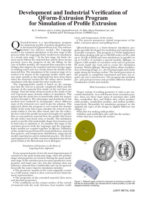
Proper setting <strong>of</strong> tooling geometry is vital to get successful<br />
simulation. As is well known from extrusion practice,<br />
there are three basic types <strong>of</strong> extrusion dies: solid<br />
dies, semihollow dies, <strong>and</strong> hollow dies, which produce<br />
solid pr<strong>of</strong>iles, semihollow pr<strong>of</strong>iles, <strong>and</strong> hollow pr<strong>of</strong>iles,<br />
respectively. Meanwhile for simulation purposes we distinguish<br />
the types <strong>of</strong> die design in slightly different way<br />
(Figure 1):<br />
• Flat dies for making solid pr<strong>of</strong>iles<br />
• Hollow <strong>and</strong> semihollow dies with flat die surface<br />
• Dies that have non-flat die surface<br />
(a)<br />
(c)<br />
Figure 1. Different types <strong>of</strong> dies for extrusion <strong>of</strong> aluminum pr<strong>of</strong>iles: (a)<br />
flat die for solid pr<strong>of</strong>iles; (b) m<strong>and</strong>rel die for hollow pr<strong>of</strong>iles; (c) die with<br />
stepped chamber <strong>of</strong> bearing.<br />
(b)<br />
LIGHT METAL AGE
Simulation <strong>of</strong> the extrusion process is performed within<br />
the so called “simulation domain.” This is the volume<br />
<strong>of</strong> the extruded material that fills the container <strong>and</strong> the<br />
inner space <strong>of</strong> the die up to the exit from the bearing<br />
l<strong>and</strong>. The domain is to be created using models <strong>of</strong> the<br />
tools. In general the domain can be created in three different<br />
ways:<br />
• For flat solid dies, it is created using two-dimensional<br />
drawings <strong>of</strong> the pr<strong>of</strong>ile, the chamber, <strong>and</strong> the container.<br />
The domain initially has the bearing <strong>of</strong> constant length<br />
that later can be modified using the Bearing Editor.<br />
• All 3D solid models <strong>of</strong> the tooling set are preliminarily<br />
merged into a single body in a CAD system as shown<br />
in Figure 2a. The domain is created by means <strong>of</strong> import<br />
<strong>of</strong> the 3D die geometry from CAD system into QShape<br />
<strong>and</strong> subsequent conversion into finite element representation.<br />
Then QShape creates the domain as shown in Figure<br />
2b-c.<br />
• The domain is created using the tools as separate<br />
parts, created in CAD, <strong>and</strong> then joined together directly<br />
in QShape program.<br />
LIGHT METAL AGE<br />
(c)<br />
Figure 2. Die set merged with the container to form a single solid body<br />
for subsequent creation <strong>of</strong> the simulation domain inside it: (a) CAD<br />
model; (b) finite element model <strong>of</strong> the tooling set; (c) simulation domain<br />
automatically generated inside <strong>of</strong> the tooling set.<br />
Currently the second option for domain generation is<br />
realized in the program while the other options are to be<br />
added soon. The most critical stage <strong>of</strong> the domain creation<br />
is automatic recognition <strong>of</strong> the bearing zone <strong>and</strong><br />
converting this part <strong>of</strong> the die design into parametric<br />
representation. Parametric representation <strong>of</strong> the bearing<br />
is necessary for its interactive modification without going<br />
back to the CAD system. After such parameterization,<br />
the geometry <strong>of</strong> the bearing is represented not by finite<br />
elements but by means <strong>of</strong> splines <strong>and</strong> can be easily modified<br />
in the program. Particularly it is possible to change<br />
the bearing length <strong>and</strong> choke angle to provide desired<br />
material flow. It is also important to have parametric representation<br />
<strong>of</strong> the bearing when dealing with the dies to<br />
produce several similar pr<strong>of</strong>iles at a time. Any modification<br />
<strong>of</strong> the bearing <strong>of</strong> a single die must be automatically<br />
repeated for all the others. The last stage is generation <strong>of</strong><br />
the finite element mesh inside the domain. As soon as the<br />
domain is created the program automatically sets proper<br />
boundary conditions over its surface <strong>and</strong> provides simulation<br />
<strong>of</strong> extrusion process to the pr<strong>of</strong>ile length specified<br />
by the user (Figure 3).<br />
Figure 3. Several steps <strong>of</strong> pr<strong>of</strong>ile extrusion simulation using the simulation<br />
domain shown in Figure 1.<br />
It is important to mention here that the sequential<br />
stages <strong>of</strong> simulation domain creation just described can<br />
be automated <strong>and</strong> an interface to other CAD/CAM programs<br />
for die design <strong>and</strong> manufacturing can be developed<br />
on request.<br />
The mesh inside the domain is built using tetrahedral<br />
elements, while the pr<strong>of</strong>ile’s exit from the die orifice is<br />
approximated by prism elements. The quality <strong>of</strong> the finite<br />
element mesh is critical to obtain accurate results. Insufficient<br />
mesh density or its over-sized gradients may cause a<br />
non-convergence problem <strong>and</strong> deteriorate the quality <strong>of</strong><br />
the simulation (Figure 4). This is especially critical if the<br />
mesh has improper density distribution at the entrance<br />
into the bearing where the most intensive deformation<br />
takes place. When the extruded pr<strong>of</strong>ile leaves the die, it<br />
is enough to have two to three elements across the pr<strong>of</strong>ile,<br />
while in the deformation zone it is necessary to have<br />
not less than ten element layers. Thus the finite element<br />
mesh is created iteratively, adapting it to solution behavior<br />
such as the velocity gradients at the entrance to the<br />
die orifice.<br />
Figure 4. The influence <strong>of</strong> the finite element mesh quality on the material<br />
flow: (a) insufficient mesh adaptation causes fluctuation <strong>of</strong> the<br />
material flow; (b) optimal adaptation provides accurate simulation.
Bearing Editor<br />
Bearing Editor is a part <strong>of</strong> the QShape program <strong>and</strong> is<br />
intended for interactive modification <strong>of</strong> bearing design.<br />
To show how it can be used, consider the simulation <strong>of</strong><br />
extrusion <strong>of</strong> hollow angular pr<strong>of</strong>iles. The first attempt <strong>of</strong><br />
the simulation has shown the same deformation <strong>of</strong> the<br />
front tip <strong>of</strong> the pr<strong>of</strong>ile as in real extrusion (Figure 5).<br />
The reason for such shape deterioration is a much lower<br />
metal velocity in the “corner” <strong>of</strong> the pr<strong>of</strong>ile that in its<br />
legs. Bearing Editor displays the evolutes <strong>of</strong> the bearing<br />
length <strong>of</strong> all contours <strong>of</strong> the pr<strong>of</strong>iles (outer <strong>and</strong> inner<br />
ones) <strong>and</strong> shows them as graphs (Figure 6). Moreover<br />
after completing the simulation, Bearing Editor displays<br />
the evolute <strong>of</strong> the velocity pr<strong>of</strong>ile on the same graph as<br />
the evolute <strong>of</strong> the bearing length, which shows how they<br />
correspond to each other (Figure 7). For this particular<br />
angular pr<strong>of</strong>ile, the initial reduction <strong>of</strong> the bearing<br />
length in the corner area <strong>of</strong> the pr<strong>of</strong>ile was not enough<br />
to equalize the velocity (Figure 8b). With further reduction,<br />
the velocity pr<strong>of</strong>ile, as well as the front end <strong>of</strong> the<br />
pr<strong>of</strong>ile, becomes uniform when it leaves the die orifice<br />
(Figure 8b).<br />
Figure 5. Comparison <strong>of</strong> real front tip (a) <strong>and</strong> its shape obtained by the<br />
simulation (b) for hollow angular pr<strong>of</strong>ile.<br />
Model <strong>Verification</strong> by Simulation <strong>of</strong> <strong>Industrial</strong> Cases<br />
<strong>Industrial</strong> verification <strong>of</strong> the program was done using a<br />
wide range <strong>of</strong> different solid <strong>and</strong> hollow pr<strong>of</strong>iles <strong>of</strong> different<br />
complexity with various extrusion ratios produced by<br />
COMPES S.p.a. More than 20 pr<strong>of</strong>iles were investigated.<br />
It is impossible to measure the velocity distribution along<br />
the pr<strong>of</strong>ile contour in real extrusion, thus one must compare<br />
the shape <strong>of</strong> the front tip <strong>of</strong> an real extruded pr<strong>of</strong>ile<br />
with the shape <strong>of</strong> the simulated prediction <strong>of</strong> the front<br />
end. There were several goals <strong>of</strong> such industrial investigation,<br />
which include:<br />
• Testing <strong>and</strong> improvement <strong>of</strong> the methods <strong>of</strong> the geometry<br />
data transfer from the industrial system <strong>of</strong> the die<br />
design into a simulation program<br />
• Estimation <strong>of</strong> the accuracy <strong>of</strong> the simulation<br />
• Use <strong>of</strong> the results <strong>of</strong> the tests for further development<br />
<strong>of</strong> numerical modeling <strong>and</strong> s<strong>of</strong>tware<br />
The results obtained in these tests were divided into<br />
three groups. The first group shows very good correspondence<br />
between simulation <strong>and</strong> real extrusion, for example,<br />
pr<strong>of</strong>iles No. 1 <strong>and</strong> No. 2 in Table I. Meanwhile, some<br />
pr<strong>of</strong>iles show a less exact but still acceptable correspondence,<br />
as in pr<strong>of</strong>ile No. 3, <strong>and</strong> yet other pr<strong>of</strong>iles show<br />
poor correspondence between simulation results <strong>and</strong> the<br />
real pr<strong>of</strong>ile, as with pr<strong>of</strong>ile No. 4.<br />
These results were analyzed <strong>and</strong> the reason for the inaccuracies<br />
was found to be insufficient mesh density in the<br />
zones <strong>of</strong> the most intensive deformation <strong>of</strong> the material at<br />
the entrance to the bearing zone. When the program was<br />
supplied with additional optimization <strong>of</strong> the mesh density<br />
the correspondence <strong>of</strong> the simulation results to real extrusion<br />
was significantly improved as seen in the second<br />
simulation for the pr<strong>of</strong>ile No. 4 (Table I). On the other<br />
h<strong>and</strong> increasing the mesh density causes extention <strong>of</strong> the<br />
overall problem size that essentially requires hundreds <strong>of</strong><br />
thous<strong>and</strong>s <strong>of</strong> nodes for industrially produced pr<strong>of</strong>iles <strong>of</strong><br />
complicated shape. To fit this dem<strong>and</strong> <strong>QForm</strong>-Extrusion<br />
Figure 6. The evolutes <strong>of</strong> outer (a) <strong>and</strong> inner (b, c) bearings <strong>of</strong> a hollow angular pr<strong>of</strong>ile displayed in Bearing Editor.<br />
LIGHT METAL AGE
Figure 7. Graph shows the evolutes <strong>of</strong> the bearing length (1), pr<strong>of</strong>ile<br />
velocity distribution (2), <strong>and</strong> average pr<strong>of</strong>ile velocity shown as a line<br />
(3).<br />
Figure 8. Two subsequent stages <strong>of</strong> bearing length optimization: (a)<br />
insufficient variation <strong>of</strong> the bearing length; (b) bearing length variation<br />
provides uniform velocity distribution.<br />
Table I. Some examples <strong>of</strong> industrial tests for different pr<strong>of</strong>iles.<br />
LIGHT METAL AGE<br />
provides highly efficient facilities for mesh generation,<br />
solving <strong>of</strong> the system <strong>of</strong> equations, <strong>and</strong> parallel computation<br />
techniques to speed up the simulation.<br />
Conclusion<br />
<strong>QForm</strong>-Extrusion is a special-purpose finite-element<br />
simulation program based on Lagrange-Euler approach<br />
for the use in industrial environment. The program has<br />
a module for data import from CAD systems that allows<br />
interactive modification <strong>of</strong> bearing design <strong>and</strong> that can<br />
also be used for bearing design optimization. The program<br />
provides automated simulation <strong>of</strong> the material flow<br />
through the die orifice <strong>and</strong> shows where the shape <strong>of</strong> the<br />
front end <strong>of</strong> the pr<strong>of</strong>ile can be compared with front tip<br />
in real extrusion. <strong>Industrial</strong> tests <strong>of</strong> the program have<br />
provided vital information on the effectiveness <strong>of</strong> this approach<br />
<strong>and</strong> supplied the data for further development<br />
<strong>of</strong> the model. After improvement <strong>of</strong> the algorithms, the<br />
program has shown very good correspondence <strong>of</strong> simulation<br />
results with real extrusion for a wide range <strong>of</strong> the<br />
pr<strong>of</strong>iles, which means it can be successfully used for die<br />
design development <strong>and</strong> extrusion technology optimization<br />
in industry.<br />
Editor’s Note: For more information, contact S. Stebunov by<br />
email at: info@qform3d.com.<br />
References<br />
1. Biba N., S. Stebunov, <strong>and</strong> A. Vlasov, “Application <strong>of</strong><br />
<strong>QForm</strong> Program for Improvement <strong>of</strong> the Die Design <strong>and</strong><br />
Pr<strong>of</strong>ile Extrusion Technology,” Proceedings <strong>of</strong> the Ninth International<br />
Aluminum Extrusion Technology Seminar & Exposition,<br />
ET Foundation, 2008.<br />
2. Stebunov S., N. Biba, <strong>and</strong> A. Lishnij, “<strong>QForm</strong>-Extrusion<br />
– The Program for Simulation <strong>and</strong> <strong>Development</strong> <strong>of</strong><br />
Pr<strong>of</strong>ile Extrusion Technology,” Proceedings <strong>of</strong> the Conference<br />
on Aluminium in Building, Moscow, Russia, 2008, pp. 82-<br />
83. 3. Danchenko V.M., A.A. Mileninn, O.M. Golovko,<br />
“Production <strong>of</strong> Pr<strong>of</strong>iles from Aluminum Alloys: Theory<br />
<strong>and</strong> Technology,” Dnepropetrovsk, Ukraine, System<br />
Technologies (In Russian), 2002.<br />
4. Donati L., L. Tomesani, M. Schikorra, A.E. Tekkaya,<br />
“Extrusion Benchmark 2007,” Proceedings <strong>of</strong> the Conference<br />
on Latest Advances in Extrusion Technology <strong>and</strong> Simulation in<br />
Europe, Bologna, Italy, 2007, pp. 89-95.