System description A EN Metal detector MDA 0103 - Erhardt-Leimer ...
System description A EN Metal detector MDA 0103 - Erhardt-Leimer ...
System description A EN Metal detector MDA 0103 - Erhardt-Leimer ...

Create successful ePaper yourself
Turn your PDF publications into a flip-book with our unique Google optimized e-Paper software.
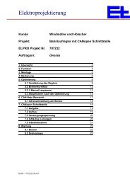
<strong>System</strong> <strong>description</strong> A<br />
<strong>Metal</strong> <strong>detector</strong><br />
<strong>MDA</strong> <strong>0103</strong><br />
1. Safety instructions 2<br />
2. Function 4<br />
3. Transport 7<br />
4. Assembly 8<br />
5. Installation 10<br />
6. Commissioning 13<br />
7. Operation 15<br />
8. Troubleshooting instructions 15<br />
9. Repair 20<br />
10. Maintenance 20<br />
11. Disassembly 20<br />
12. Spare parts 21<br />
13. Technical data 22<br />
BEA--065382-<strong>EN</strong>-06<br />
<strong>EN</strong>
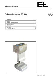
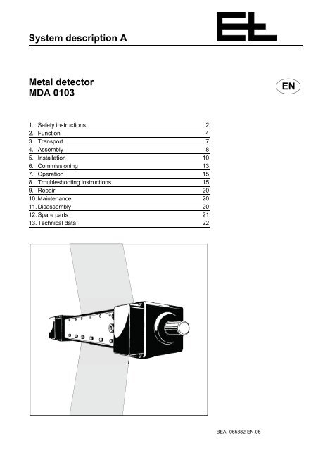
<strong>Metal</strong> <strong>detector</strong> <strong>MDA</strong> <strong>0103</strong><br />
1. Safety instructions<br />
1.1 Documentation<br />
1.2 Intended use<br />
1.3 User groups<br />
A page 2<br />
BEA--065382-<strong>EN</strong>-06<br />
Keep the documentation for the E+L system/device in a safe place and<br />
accessible for personnel at all times.<br />
The documentation is part of the scope of delivery and must be read<br />
carefully prior to starting assembly, operation or maintenance work.<br />
The documentation for an E+L system essentially comprises the higher<br />
level system <strong>description</strong> (A), the individual <strong>description</strong>s of the components<br />
(B, C, ... W), spare part lists (X) and the circuit diagrams (Z).<br />
Proceed in accordance with the instructions in the system <strong>description</strong>.<br />
All important processes are described in the system <strong>description</strong>.<br />
Where necessary, reference is made to the <strong>description</strong>s of the individual<br />
components.<br />
The metal <strong>detector</strong> is only allowed to be used for scanning textile materials.<br />
The metal <strong>detector</strong> is only allowed to be installed in the customer's machine<br />
as defined by E+L.<br />
The metal <strong>detector</strong> is not allowed to be modified.<br />
The metal <strong>detector</strong> is built to the state-of-the-art.<br />
Despite this, during use of the device<br />
– Hazards to the user's health or<br />
– Damage to property may occur.<br />
Only use the metal <strong>detector</strong><br />
– In correct working order,<br />
– With due attention to safety and hazards while observing the locally<br />
applicable, statutory and customary safety regulations as well as<br />
the regulations for the prevention of accidents.<br />
NOTICE<br />
The sensor must not be placed under mechanical load. It must not be<br />
used either as a ladder, support or depositing surface during service<br />
work.<br />
All the activities in this <strong>description</strong> are only allowed to be undertaken<br />
by the user groups listed in the following with the stated qualifications.<br />
Activities User groups Qualification<br />
Transport/assembly, commissioning,<br />
troubleshooting/repair, maintenance, disassembly<br />
Specialist personnel Technicians, industrial mechanics, fitters<br />
etc.<br />
Installation, disassembly Specialist personnel Electrical connection only by electricians
Activities User groups Qualification<br />
Operation Specialist personnel, unskilled personnel,<br />
trainees<br />
1.4 Explanation of symbols<br />
<strong>Metal</strong> <strong>detector</strong> <strong>MDA</strong> <strong>0103</strong><br />
DANGER!<br />
Signifies that death or serious injury will occur immediately if the related<br />
safety measure is not taken.<br />
WARNING!<br />
Signifies that death or serious injury may occur if the related safety<br />
measure is not taken.<br />
CAUTION!<br />
Signifies that minor injury may occur if the related safety measure is<br />
not taken.<br />
NOTICE<br />
Signifies that a malfunction or damage may occur if the related measure<br />
is not taken.<br />
Jobs to be performed.<br />
Instruction by the operating organization<br />
BEA--065382-<strong>EN</strong>-06 A page 3
<strong>Metal</strong> <strong>detector</strong> <strong>MDA</strong> <strong>0103</strong><br />
2. Function<br />
2.1 Purpose<br />
A page 4<br />
BEA--065382-<strong>EN</strong>-06<br />
The metal <strong>detector</strong> senses magnetic and non-magnetic metal particles<br />
in moving webs.<br />
Crucial for the detection of the metal particles are the type, the weight<br />
and the shape of the particles as well as the distance of the particles<br />
from the sensor.<br />
The web may be dry or damp and may be a film, woven or knitted fabric,<br />
tufting, felt, woven or tufted carpeting.<br />
The web can be moved at a speed between 0.5 and 400 meters per<br />
minute over the sensor.<br />
The detection of a particle triggers a signal that you can use in various<br />
ways:<br />
– As a continuous signal that may be manually reset. This continuous<br />
signal can be used to stop the machine<br />
– Or as a pulse signal that is reset after a specifically adjustable time.<br />
This signal can be used for example to operate a counter or a<br />
marking device.<br />
The table below indicates the weight and distance at which spherical<br />
metal particles can be detected by the system:<br />
Distance to the<br />
surface of the<br />
sensor:<br />
Steel ST 37<br />
1.0036<br />
≤1 mm ≥ 2 mg<br />
(approx. ø 0.8<br />
mm)<br />
Spherical metal particles<br />
Stainless steel<br />
A2<br />
1.4301<br />
≥ 25 mg<br />
(approx. ø 1.8<br />
mm)<br />
Aluminum<br />
3.1645<br />
≥ 8 mg<br />
(approx. ø 0.8<br />
mm)<br />
Copper,<br />
electrical grade<br />
copper<br />
2.0060<br />
≥ 10 mg<br />
(approx. ø 1.2<br />
mm)<br />
In the case of needle-shaped metal particles, sensitivity is not only dependent<br />
on the weight of the particles but also the position in which the<br />
metal needles pass the sensor (see fig. and table below).
2.2 Design<br />
Sensor MD 1003<br />
Distance to the surface<br />
of the sensor:<br />
Needle-shaped metal particles<br />
Steel 1.2206<br />
lengthwise<br />
Steel 1.2206<br />
crosswise<br />
<strong>Metal</strong> <strong>detector</strong> <strong>MDA</strong> <strong>0103</strong><br />
Steel 1.2206<br />
standing<br />
≤ 1 mm ≥ 2 mg ≥ 5 mg ≥ 2 mg<br />
≤ 5 mm ≥ 5 mg ≥ 20 mg ≥ 5 mg<br />
NOTICE<br />
Sensitivity deteriorates considerably as the distance increases between<br />
the metal particles and the sensor surface.<br />
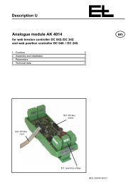
<strong>Metal</strong> particle<br />
Web<br />
Lengthwise Crosswise Standing<br />
Sensor surface<br />
6-core cable<br />
Red indicator White indicator<br />
for multiple detection<br />
Control unit SG 1030<br />
Red illuminated<br />
pushbutton<br />
The metal <strong>detector</strong> comprises a sensor MD 1003 over which the web<br />
is passed in its full width. The sensor contains a series of scanning areas<br />
arranged one behind the other, generally every 30 cm. In the middle<br />
of each scanning area is an amplifier card VK 4811 with an<br />
indicator.<br />
BEA--065382-<strong>EN</strong>-06 A page 5
<strong>Metal</strong> <strong>detector</strong> <strong>MDA</strong> <strong>0103</strong><br />
2.2.1 Accessories<br />
2.3 Operating principle<br />
A page 6<br />
BEA--065382-<strong>EN</strong>-06<br />
A shielded, 6-core cable connects the sensor to the control unit<br />
SG 1030, a red illuminated pushbutton (RESET) is built into the door<br />
of the control unit. The operating voltage of the sensor is 24 VDC.<br />
Logic card LK 3101, for the connection of external display or marking<br />
devices.<br />
An alternating electromagnetic field is established in the scanning area<br />
of the metal <strong>detector</strong>. If the web now carries a metallic foreign body<br />
over the sensor, this alternating field will be distorted and a pulse triggered.<br />
At the same time, the red indicator illuminates on the back of the sensor<br />
for the scanning area in which the metal particle was detected (see<br />
figure). The pulse signal is amplified and sent to the control device.<br />
There the red illuminated pushbutton (RESET) illuminates, either as a<br />
signal of limited duration that resets itself, or as a continuous signal.<br />
If you have connected the continuous signal to the machine contact,<br />
your production machine stops automatically and you can remove the<br />
metal particle. If you press the illuminated pushbutton on the control<br />
unit, the signal is reset and your production machine can be restarted.<br />
If three or more scanning areas trigger an alarm, a white indicator underneath<br />
the connector illuminates. This indicates that the alarm may<br />
not have not been caused by metal particles in the web.<br />
The signals from the metal <strong>detector</strong> are made available for external<br />
use at the logic card LK 3101. In this way display or marking devices<br />
can be connected that indicate the scanning area in which the metal<br />
particle was detected.<br />
2.4 Special version metal <strong>detector</strong> <strong>MDA</strong> <strong>0103</strong> master-slave<br />
A master-slave metal <strong>detector</strong> comprises:<br />
– two sensors MD 1003 with an additional socket for the connection<br />
of a coaxial cable and<br />
– two control units SG 1030.<br />
At least 1000 mm<br />
Sensor MD 1003 Master Sensor MD 1003 Slave
3. Transport<br />
3.1 Transporting and unpacking<br />
<strong>Metal</strong> <strong>detector</strong> <strong>MDA</strong> <strong>0103</strong><br />
To scan thicker non-woven materials, the two sensors are connected<br />
together to form one metal <strong>detector</strong>. One of sensors scans the top and<br />
the other the underside of the material.<br />
The mounting distance between the sensors should be at least 1 m so<br />
that the angle between the web plane and sensor plane does not exceed<br />
5°. See chapter 4.1.1 "Mounting distances".<br />
WARNING!<br />
Falling parts!<br />
Falling parts can cause injuries.<br />
Never stand under suspended loads.<br />
NOTICE<br />
The sensor must lie flat during transport. It must not suffer point loads.<br />
Risk of fracture!<br />
Only transport metal <strong>detector</strong> in the original packaging.<br />
Observe the transport instructions on the original packaging.<br />
After unpacking, check sensor and control unit for damage.<br />
Dispose of packaging material correctly.<br />
BEA--065382-<strong>EN</strong>-06 A page 7
<strong>Metal</strong> <strong>detector</strong> <strong>MDA</strong> <strong>0103</strong><br />
4. Assembly<br />
4.1 Application notes<br />
4.1.1 Mounting distances<br />
A page 8<br />
Angle < 5°<br />
BEA--065382-<strong>EN</strong>-06<br />
NOTICE<br />
The sensor must not be placed under mechanical load. It must not be<br />
used either as a ladder, support or depositing surface during service<br />
work.<br />
At least 500 mm At least 500 mm<br />
Angle < 5°<br />
The sensor can be mounted in any position and subsequently aligned<br />
with the web.<br />
The distance from the last path roller to the sensor and from the sensor<br />
to the next path roller must be at least 500 mm.<br />
Heavily magnetized, rotating steel rollers in the immediate vicinity can<br />
also interfere with the metal <strong>detector</strong>. Minimum distance approx.<br />
500 mm.<br />
In order to be able to set a high sensitivity, it must be ensured there is<br />
no interference in the electromagnetic alternating fields above the sensor.<br />
Interference is caused, for instance, by motors and transformers,<br />
by chokes, by thyristor controllers or even by fluorescent lamps and<br />
heavily loaded cables. Avoid such sources of interference building up<br />
in the area of the sensor. Minimum distance 500 mm.<br />
The web must run parallel to the sensor. Height fluctuations will corrupt<br />
the measured result. See also chapter 2.1 "Purpose".<br />
The web should be in contact with the sensor. Here it is to be ensured<br />
the angle between the web plane and the sensor plane does not exceed<br />
5°.
4.1.2 Installation position<br />
<strong>Metal</strong> <strong>detector</strong> <strong>MDA</strong> <strong>0103</strong><br />
In case of large web widths we recommend installing the metal <strong>detector</strong><br />
horizontal, with the scanning face pointing upwards.<br />
4.1.3 Mechanical center support<br />
With high web tension or a long device (from 3 m) the sensor must be<br />
supported in the center by the customer.<br />
4.1.4 Electrostatic charging<br />
4.2 Sensor MD 1003<br />
Horizontal (scanning face upwards)<br />
NOTICE<br />
The center support must be made of magnetically non-conductive material,<br />
e. g. plastic. The support point must be padded, e. g. using foam<br />
rubber.<br />
WARNING!<br />
Electric shock!<br />
Electrostatically charged webs can cause electric shock.<br />
If the web is electrostatically charged by upstream production processes,<br />
an ionizing rod that discharges the web must be installed<br />
by the customer before the metal <strong>detector</strong>.<br />
Electrostatic charges caused by the web sliding over the sensor are<br />
discharged directly by the grounding straps on the metal <strong>detector</strong>.<br />
Mount sensor. For dimensions see dimension drawing.<br />
Particular attention is to be paid to the following mounting instructions!<br />
– Relative movements (vibration) in relation to other metal parts can<br />
trigger an incorrect signal. For this reason, the sensor must not be<br />
suffer vibration.<br />
Therefore use the anti-vibration bearings supplied to mount the<br />
sensor.<br />
BEA--065382-<strong>EN</strong>-06 A page 9
<strong>Metal</strong> <strong>detector</strong> <strong>MDA</strong> <strong>0103</strong><br />
4.3 Control unit SG 1030<br />
5. Installation<br />
A page 10<br />
BEA--065382-<strong>EN</strong>-06<br />
– Excessive rotary movement of the sensor around its longitudinal<br />
axis can be avoided by fitting additional padded brackets to the end<br />
pieces.<br />
In this way you will avoid relative movement of the sensor in relation<br />
to metal parts nearby (frame structure, rollers).<br />
If the metal <strong>detector</strong> is longer than 3 meters, fit a center support.<br />
Mount control unit SG 1030 at least 1 m away from the sensor.<br />
The control unit can, like other electrical devices, interfere with the<br />
operation of the sensor.<br />
Fasten the control unit such that the illuminated pushbutton on the<br />
door can be clearly seen and is easy to operate.<br />
If necessary, install an additional external illuminated pushbutton<br />
(see also chapter Installation).<br />
WARNING!<br />
Electric shock!<br />
Live parts can cause an electric shock.<br />
Never touch live parts.<br />
Connect electrical cables as per the circuit diagram, during this<br />
task pay attention to the information on cross-section and screening.<br />
Lay signal cable separate from cables carrying interference or high<br />
currents (for example motor cables).<br />
Ensure the insulation is not damaged and the cables are properly<br />
fixed and protected.
5.1 Control unit SG 1030<br />
Transformer<br />
Line filter<br />
Line fuse<br />
4 AT for 110 to 125 V<br />
2 AT for 190 to 240 V<br />
Line connection<br />
Terminals 1 to 3<br />
Control card NK 2701<br />
<strong>Metal</strong> <strong>detector</strong> <strong>MDA</strong> <strong>0103</strong><br />
The 6-core connection cable to the sensor is 4 m long. Connect the<br />
open end to the control unit SG 1030 according to the wiring diagram.<br />
With the aid of a shielded socket, you can extend the cable to a total<br />
length of a maximum of 15 m. Use a shielded cable with a crosssection<br />
of 0.75 mm 2 .<br />
Make sure that your line voltage matches the line voltage set on the<br />
control unit SG 1030. If necessary, change the connections on the<br />
transformer.<br />
Also check the line filter connection.<br />
Connect the devices with which you want to evaluate the signal<br />
from the sensor. That is either the machine contact to stop your<br />
production machine, a counting device or a marking device<br />
BEA--065382-<strong>EN</strong>-06 A page 11
<strong>Metal</strong> <strong>detector</strong> <strong>MDA</strong> <strong>0103</strong><br />
5.2 Sensor MD 1003<br />
Connector<br />
to the control unit<br />
5.2.1 Master-slave<br />
A page 12<br />
Ground strap<br />
BEA--065382-<strong>EN</strong>-06<br />
Plug the connector on the connection cable into the socket on the<br />
sensor (see figure on left) and lock it by turning it to the right.<br />
Connect the metal grounding strap from the sensor to the earthed<br />
machine frame. Ensure the sensor is not additionally grounded.<br />
The sensor is electrically isolated from the machine frame by the<br />
anti-vibration bearings.<br />
Connect the two sensors using the co-axial cable supplied.<br />
NOTICE<br />
Make sure that the grounding straps on the sensors are connected to<br />
the same ground potential.<br />
5.3 External illuminated pushbutton "RESET"<br />
You can install an external illuminated pushbutton that, like the illuminated<br />
pushbutton on the control unit SG 1030, indicates that a metal<br />
particle has been detected and using which you can reset the continuous<br />
signal.<br />
Connect the lamp and the normally open contact according to the<br />
enclosed wiring diagram. The connection cable to the external illuminated<br />
pushbutton should be shielded and not longer than<br />
15 meters, a cable cross-section of 0.75 mm 2 is sufficient.
6. Commissioning<br />
6.1 Adjusting sensitivity<br />
WARNING!<br />
Cuts!<br />
Edges of moving webs can cause cuts.<br />
Never touch the edges of running webs.<br />
<strong>Metal</strong> <strong>detector</strong> <strong>MDA</strong> <strong>0103</strong><br />
Commissioning sequence:<br />
– Adjust sensitivity of the metal <strong>detector</strong>,<br />
– Select signal,<br />
– And, if you have set a pulse signal, the duration of this signal.<br />
You can only adjust the sensitivity of the metal <strong>detector</strong> in the range defined<br />
by the size and type of the metal particles (see table in chapter<br />
2.1 Purpose). It is therefore not possible to detect particles smaller<br />
than those given in the table. You can however reduce an excessively<br />
high sensitivity that you do not want to use.<br />
The sensitivity setting can be heavily affected by the following circumstances:<br />
– Possible electromagnetic fields in the area of the sensor,<br />
– Vibration of the sensor during operation,<br />
– <strong>Metal</strong> residue in the web due to pretreatment in metal-laden baths<br />
(for example with iron or copper oxides, titanium dioxides or zinc nitrates).<br />
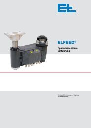
The sensitivity of the metal <strong>detector</strong> is adjusted using potentiometer R1<br />
on the sensor under the plastic cover that can be unscrewed (see figure).<br />
Potentiometer R1<br />
for the sensitivity<br />
Works setting: 8<br />
If you turn the potentiometer clockwise, the metal <strong>detector</strong> reacts<br />
more sensitively, turn it counter-clockwise to reduce the sensitivity.<br />
The upper limit is exceeded when the button on the control unit illuminates<br />
and can no longer be reset. In this case you must turn<br />
the potentiometer back until the signal can be reset again.<br />
We recommend you start by setting a value of between 8 and 9.<br />
BEA--065382-<strong>EN</strong>-06 A page 13
<strong>Metal</strong> <strong>detector</strong> <strong>MDA</strong> <strong>0103</strong><br />
6.2 Selecting signal<br />
6.3 Adjusting pulse signal<br />
A page 14<br />
BEA--065382-<strong>EN</strong>-06<br />
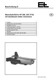
During testing you can also use button S2 in the control unit on the<br />
control card NK 2701 to reset the signal (see figure below).<br />
Potentiometer R1 for adjusting<br />
the pulse signal<br />
Light emitting diode H1 (green)<br />
Operational<br />
S1 for the selection<br />
of the signal<br />
Button S2 for resetting<br />
the signal<br />
Use switch S 1 on the control card NK 2701 to select which signal is to<br />
be used to indicate a metal particle in the web.<br />
– In position "1" (on left), a metal particle in the web will trigger a continuous<br />
signal that must be manually reset.<br />
– In position "2" (on right), a metal particle in the web generates a<br />
pulse signal of limited duration. It then resets itself automatically.<br />
The duration of the pulse signal is set using potentiometer R1 on the<br />
control card NK 2701. The potentiometer R1 has no mechanical stop.<br />
Turn 20 turns counter-clockwise to set the minimum pulse duration<br />
of half a second. Each full turn that you now make clockwise will<br />
increase the length of the pulse duration by a little more than<br />
0.1 seconds. In this way you can set a maximum pulse duration of<br />
3 seconds.
7. Operation<br />
8. Troubleshooting instructions<br />
WARNING!<br />
Cuts!<br />
Edges of moving webs can cause cuts.<br />
Never touch the edges of running webs.<br />
<strong>Metal</strong> <strong>detector</strong> <strong>MDA</strong> <strong>0103</strong><br />
NOTICE<br />
The sensor must not be placed under mechanical load. It must not be<br />
used either as a ladder, support or depositing surface during service<br />
work.<br />
The web should leave clear the outermost 20 millimeters of the scanning<br />
face, as in this area no metal particles are detected.<br />
The following applies in daily practice:<br />
The metal <strong>detector</strong> is ready for operation one minute after the operating<br />
voltage is applied.<br />
Test the function of the metal <strong>detector</strong> every day prior to starting the<br />
machine. Introduce a metal particle on a plastic rod into the scanning<br />
area and check whether a signal is triggered.<br />
WARNING!<br />
Cuts!<br />
Edges of moving webs can cause cuts.<br />
Never touch the edges of running webs.<br />
WARNING!<br />
Electric shock!<br />
Live parts can cause an electric shock.<br />
Never touch live parts.<br />
BEA--065382-<strong>EN</strong>-06 A page 15
<strong>Metal</strong> <strong>detector</strong> <strong>MDA</strong> <strong>0103</strong><br />
8.1 The metal <strong>detector</strong> no longer detects a particle on part of the scanning face<br />
Amplifier card VK 4801<br />
(up to year of manufacture 09/2009)<br />
A page 16<br />
BEA--065382-<strong>EN</strong>-06<br />
Terminal strips<br />
Fastening screw<br />
Indicator<br />
Amplifier card VK 4811<br />
(from year of manufacture 10/2009)<br />
If you find that part of the sensor no longer reacts to metal particles<br />
while the other neighboring areas signal metal particles, then the amplifier<br />
card VK 48.. is faulty in this area.<br />
First disconnect the line voltage!<br />
Unscrew the cover on the back of the sensor.<br />
Fit an amplifier card that has been checked for correct function in<br />
place of the possibly faulty card. If the area now indicates detection<br />
of metal particles (after applying the line voltage), the other card is<br />
faulty.<br />
We recommend you keep a spare amplifier card.<br />
NOTICE<br />
The amplifier cards VK 4801 and VK 4811 are not compatible.<br />
Amplifier cards VK 4801 must be sent to E+L in case of a need for<br />
spare parts.
8.2 The metal <strong>detector</strong> no longer detects any particles in the entire scanning area<br />
Operational LED<br />
Fuses<br />
8.3 The signal can no longer be reset<br />
Check whether the line voltage is applied.<br />
<strong>Metal</strong> <strong>detector</strong> <strong>MDA</strong> <strong>0103</strong><br />
Check the connections on the connection cable between sensor<br />
and control unit.<br />
Check whether, after pressing the illuminated pushbutton, the<br />
green indicator for "operational" illuminates again (see figure on<br />
left).<br />
– If it does not illuminate, check the fuses for the secondary voltage<br />
on the control card NK 2701.<br />
– If it illuminates, increase the sensitivity of the metal <strong>detector</strong> (see<br />
chapter "Commissioning").<br />
If the fault has still not been rectified, the oscillator card OK 120. or<br />
the control card NK 0501 in the sensor is faulty. These cards must<br />
be matched exactly to your system. For this reason contact E+L<br />
service.<br />
Reduce the sensitivity of the sensor (see chapter "Commissioning").<br />
Check whether the signal is triggered by external alternating electromagnetic<br />
fields, for instance from electric motors, transformers<br />
or fluorescent lamps. If this is the case, try to mount the sensor at<br />
least one meter from these sources. If necessary, select a different<br />
installation location.<br />
Check the ground strap on the sensor. It must be in contact with<br />
clean, rust-free metal on the grounded machine frame.<br />
If, in position "1", the signal output can no longer be reset using the<br />
button, or in the case of pulse operation in position "2" the output<br />
signal is a continuous signal, it is possible that one of the two control<br />
cards NK 2701/NK 0501 is faulty.<br />
Measure the operating voltage at the control board NK 2701,<br />
terminal 13 to terminal 8 and terminal 11 to terminal 12. Both voltages<br />
must be approx. +24 V. If one or both the voltages is missing,<br />
check the fuses F1 and F2 on the control card NK 2701.<br />
BEA--065382-<strong>EN</strong>-06 A page 17
<strong>Metal</strong> <strong>detector</strong> <strong>MDA</strong> <strong>0103</strong><br />
Measuring point: 8 9 7<br />
8.4 The sensitivity is inadequate<br />
A page 18<br />
BEA--065382-<strong>EN</strong>-06<br />
Measure the operating voltage on the control card NK 0501, +12 V<br />
(measuring point 8 to measuring point 9) and -12 V (measuring<br />
point 7 to measuring point 9).<br />
If all voltages are present and the signal can still not be reset, you<br />
must contact E+L service.<br />
If you have to reduce the sensitivity due to electromagnetic interference,<br />
try to mount the sensor at least one meter from the sources<br />
of the interference. If necessary, select a different installation location.<br />
Check the material and the weight of the particles and compare<br />
with the table on pages 3 and 4 as to whether these particles can<br />
be detected.<br />
Check the distance from the metal particles to the sensor is not excessively<br />
large (see table in section 2.1 Purpose).<br />
8.5 The system detects metal particles even though there are none present<br />
Check whether powering up another machine triggers the signal. If<br />
yes, connect the metal <strong>detector</strong> to a different circuit and suppress<br />
the interference on the contacts of the related machine using capacitors<br />
and resistors.<br />
Measure the line voltage. If the voltage fluctuates by more than<br />
±10 %, you must connect the system to a different circuit. Also take<br />
into account the voltage drop when the drive motor starts up.<br />
Check the electrical supply leads for faults.<br />
Check whether the sensitivity of the system is set unnecessarily<br />
high.<br />
Check the coating. Small metal particles may have become<br />
jammed in the gaps. If these particles move, they will trigger the<br />
alarm.<br />
Check whether the coating has become detached at isolated<br />
points.<br />
In the case of polyester or polyester mix fabrics, the sensor is heavily<br />
charged electrostatically. Ensure the probe is effectively grounded.<br />
If necessary, install an ionizing rod in front of the sensor to<br />
discharge the web.<br />
Vibration causes contacts to open.
The sensitivity is set too high.<br />
8.6 The red indicator illuminates on switching on the system<br />
<strong>Metal</strong> <strong>detector</strong> <strong>MDA</strong> <strong>0103</strong><br />
Check the metal <strong>detector</strong> for effects due to electromagnetic interference.<br />
The control unit SG 1030 may be mounted too close to the<br />
sensor. It must be mounted at least one meter away.<br />
Measure the line voltage. If it fluctuates by more than ±10 %, you<br />
must connect the metal <strong>detector</strong> to a different circuit. Also take into<br />
account the voltage drop when the drive motor starts.<br />
Check the coating. Damage or soiling will cause a malfunction.<br />
The sensitivity is set too high.<br />
8.7 The white indicator on the sensor illuminates<br />
If three or more scanning areas trigger an alarm, the white indicator under<br />
the connector illuminates (see figure on left). It indicates that the<br />
alarm may not have been triggered by metal particles in the web.<br />
There are several causes for multiple triggering:<br />
– A larger metal object or a machine part has been moved over the<br />
scanning face (for example a dancer roller).<br />
– The sensor has moved around its longitudinal axis. This issue is a<br />
problem if there are other machine parts near the scanning area.<br />
Signal indication for<br />
multiple detection<br />
Check if the tension on the web at the sensor is so high that the<br />
sensor is moved during operation by the web, for example by<br />
seams.<br />
If necessary reduce the wrap angle and therefore the tension and<br />
provide a central mechanical support.<br />
– Of course, by chance several metal particles in different scanning<br />
areas may cause the illumination of the white indicator.<br />
BEA--065382-<strong>EN</strong>-06 A page 19
<strong>Metal</strong> <strong>detector</strong> <strong>MDA</strong> <strong>0103</strong><br />
9. Repair<br />
10.Maintenance<br />
11.Disassembly<br />
A page 20<br />
BEA--065382-<strong>EN</strong>-06<br />
NOTICE<br />
For reasons of functional reliability, repair work on the coating and on<br />
electronic assemblies should only be undertaken at E+L.<br />
WARNING!<br />
Maintenance work is only allowed to be undertaken with the machine<br />
switched off.<br />
Switch off machine.<br />
Secure machine against switching back on.<br />
The metal <strong>detector</strong> is maintenance-free. However, the sensor should<br />
always be kept clean. Deposits increase the distance between the web<br />
and the sensor and therefore reduce the sensitivity of the system.<br />
Clean the scanning face regularly with a damp (not wet) cloth. Do<br />
not use solvents.<br />
WARNING!<br />
Disassembly is only allowed to be undertaken with the machine<br />
switched off.<br />
Switch off machine.<br />
Secure machine against switching back on.<br />
Disassemble in the reverse order of assembly as described in<br />
chapter "Assembly".<br />
During this process follow all instructions given in the chapters "Assembly"<br />
and "Installation".
12.Spare parts<br />
12.1 Oscillator card OK<br />
PC1<br />
Master<br />
Standard<br />
PC2<br />
Slave<br />
X2 X2<br />
1 2 3 1 2 3<br />
PC1 PC2<br />
OK 1202<br />
No. 325683<br />
Heat conductive paste<br />
See list of spare parts.<br />
<strong>Metal</strong> <strong>detector</strong> <strong>MDA</strong> <strong>0103</strong><br />
The oscillator card OK 1202 replaces the oscillator cards OK 1201<br />
(Standard), OK 60011 (Master) and OK 60012 (Slave).<br />
In case of replacement, the following settings are to be made on the<br />
oscillator card OK 1202:<br />
Sensor MD 1003 Standard:<br />
Fit jumper X2 to position 1-2.<br />
Sensor MD 1003 Master:<br />
Fit jumper X2 to position 1-2.<br />
Connect wire from coaxial socket to contact PC1.<br />
Sensor MD 1003 Slave:<br />
Fit jumper X2 to position 2-3.<br />
Connect wire from coaxial socket to contact PC2.<br />
NOTICE<br />
Mount oscillator board with heat conductive paste!<br />
BEA--065382-<strong>EN</strong>-06 A page 21
13.Technical data<br />
<strong>Erhardt</strong> + <strong>Leimer</strong> GmbH<br />
D-86136 Augsburg<br />
GERMANY<br />
Phone +49 (0)821 2435-0<br />
Internet http://www.erhardt-leimer.com<br />
E-Mail info@erhardt-leimer.com<br />
Nominal width NB 300 to 6000 mm<br />
(increments of 300 mm)<br />
Web type Woven and knitted, non-woven<br />
fabrics, felt, carpeting<br />
Web state Dry, moist (drained)<br />
Web speed 0.5 to 400 m/min<br />
Ambient temperature 0 to 40 °C<br />
Protection class<br />
Sensor MD 1003<br />
Control unit SG 1030<br />
IP 50<br />
IP 54<br />
Supply voltage 220/190/240 V switchable<br />
or<br />
110/125 V switchable, 50/60 Hz<br />
Control voltage 24 V DC<br />
Power consumption Approx. 160 VA<br />
Output changeover contact<br />
Switching capacity<br />
Switching voltage<br />
Switching current<br />
Subject to technical change without notice<br />
Max. 100 VA / 30 W<br />
Max. 250 v AC / 250 V DC<br />
Max. 5 A AC / 1 A DC, Ohmic<br />
load<br />
Output signal Continuous signal with reset button<br />
or pulse signal (adjustable<br />
0.5 to 3 s)<br />
Connection cable 6-core, shielded, 4 m long<br />
Dimensions W x H x D<br />
Sensor MD 1003<br />
Control unit SG 1030<br />
See dimension drawing<br />
234 x 334 x 160 mm