guide_c07-690079
guide_c07-690079
guide_c07-690079

You also want an ePaper? Increase the reach of your titles
YUMPU automatically turns print PDFs into web optimized ePapers that Google loves.
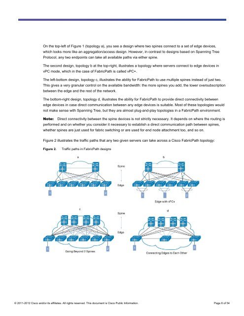
On the top-left of Figure 1 (topology a), you see a design where two spines connect to a set of edge devices,<br />
which looks more like an aggregation/access design. However, in contrast to designs based on Spanning Tree<br />
Protocol, any two endpoints can take all available paths via either spine.<br />
The second design, topology b at the top-right, illustrates a topology where servers connect to edge devices in<br />
vPC mode, which in the case of FabricPath is called vPC+.<br />
The left-bottom design, topology c, illustrates the ability for FabricPath to use multiple spines instead of just two.<br />
This gives a very granular control on the available bandwidth: the more spines you add, the lower oversubscription<br />
between the edge and the rest of the network.<br />
The bottom-right design, topology d, illustrates the ability for FabricPath to provide direct connectivity between<br />
edge devices in case direct communication between any edge devices is suitable. Most of these topologies would<br />
not make sense with Spanning Tree, but they are almost plug-and-play topologies in a FabricPath environment.<br />
Note: Direct connectivity between the spine devices is not strictly necessary. It depends on where the routing is<br />
performed and on whether you consider it necessary to establish a direct communication path between spines,<br />
whether spines are just used for fabric switching or are used for end node attachment too, and so on.<br />
Figure 2 illustrates the traffic paths that any two given servers can take across a Cisco FabricPath topology:<br />
Figure 2. Traffic paths in FabricPath designs<br />
© 2011-2012 Cisco and/or its affiliates. All rights reserved. This document is Cisco Public Information. Page 6 of 54