Technical Bulletin - Colmac Coil Manufacturing, Inc.
Technical Bulletin - Colmac Coil Manufacturing, Inc.
Technical Bulletin - Colmac Coil Manufacturing, Inc.

You also want an ePaper? Increase the reach of your titles
YUMPU automatically turns print PDFs into web optimized ePapers that Google loves.
<strong>Technical</strong> <strong>Bulletin</strong><br />
By Randy J. Carstens, P.E., Heat Transfer Products Manager, <strong>Colmac</strong> <strong>Coil</strong> <strong>Manufacturing</strong>, <strong>Inc</strong>.<br />
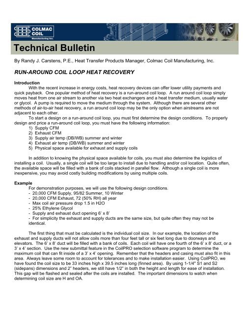
RUN-AROUND COIL LOOP HEAT RECOVERY<br />
Introduction<br />
With the recent increase in energy costs, heat recovery devices can offer lower utility payments and<br />
quick payback. One popular method of heat recovery is a run-around coil loop. A run around coil loop simply<br />
moves heat from one air stream to another via two heat exchangers and a heat transfer medium, usually water<br />
or glycol. A pump is required to move the medium through the system. Although there are several other<br />
methods of air-to-air heat recovery, a run around coil loop may be the only option when airstreams are not<br />
adjacent to each other.<br />
To start a design on a run-around coil loop, you must first determine the design conditions. To properly<br />
design and price a run-around coil loop, you must have the following information:<br />
1) Supply CFM<br />
2) Exhaust CFM<br />
3) Supply air temp (DB/WB) summer and winter<br />
4) Exhaust air temp (DB/WB) summer and winter<br />
5) Physical space available for exhaust and supply coils<br />
In addition to knowing the physical space available for coils, you must also determine the logistics of<br />
installing a coil. Usually, a single coil will be too large to install due to handling and/or coil location. Quite often,<br />
the available space will be filled with a bank of coils stacked in parallel flow. Although a single coil is more<br />
inexpensive, you may avoid costly building modifications by using multiple coils.<br />
Example<br />
For demonstration purposes, we will use the following design conditions.<br />
- 20,000 CFM Supply, 95/82 Summer, 10 Winter<br />
- 20,000 CFM Exhaust, 72 (50% RH) all year<br />
- Max coil air pressure drop 1.5 in H2O<br />
- 25% Ethylene Glycol<br />
- Supply and exhaust duct opening 6’ x 8’<br />
- For simplicity the exhaust and supply ducts are the same size, but quite often they may not be<br />
identical.<br />
The first thing that must be calculated is the individual coil size. In our example, the location of the<br />
exhaust and supply ducts will not allow coils more than four feet tall or six feet long due to doorways and<br />
elevators. The 6’ x 8’ duct will be filled with a bank of coils. Each coil will have one fourth of the 6’ x 8’ duct, or a<br />
3’ x 4’ section. Use the new submittal feature in the <strong>Coil</strong>PRO selection software program to determine the<br />
maximum coil that can fit inside of a 3’ x 4’ opening. Remember that the headers and casing must also fit in this<br />
area. Always leave some room to account for tolerances and to make installation easier. Using <strong>Coil</strong>PRO, we<br />
have found the coil size to be 33 inches high x 39.5 inches long (finned area). By using 1-1/4" S1 and S2<br />
(sidepans) dimensions and 2” headers, we still have 1/2” in both the height and length for ease of installation.<br />
This gap will be flashed and sealed after the coils are installed. The important dimensions to watch when<br />
determining coil size are H and OA.
Now that we have our individual coil size, we can go to <strong>Coil</strong>PRO and design our coils. Open <strong>Coil</strong>PRO<br />
and bring up one hot water/sensible cooling module and one chilled water module. In both sizing screens, enter<br />
the coil data. Rows and FPI will be optimized later to give us the best performance. Before we optimize the<br />
rows and FPI, we need to determine approximate flow rate.<br />
To do this, we must determine the BTUH’s available in the exhaust air. How much energy must be taken<br />
out of 20,000 CFM to cool it from 72°F 50% RH down to 10°F? This can be determined a couple of different<br />
ways. You can use <strong>Coil</strong>PRO to give you this number. Go to the Chilled Water Sizing module and create a coil<br />
that will cool 20000 CFM from 72°F (50% RH) down to 10°F. This gives us 2016000 BTUH available. You may<br />
also obtain this number by taking the enthalpy of the two points on the psychrometric chart and subtracting.<br />
This gives us 2010950 BTUH available.<br />
Now that we have the available BTUH, we must decide how much of that available energy we want to<br />
recover. A practical value is between 30 and 60%. We will use 40% for our example. We must also know the<br />
temperature difference (TD) of the water as it passes through the coils. Typical TD’s are 5 to 15 degrees. The<br />
lower the TD, the higher the required flow rate. The higher flow rate will increase pump horsepower and line<br />
sizes, but will generally yield higher heat recovery. We will choose a 10° TD for our example. The following<br />
formula gives us estimated GPM:<br />
BTUH = CONS x GPM x TD, (.40 x 2016000 = 450 (450 for glycol, 500 for water) x GPM x 10). GPM = 179.<br />
Now that we have determined the flow rate, we can go to <strong>Coil</strong>PRO and design our coils. Input all of the<br />
design information and everything we have calculated up to this point. Since we are using a bank of four coils,<br />
each coil will see 5000 CFM and 45 GPM. We have been given the supply and exhaust air temps and we have<br />
calculated the maximum coil face (33 x 39.5).<br />
There are four main variables that will affect coil performance:<br />
1) Rows<br />
2) Fins per inch (FPI)<br />
3) Circuiting<br />
4) Waffle or flat fins<br />
Usually, waffle fins will return the most cost effective coil. The goal of our design is to balance the<br />
BTUH’s that both coils transfer. To do this, we must switch between the chilled water and hot water coil<br />
modules and iterate until the entering water temp from one matches the leaving water temp of the other.<br />
Remember that the chilled water coil will be the air that is being cooled, the hot water coil is the air<br />
stream being heated. In other words, you will use the chilled water module to model the supply air in the<br />
summer and the exhaust air in the winter.<br />
To start our design, we need an initial guess for our water temperatures. We have calculated our flow<br />
rate to give us a 10° TD and we know the glycol will be running somewhere between 10 and 72 degrees (winter<br />
operation). From this we can guess that the chilled water (exhaust coils in this case) entering glycol temp will be<br />
35°F and the hot water coil will be 45°F.<br />
Now we can go to <strong>Coil</strong>PRO with these initial guesses and adjust them until the coils balance. Keep in<br />
mind that you will have to play with the number of rows, fins per inch and circuiting until you get a good design<br />
(one that gives the performance without an unacceptable air pressure drop). Adjust your circuiting (especially<br />
important with glycol) to give tube velocities above 3 FPS. After balancing the rows, FPI, circuiting and glycol<br />
temperature, we have chosen an 8 row, 8 FPI coil, 11 feed, 16 pass coil that provides 190000 BTUH of heat<br />
recovery.
In total, the bank of coils is recovering 760 MBH, or 37% of the heat available. The air pressure drop<br />
through the coils is 1 ¼” inH2O. Usually, this is a higher number than the system fans can handle, but for this<br />
example it is acceptable. You may have to accept a lower recovery efficiency to get a coil air pressure drop that<br />
the system can support.<br />
Keep in mind that less rows and more FPI make a less expensive coil, but the penalty is air pressure<br />
drop. Remember that the system fans must overcome the air pressure drop of the new run around coil system<br />
so we need to minimize the air pressure drop as much as possible.<br />
Final System Design<br />
(4) BWL-33x39.5-8R-8F per duct<br />
EXHAUST SUPPLY<br />
WINTER SUMMER WINTER SUMMER<br />
EWT 40 85 49 82<br />
LWT 49 82 40 85<br />
WPD 16.2 14.1 15.9 14.1<br />
EAT 72/50% 72/50% 10 95/82<br />
LAT 46/45.5 84 45 83.5/79.3<br />
APD 1.25 .75 0.75 .75<br />
BTUH 760000 256000 760000 256000<br />
The system will require a pump estimate Hp= (gpm x total system pressure loss in feet of water x specific<br />
gravity of fluid if other than water)/3960, a surge tank, and misc. valves and fittings to complete the installation.<br />
Heat recovery systems typically utilize 4 to 8 row coils. To keep air pressure drop low, always maximize<br />
the face area of your coil. Typical face velocities should run between 300-600 FPM. Velocity over 600 FPM will<br />
result in substantial water carry-over from the coil to the ductwork.<br />
Since the system will rarely operate at design conditions, you may have to run several different design<br />
conditions to estimate yearly energy recovery.<br />
For more information, please contact <strong>Colmac</strong> <strong>Coil</strong> <strong>Manufacturing</strong>, <strong>Inc</strong>.<br />
Email mail@colmaccoil.com; Phone (800) 845-6778 or (509) 684-2595<br />
P.O. Box 571, Colville, WA. 99114-0571; Website www.colmaccoil.com<br />
Copyright© 2009 <strong>Colmac</strong> <strong>Coil</strong> <strong>Manufacturing</strong>, <strong>Inc</strong>.