

Rexroth IndraDyn L Synchronous Linear Motors - Elogia
Rexroth IndraDyn L Synchronous Linear Motors - Elogia
Rexroth IndraDyn L Synchronous Linear Motors - Elogia

Create successful ePaper yourself
Turn your PDF publications into a flip-book with our unique Google optimized e-Paper software.
Industrial<br />
Hydraulics<br />
Electric Drives<br />
and Controls<br />
exroth IndraControl VCP 20<br />
<strong>Linear</strong> Motion and<br />
Assembly Technologies Pneumatics<br />
<strong>Rexroth</strong> <strong>IndraDyn</strong> L<br />
<strong>Synchronous</strong> <strong>Linear</strong> <strong>Motors</strong><br />
Project Planning Manual<br />
Service<br />
Automation<br />
Mobile<br />
Hydraulics<br />
R911293635<br />
Edition 01
About this documentation <strong>Rexroth</strong> <strong>IndraDyn</strong> L<br />
Title<br />
Type of Documentation<br />
Document Typecode<br />
Internal File Reference<br />
Purpose of Documentation<br />
Record of Revisions<br />
Copyright<br />
Validity<br />
Published by<br />
Note<br />
<strong>Rexroth</strong> <strong>IndraDyn</strong> L<br />
<strong>Synchronous</strong> <strong>Linear</strong> <strong>Motors</strong><br />
Project Planning Manual<br />
DOK-MOTOR*-MLF********-PR01-EN-P<br />
• R91129363501_Book.doc<br />
• Document Number, 120-1500-B319-01-EN<br />
This documentation ....<br />
• explains product features and applications, technical data as well as<br />
conditions and limits for operation<br />
• provides guidlines for product selection, application, handling and<br />
operation.<br />
Description Release<br />
Date<br />
Notes<br />
DOK-MOTOR*-MLF********-PR01-EN-P June04 1 st edition<br />
© Bosch <strong>Rexroth</strong> AG, 2004<br />
Copying this document, giving it to others and the use or communication<br />
of the contents thereof without express authority, are forbidden.<br />
Offenders are liable for the payment of damages. All rights are reserved<br />
in the event of the grand of a patent or the registration of a utility model<br />
or design (DIN 34-1).<br />
The specified data is for product description purposes only and may not<br />
be deemed to be guaranteed unless expressly confirmed in the contract.<br />
All rights are reserved with respect to the content of this documentation<br />
and the availability of the product.<br />
Bosch <strong>Rexroth</strong> AG<br />
Bgm.-Dr.-Nebel-Str. 2 • D-97816 Lohr a. Main<br />
Tel +49 (0)93 52 / 40-0 • Tx 68 94 21 • Fax +49 (0)93 52 / 40-48 85<br />
http://www.boschrexroth.com/<br />
Dept. BRC/EDM1 (FS)<br />
This document has been printed on chlorine-free bleached paper.<br />
DOK-MOTOR*-MLF********-PR01-EN-P
<strong>Rexroth</strong> <strong>IndraDyn</strong> L Contents I<br />
Contents<br />
1 Introduction to the Product 1<br />
1.1 Application range of linear direct drives .......................................................................................1<br />
1.2 About this Documentation............................................................................................................3<br />
Additional components ...........................................................................................................4<br />
Feedback ...............................................................................................................................4<br />
Standards...............................................................................................................................4<br />
2 Important directions for use 2-1<br />
2.1 Appropriate use........................................................................................................................2-1<br />
Introduction .........................................................................................................................2-1<br />
Areas of use and application................................................................................................2-2<br />
2.2 Inappropriate use .....................................................................................................................2-2<br />
3 Safety Instructions for Electric Drives and Controls 3-1<br />
3.1 Introduction ..............................................................................................................................3-1<br />
3.2 Explanations ............................................................................................................................3-1<br />
3.3 Hazards by Improper Use.........................................................................................................3-2<br />
3.4 General Information..................................................................................................................3-3<br />
3.5 Protection Against Contact with Electrical Parts........................................................................3-4<br />
3.6 Protection Against Electric Shock by Protective Low Voltage (PELV)........................................3-6<br />
3.7 Protection Against Dangerous Movements ...............................................................................3-7<br />
3.8 Protection Against Magnetic and Electromagnetic Fields During Operation and<br />
Mounting..................................................................................................................................3-9<br />
3.9 Protection Against Contact with Hot Parts...............................................................................3-10<br />
3.10 Protection During Handling and Mounting...............................................................................3-10<br />
3.11 Battery Safety.........................................................................................................................3-10<br />
3.12 Protection Against Pressurized Systems.................................................................................3-11<br />
4 Technical Data <strong>IndraDyn</strong> L 1<br />
4.1 Explanation to technical data.......................................................................................................1<br />
4.2 Technical data – size 040............................................................................................................4<br />
4.3 Technical data – size 070............................................................................................................5<br />
4.4 Technical data – size 100............................................................................................................7<br />
4.5 Technical data – size 140............................................................................................................8<br />
4.6 Technical data – size 200............................................................................................................9<br />
4.7 Technical data – size 300..........................................................................................................10<br />
5 Dimensions, installation dimension and - tolerances 5-1<br />
5.1 Installation tolerances...............................................................................................................5-1<br />
DOK-MOTOR*-MLF********-PR01-EN-P
II Contents <strong>Rexroth</strong> <strong>IndraDyn</strong> L<br />
5.2 Mounting Sizes.........................................................................................................................5-3<br />
Size 040, primary in standard encapsulation........................................................................5-3<br />
Size 040, primary in thermal encapsulation..........................................................................5-4<br />
Size 040, secondary............................................................................................................5-5<br />
Size 070, primary in standard encapsulation........................................................................5-6<br />
Size 070, primary in thermal encapsulation..........................................................................5-7<br />
Size 070, secondary............................................................................................................5-8<br />
Size 100, primary in standard encapsulation........................................................................5-9<br />
Size 100, primary in thermal encapsulation........................................................................5-10<br />
Size 100, secondary..........................................................................................................5-11<br />
Size 140, primary in standard encapsulation......................................................................5-12<br />
Size 140, primary in thermal encapsulation........................................................................5-13<br />
Size 140, secondary..........................................................................................................5-14<br />
Size 200, primary in standard encapsulation......................................................................5-15<br />
Size 200, primary in thermal encapsulation........................................................................5-16<br />
Size 200, secondary..........................................................................................................5-17<br />
Size 300, primary in standard encapsulation......................................................................5-18<br />
Size 300, primary in thermal encapsulation........................................................................5-19<br />
Size 300, secondary..........................................................................................................5-20<br />
6 Type codes for the <strong>IndraDyn</strong> L 1<br />
6.1 Description..................................................................................................................................1<br />
Type code of the Primary – The MLP......................................................................................2<br />
Type code of the Secondary – The MLS .................................................................................4<br />
6.2 Type code for <strong>IndraDyn</strong> L 040 .....................................................................................................6<br />
6.3 Type code <strong>IndraDyn</strong> L 070 ..........................................................................................................8<br />
6.4 Type code for <strong>IndraDyn</strong> L 100 ...................................................................................................10<br />
6.5 Type code for <strong>IndraDyn</strong> L 140 ...................................................................................................12<br />
6.6 Type code for <strong>IndraDyn</strong> L 200 ...................................................................................................14<br />
6.7 Type code for <strong>IndraDyn</strong> L 300 ...................................................................................................16<br />
7 Accessories and Options 7-1<br />
7.1 Hall sensor box ........................................................................................................................7-1<br />
Schematic assembly............................................................................................................7-2<br />
8 Electrical connection 8-1<br />
8.1 Power connection.....................................................................................................................8-1<br />
Connection cable on the primary .........................................................................................8-1<br />
Power Cable Connection .....................................................................................................8-3<br />
Connection of IndraDrive Drive Controller ............................................................................8-6<br />
Connection of DIAX04 and EcoDrive Drive-Controllers ........................................................8-8<br />
8.2 Connection of linear feedback devices....................................................................................8-10<br />
9 Application and Construction Instructions 9-1<br />
9.1 Functional principle ..................................................................................................................9-1<br />
9.2 Motor Design............................................................................................................................9-2<br />
DOK-MOTOR*-MLF********-PR01-EN-P
<strong>Rexroth</strong> <strong>IndraDyn</strong> L Inhaltsverzeichnis III<br />
Primary in standard encapsulation.......................................................................................9-3<br />
Primary in thermal encapsulation.........................................................................................9-4<br />
Design secondary part.........................................................................................................9-5<br />
Motor Sizes .........................................................................................................................9-6<br />
9.3 Requirements on the Machine Design ......................................................................................9-7<br />
Mass reduction....................................................................................................................9-7<br />
Mechanical rigidity...............................................................................................................9-7<br />
9.4 Arrangement of Motor Components..........................................................................................9-9<br />
Single arrangement .............................................................................................................9-9<br />
Several motors per axis.....................................................................................................9-10<br />
Vertical axes......................................................................................................................9-17<br />
9.5 Feed and Attractive Forces.....................................................................................................9-18<br />
Attractive forces between the primary and the secondary...................................................9-18<br />
Air-gap-related attractive forces between the primary and the secondary ...........................9-19<br />
Air-gap-related attractive forces vs. power supply ..............................................................9-19<br />
Air-gap-related feed force ..................................................................................................9-20<br />
Reduced overlapping between the primary and the secondary...........................................9-20<br />
9.6 Motor cooling .........................................................................................................................9-22<br />
Thermal behavior of linear motors......................................................................................9-22<br />
Cooling concept of <strong>IndraDyn</strong> L synchronous linear motors .................................................9-24<br />
Coolant..............................................................................................................................9-26<br />
Sizing the cooling circuit ....................................................................................................9-29<br />
Liquid cooling system ........................................................................................................9-33<br />
9.7 Motor temperature Monitoring Circuit......................................................................................9-38<br />
9.8 Setup Elevation and Ambient Conditions ................................................................................9-41<br />
9.9 Protection Class .....................................................................................................................9-42<br />
9.10 Compatibility ..........................................................................................................................9-42<br />
9.11 Magnetic Fields ......................................................................................................................9-43<br />
9.12 Vibration and Shock ...............................................................................................................9-44<br />
9.13 Enclosure surface ..................................................................................................................9-45<br />
9.14 Noise emission.......................................................................................................................9-45<br />
9.15 Length Measuring System ......................................................................................................9-46<br />
Selection criteria for linear scales.......................................................................................9-46<br />
Mounting <strong>Linear</strong> scales......................................................................................................9-52<br />
9.16 <strong>Linear</strong> Guides.........................................................................................................................9-53<br />
9.17 Braking Systems and Holding Devices ...................................................................................9-53<br />
9.18 End Position shock absorber ..................................................................................................9-54<br />
9.19 Axis Cover System.................................................................................................................9-55<br />
9.20 Wipers ...................................................................................................................................9-56<br />
9.21 Drive and Control of <strong>IndraDyn</strong> L motors..................................................................................9-57<br />
Drive controller and power supply modules........................................................................9-57<br />
Control systems.................................................................................................................9-57<br />
9.22 Shutdown upon EMERGENCY STOP and in the Event of a Malfunction.................................9-58<br />
Shutdown by the drive .......................................................................................................9-58<br />
Shutdown by a master control............................................................................................9-59<br />
Shutdown via mechanical braking device...........................................................................9-59<br />
DOK-MOTOR*-MLF********-PR01-EN-P
IV Inhaltsverzeichnis <strong>Rexroth</strong> <strong>IndraDyn</strong> L<br />
Response to a mains failure ..............................................................................................9-60<br />
Short-circuit of DC bus ......................................................................................................9-60<br />
9.23 Maximum Acceleration Changes (Jerk Limitation)...................................................................9-61<br />
9.24 Position and Velocity Resolution.............................................................................................9-63<br />
9.25 Load Rigidity ..........................................................................................................................9-64<br />
Static load rigidity ..............................................................................................................9-65<br />
Dynamic load rigidity .........................................................................................................9-65<br />
10 Motor-Controller-Combinations 10-1<br />
10.1 General explanation ...............................................................................................................10-1<br />
Explanation of the variables...............................................................................................10-2<br />
10.2 Motor/Controller Combinations; one primary per drive ............................................................10-3<br />
Controlled DC Bus Voltage, mains supply voltage - 3 x 480 VAC.......................................10-3<br />
10.3 Motor/Controller Combinations; parallel primaries on single drive controllers...........................10-6<br />
Controlled DC Bus Voltage, mains supply voltage - 3 x 480 VAC.......................................10-6<br />
11 Motor Sizing 1<br />
11.1 General Procedure......................................................................................................................1<br />
11.2 Basic formulae ............................................................................................................................2<br />
General equations of motion...................................................................................................2<br />
Feed forces ............................................................................................................................3<br />
Average velocity.....................................................................................................................5<br />
Trapezoidal velocity................................................................................................................6<br />
Triangular velocity ................................................................................................................10<br />
Sinusoidal velocity................................................................................................................11<br />
11.3 Duty cycle and Feed Force........................................................................................................13<br />
Determining the duty cycle....................................................................................................13<br />
11.4 Determining the Drive Power.....................................................................................................15<br />
Continuous Output ...............................................................................................................15<br />
Maximum Output..................................................................................................................16<br />
Cooling capacity...................................................................................................................17<br />
Regeneration energy ............................................................................................................17<br />
11.5 Efficiency ..................................................................................................................................18<br />
11.6 Sizing Examples........................................................................................................................19<br />
Handling axis........................................................................................................................19<br />
Machine tool feed axis; sizing via duty cycle .........................................................................28<br />
12 Handling, transportion and storage of the units 12-1<br />
12.1 Identification of the motor components ...................................................................................12-1<br />
Primary .............................................................................................................................12-1<br />
Secondary.........................................................................................................................12-1<br />
12.2 Delivery status and Packaging................................................................................................12-2<br />
12.3 Transportation and Storage ....................................................................................................12-3<br />
Specifics for transporting secondaries of synchronous linear motors..................................12-4<br />
12.4 Checking the motor components ............................................................................................12-5<br />
Factory checks ..................................................................................................................12-5<br />
DOK-MOTOR*-MLF********-PR01-EN-P
<strong>Rexroth</strong> <strong>IndraDyn</strong> L Inhaltsverzeichnis V<br />
Customer’s receiving inspection ........................................................................................12-5<br />
13 Mounting Instructions 13-1<br />
13.1 Basic precondition..................................................................................................................13-1<br />
13.2 General procedure at mounting of the motor components.......................................................13-1<br />
Installation at spanned secondary parts over the entire traverse path.................................13-1<br />
Installation at whole secondary over the entire traverse path .............................................13-3<br />
13.3 Installation of the secondary segments ...................................................................................13-5<br />
13.4 Installation of the primary........................................................................................................13-7<br />
13.5 Connection liquid cooling........................................................................................................13-7<br />
13.6 Screw locking.........................................................................................................................13-8<br />
14 Startup, Operation and Maintenance 14-1<br />
14.1 General information for startup of <strong>IndraDyn</strong> L motors..............................................................14-1<br />
14.2 General precondition ..............................................................................................................14-2<br />
Adherence of all electrically and mechanically components ...............................................14-2<br />
Implements .......................................................................................................................14-3<br />
14.3 General start-up procedure.....................................................................................................14-4<br />
14.4 Parametrization......................................................................................................................14-5<br />
Entering motor parameters ................................................................................................14-5<br />
Input of linear scale parameters.........................................................................................14-6<br />
Input of drive limitations and application-related parameters ..............................................14-6<br />
14.5 Determining the Polarity of the linear scale .............................................................................14-7<br />
14.6 Commutation adjustment........................................................................................................14-9<br />
Method 1: Measuring the reference between the primary and the secondary ...................14-11<br />
Method 2: Current flow method manually activated..........................................................14-14<br />
Method 3: Current flow method automatically activated....................................................14-15<br />
14.7 Setting and Optimizing the Control Loop...............................................................................14-16<br />
General sequence ...........................................................................................................14-16<br />
Parameter value assignments and optimization of Gantry axes........................................14-18<br />
Estimating the moved mass using a velocity ramp ...........................................................14-19<br />
14.8 Maintenance and check of Motor components ......................................................................14-21<br />
Check of Motor and Auxiliary Components ......................................................................14-21<br />
Electrical check of motor components..............................................................................14-21<br />
15 Service & Support 15-1<br />
15.1 Helpdesk................................................................................................................................15-1<br />
15.2 Service-Hotline.......................................................................................................................15-1<br />
15.3 Internet...................................................................................................................................15-1<br />
15.4 Vor der Kontaktaufnahme... - Before contacting us... ..............................................................15-1<br />
15.5 Kundenbetreuungsstellen - Sales & Service Facilities.............................................................15-2<br />
16 Appendix 16-1<br />
16.1 Recommended suppliers of additional components ................................................................16-1<br />
Length Measuring System .................................................................................................16-1<br />
<strong>Linear</strong> Guide......................................................................................................................16-1<br />
DOK-MOTOR*-MLF********-PR01-EN-P
VI Inhaltsverzeichnis <strong>Rexroth</strong> <strong>IndraDyn</strong> L<br />
Energy Chains...................................................................................................................16-1<br />
Heat-exchanger Unit..........................................................................................................16-2<br />
Coolant Additives ..............................................................................................................16-2<br />
Coolant Tubes...................................................................................................................16-2<br />
Axis Cover System ............................................................................................................16-2<br />
End Position Shock Absorbers...........................................................................................16-3<br />
Clamping Elements for <strong>Linear</strong> Guideways..........................................................................16-3<br />
External Mechanical Brakes ..............................................................................................16-4<br />
Weight Compensation Systems .........................................................................................16-4<br />
Wipers...............................................................................................................................16-4<br />
16.2 Enquiry form for <strong>Linear</strong> Drives ................................................................................................16-5<br />
17 Index 17-1<br />
DOK-MOTOR*-MLF********-PR01-EN-P
<strong>Rexroth</strong> <strong>IndraDyn</strong> L Introduction to the Product 1<br />
1 Introduction to the Product<br />
1.1 Application range of linear direct drives<br />
DOK-MOTOR*-MLF********-PR01-EN-P<br />
New technologies found in high-production equipment, demand more<br />
and more numerically driven movements with extreme requirements on<br />
acceleration, speed and exactness.<br />
Conventional NC-drives consisting of a rotating electrical motor and<br />
mechanical transmission elements, i.e. gearboxes, belt transmissions or<br />
gear rack pinions, can only fulfill these demands with great effort.<br />
In many cases, linear direct drive technology is an optimal alternative<br />
providing significant benefits including:<br />
• High velocity and acceleration<br />
• Excellent control quality and positioning behavior<br />
• Direct power transfer – no mechanical transmission elements like ball<br />
srews, toothed belts or gear racks.<br />
• Maintenance-free drive (no wearing parts on the motor)<br />
• Simplified machine structure<br />
• High static and dynamic load rigidity<br />
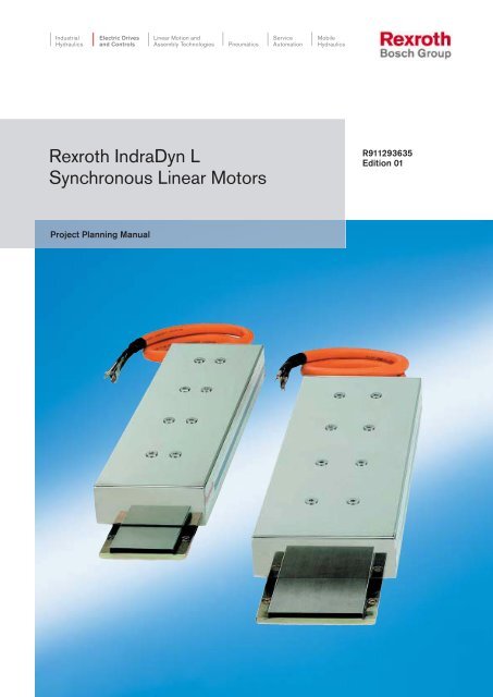
Fig. 1-1: Illustration of an <strong>IndraDyn</strong> L<br />
<strong>IndraDyn</strong>_L.jpg<br />
Due to the direct installation into the machine, there are no wearing<br />
mechanical components. This produces a power train with no or minimal<br />
backlash and permits very high control qualities with gains in the position<br />
control loop (Kv factor) of more than 20 m/min/mm.<br />
In conventional electromagnetic systems, positioning tasks with high<br />
feed rates or highly-accelerated, short-stroke movements in quick<br />
succession lead to premature wear of mechanical parts and thus to<br />
failures and significant costs. In these applications linear direct drives<br />
offer decisive advantages.
2 Introduction to the Product <strong>Rexroth</strong> <strong>IndraDyn</strong> L<br />
Performance Overview<br />
Vorschubkraft in N<br />
Feed Forces in N<br />
ORMMM<br />
OMMMM<br />
NRMMM<br />
NMMMM<br />
RMMM<br />
M<br />
21500<br />
16300<br />
11000<br />
300<br />
Considering the above-mentioned benefits, the following application are<br />
well-suited for linear synchronous direct drives:<br />
• High-speed cutting in transfer lines and machining centers<br />
• Grinding of camshafts and crankshafts<br />
• Laser machining<br />
• Precision and ultra-precision machining<br />
• Sheet-metal working<br />
• Material handling, textile and packaging machines<br />
• Free-form surface machining<br />
• Wood wooking,<br />
• Machining of printed circuit boards<br />
• ......<br />
Due to a practice-oriented combination of motor technology and<br />
intelligent digital drive controllers, the linear direct drive technique offers<br />
new solutions with significantly improved performance.<br />
The development status of the synchronous linear technique of Bosch<br />
<strong>Rexroth</strong> permits a very high force density.<br />
The spectrum of Bosch <strong>Rexroth</strong> synchronous linear drive technology,<br />
which is described below, permits feed drive systems of 250 N up to<br />
21,000 N per motor and speeds over 600 m/min.<br />
The following diagram gives an overview of the performance spectrum of<br />
the Bosch <strong>Rexroth</strong> motors type <strong>IndraDyn</strong> L.<br />
3520<br />
6720<br />
5150<br />
17750<br />
14250<br />
10900<br />
7450<br />
200<br />
2415<br />
5560<br />
7650<br />
4460<br />
3465<br />
5200<br />
140<br />
10000<br />
1680<br />
3150<br />
2415<br />
7150<br />
5600<br />
3750<br />
100<br />
1785<br />
1180<br />
2310<br />
Fig. 1-2: Performance spectrum of <strong>IndraDyn</strong> L motors<br />
3800<br />
2600<br />
2000<br />
70<br />
Dauernennkraft FdN<br />
Continuos Force F dN<br />
Maximalkraft FMax<br />
Maximum Force F Max<br />
1200<br />
820<br />
1150<br />
630 800 250<br />
40<br />
370<br />
DOK-MOTOR*-MLF********-PR01-EN-P<br />
A<br />
D<br />
C<br />
B<br />
Baugröße<br />
Size KRAFTSPEKTRUM M LF.XLS
<strong>Rexroth</strong> <strong>IndraDyn</strong> L Introduction to the Product 3<br />
1.2 About this Documentation<br />
DOK-MOTOR*-MLF********-PR01-EN-P<br />
Document Structure<br />
This documentation includes safety instructions, technical data and<br />
operating instructions. The following setup provides an overview of the<br />
contents of this documentation.<br />
Sect. Title Content<br />
1 Introduction General information<br />
2<br />
3<br />
Important Instructions on Use<br />
Safety<br />
Important safety instructions<br />
4 Technical data<br />
5 Dimensional Details<br />
6 Type Code<br />
7 Accessories<br />
8 Connection System<br />
9<br />
Operating condition and application<br />
instructions<br />
10 Motor-Controller-Combinations<br />
11 Motordimensionierung<br />
12 Handling, Transport and Storage<br />
13 Installation<br />
14 Startup, Operation and<br />
15 Service & Support<br />
16 Appendix<br />
17 Index<br />
Fig. 1-3: Chapter structure<br />
Additional documentation<br />
Product descriptions<br />
for planners and project<br />
managers<br />
Practical information<br />
Additional information<br />
for operating and maintenance<br />
personnel<br />
To plan your project using an <strong>IndraDyn</strong> L motor, you may need additional<br />
documentation depending on the complexity of your system. Bosch<br />
<strong>Rexroth</strong> provides all product documentation on CD in a PDF-format. To<br />
plan your project, you will not necessary use all the documentation<br />
included on the CD.<br />
Note: All documentation on the CD are also available in print. You<br />
can order the required product documentation through your<br />
Bosch <strong>Rexroth</strong> sales office.<br />
Material no.: Title / description<br />
R911281882 -Produktdokumentation Electric Drives and Controls Version xx 1)<br />
DOK-GENRL-CONTR*DRIVE-GNxx-DE-D650<br />
R911281883 -Product documentation Electric Drives and Controls Version xx 1)<br />
DOK-GENRL-CONTR*DRIVE-GNxx-EN-D650<br />
1) The index (e.g. ..02-...) identifies the version of the CD.<br />
Fig. 1-4: Additional documentation
4 Introduction to the Product <strong>Rexroth</strong> <strong>IndraDyn</strong> L<br />
Additional components<br />
Feedback<br />
Standards<br />
Documentation for external systems which are connected to Bosch<br />
<strong>Rexroth</strong> components are not included in the scope of delivery and must<br />
be ordered directly from the particular manufacturers.<br />
For information about the manufacturers see chapter 16 “Appendix”<br />
Your experiences are an essential part of the process of improving both<br />
product and documentation.<br />
Please do not hesitate to inform us of any mistakes you detect in this<br />
documentation or of any modifications you might desire. We would<br />
appreciate your feedback.<br />
Please send your remarks to:<br />
Bosch <strong>Rexroth</strong> AG<br />
Dept. BRC/EDM1<br />
Bürgermeister-Dr.-Nebel-Strasse 2<br />
D-97816 Lohr, Germany<br />
Fax +49 (0) 93 52 / 40-43 80<br />
This documentation refers to German, European and international<br />
technical standards. Documents and sheets on standards are subject to<br />
the protection by copyright and may not be passed on to third parties by<br />
BOSCH REXROTH AG. If necessary, please address the authorized<br />
sales outlets or, in Germany, directly to:<br />
BEUTH Verlag GmbH<br />
Burggrafenstrasse 6<br />
10787 Berlin<br />
Phone +49-(0)30-26 01-22 60, Fax +49-(0)30-26 01-12 60<br />
Internet: http://www.din.de/beuth postmaster@beuth.de<br />
DOK-MOTOR*-MLF********-PR01-EN-P
<strong>Rexroth</strong> <strong>IndraDyn</strong> L Important directions for use 2-1<br />
2 Important directions for use<br />
2.1 Appropriate use<br />
Introduction<br />
DOK-MOTOR*-MLF********-PR01-EN-P<br />
Bosch <strong>Rexroth</strong> products represent state-of-the-art developments and<br />
manufacturing. They are tested prior to delivery to ensure operating<br />
safety and reliability.<br />
The products may only be used in the manner that is defined as<br />
appropriate. If they are used in an inappropriate manner, then situations<br />
can develop that may lead to property damage or injury to personnel.<br />
Note: Bosch <strong>Rexroth</strong>, as manufacturer, is not liable for any<br />
damages resulting from inappropriate use. In such cases, the<br />
guarantee and the right to payment of damages resulting<br />
from inappropriate use are forfeited. The user alone carries<br />
all responsibility of the risks.<br />
Before using <strong>Rexroth</strong> products, make sure that all the pre-requisites for<br />
appropriate use of the products are satisfied:<br />
• Personnel that in any way, shape or form uses our products must first<br />
read and understand the relevant safety instructions and be familiar<br />
with appropriate use.<br />
• If the product takes the form of hardware, then they must remain in<br />
their original state, in other words, no structural changes are<br />
permitted. It is not permitted to decompile software products or alter<br />
source codes.<br />
• Do not mount damaged or faulty products or use them in operation.<br />
• Make sure that the products have been installed in the manner<br />
described in the relevant documentation.
2-2 Important directions for use <strong>Rexroth</strong> <strong>IndraDyn</strong> L<br />
Areas of use and application<br />
2.2 Inappropriate use<br />
<strong>Rexroth</strong> <strong>IndraDyn</strong> L motors are designed to be used as linear servo drive<br />
motors.<br />
Available for an application-specific use of the motors are unit types with<br />
differing drive power and different interfaces.<br />
Control and monitoring of the motors may require additional sensors and<br />
actors.<br />
Note: The motors may only be used with the accessories and parts<br />
specified in this document. If a component has not been<br />
specifically named, then it may not be either mounted or<br />
connected. The same applies to cables and lines.<br />
Operation is only permitted in the specified configurations<br />
and combinations of components using the software and<br />
firmware as specified in the relevant function descriptions.<br />
Every drive controller has to be programmed before starting it up,<br />
making it possible for the motor to execute the specific functions of an<br />
application.<br />
The motors may only be operated under the assembly, installation and<br />
ambient conditions as described here (temperature, protection<br />
categories, humidity, EMC requirements, etc.) and in the position<br />
specified.<br />
Using the motors outside of the above-referenced areas of application or<br />
under operating conditions other than described in the document and the<br />
technical data specified is defined as “inappropriate use".<br />
<strong>IndraDyn</strong> L motors may not be used if<br />
• they are subject to operating conditions that do not meet the above<br />
specified ambient conditions. This includes, for example, operation<br />
under water, in the case of extreme temperature fluctuations or<br />
extremely high maximum temperatures or if<br />
• Bosch <strong>Rexroth</strong> has not specifically released them for that intended<br />
purpose. Please note the specifications outlined in the general<br />
Safety Instructions!<br />
DOK-MOTOR*-MLF********-PR01-EN-P
<strong>Rexroth</strong> <strong>IndraDyn</strong> L Safety Instructions for Electric Drives and Controls 3-1<br />
3 Safety Instructions for Electric Drives and Controls<br />
3.1 Introduction<br />
3.2 Explanations<br />
DOK-MOTOR*-MLF********-PR01-EN-P<br />
Read these instructions before the initial startup of the equipment in<br />
order to eliminate the risk of bodily harm or material damage. Follow<br />
these safety instructions at all times.<br />
Do not attempt to install or start up this equipment without first reading<br />
all documentation provided with the product. Read and understand these<br />
safety instructions and all user documentation of the equipment prior to<br />
working with the equipment at any time. If you do not have the user<br />
documentation for your equipment, contact your local Bosch <strong>Rexroth</strong><br />
representative to send this documentation immediately to the person or<br />
persons responsible for the safe operation of this equipment.<br />
If the equipment is resold, rented or transferred or passed on to others,<br />
then these safety instructions must be delivered with the equipment.<br />
WARNING<br />
Improper use of this equipment, failure to follow<br />
the safety instructions in this document or<br />
tampering with the product, including disabling<br />
of safety devices, may result in material<br />
damage, bodily harm, electric shock or even<br />
death!<br />
The safety instructions describe the following degrees of hazard<br />
seriousness in compliance with ANSI Z535. The degree of hazard<br />
seriousness informs about the consequences resulting from noncompliance<br />
with the safety instructions.<br />
Warning symbol with signal<br />
word<br />
DANGER<br />
WARNING<br />
CAUTION<br />
Degree of hazard seriousness according<br />
to ANSI<br />
Death or severe bodily harm will occur.<br />
Death or severe bodily harm may occur.<br />
Bodily harm or material damage may occur.<br />
Fig. 3-1: Hazard classification (according to ANSI Z535)
3-2 Safety Instructions for Electric Drives and Controls <strong>Rexroth</strong> <strong>IndraDyn</strong> L<br />
3.3 Hazards by Improper Use<br />
DANGER<br />
DANGER<br />
WARNING<br />
WARNING<br />
CAUTION<br />
CAUTION<br />
CAUTION<br />
High voltage and high discharge current!<br />
Danger to life or severe bodily harm by electric<br />
shock!<br />
Dangerous movements! Danger to life, severe<br />
bodily harm or material damage by unintentional<br />
motor movements!<br />
High electrical voltage due to wrong<br />
connections! Danger to life or bodily harm by<br />
electric shock!<br />
Health hazard for persons with heart<br />
pacemakers, metal implants and hearing aids in<br />
proximity to electrical equipment!<br />
Surface of machine housing could be extremely<br />
hot! Danger of injury! Danger of burns!<br />
Risk of injury due to improper handling! Bodily<br />
harm caused by crushing, shearing, cutting and<br />
mechanical shock or incorrect handling of<br />
pressurized systems!<br />
Risk of injury due to incorrect handling of<br />
batteries!<br />
DOK-MOTOR*-MLF********-PR01-EN-P
<strong>Rexroth</strong> <strong>IndraDyn</strong> L Safety Instructions for Electric Drives and Controls 3-3<br />
3.4 General Information<br />
DOK-MOTOR*-MLF********-PR01-EN-P<br />
• Bosch <strong>Rexroth</strong> AG is not liable for damages resulting from failure to<br />
observe the warnings provided in this documentation.<br />
• Read the operating, maintenance and safety instructions in your<br />
language before starting up the machine. If you find that you cannot<br />
completely understand the documentation for your product, please<br />
ask your supplier to clarify.<br />
• Proper and correct transport, storage, assembly and installation as<br />
well as care in operation and maintenance are prerequisites for<br />
optimal and safe operation of this equipment.<br />
• Only persons who are trained and qualified for the use and operation<br />
of the equipment may work on this equipment or within its proximity.<br />
• The persons are qualified if they have sufficient knowledge of the<br />
assembly, installation and operation of the equipment as well as<br />
an understanding of all warnings and precautionary measures<br />
noted in these instructions.<br />
• Furthermore, they must be trained, instructed and qualified to<br />
switch electrical circuits and equipment on and off in accordance<br />
with technical safety regulations, to ground them and to mark them<br />
according to the requirements of safe work practices. They must<br />
have adequate safety equipment and be trained in first aid.<br />
• Only use spare parts and accessories approved by the manufacturer.<br />
• Follow all safety regulations and requirements for the specific<br />
application as practiced in the country of use.<br />
• The equipment is designed for installation in industrial machinery.<br />
• The ambient conditions given in the product documentation must be<br />
observed.<br />
• Use only safety features and applications that are clearly and<br />
explicitly approved in the Project Planning Manual.<br />
For example, the following areas of use are not permitted:<br />
construction cranes, elevators used for people or freight, devices and<br />
vehicles to transport people, medical applications, refinery plants,<br />
transport of hazardous goods, nuclear applications, applications<br />
sensitive to high frequency, mining, food processing, control of<br />
protection equipment (also in a machine).<br />
• The information given in the documentation of the product with<br />
regard to the use of the delivered components contains only<br />
examples of applications and suggestions.<br />
The machine and installation manufacturer must<br />
• make sure that the delivered components are suited for his<br />
individual application and check the information given in this<br />
documentation with regard to the use of the components,<br />
• make sure that his application complies with the applicable safety<br />
regulations and standards and carry out the required measures,<br />
modifications and complements.<br />
• Startup of the delivered components is only permitted once it is sure<br />
that the machine or installation in which they are installed complies<br />
with the national regulations, safety specifications and standards of<br />
the application.
3-4 Safety Instructions for Electric Drives and Controls <strong>Rexroth</strong> <strong>IndraDyn</strong> L<br />
• Operation is only permitted if the national EMC regulations for the<br />
application are met.<br />
The instructions for installation in accordance with EMC requirements<br />
can be found in the documentation "EMC in Drive and Control<br />
Systems".<br />
The machine or installation manufacturer is responsible for<br />
compliance with the limiting values as prescribed in the national<br />
regulations.<br />
• Technical data, connections and operational conditions are specified<br />
in the product documentation and must be followed at all times.<br />
3.5 Protection Against Contact with Electrical Parts<br />
Note: This section refers to equipment and drive components with<br />
voltages above 50 Volts.<br />
Touching live parts with voltages of 50 Volts and more with bare hands<br />
or conductive tools or touching ungrounded housings can be dangerous<br />
and cause electric shock. In order to operate electrical equipment,<br />
certain parts must unavoidably have dangerous voltages applied to<br />
them.<br />
DOK-MOTOR*-MLF********-PR01-EN-P
<strong>Rexroth</strong> <strong>IndraDyn</strong> L Safety Instructions for Electric Drives and Controls 3-5<br />
DOK-MOTOR*-MLF********-PR01-EN-P<br />
DANGER<br />
High electrical voltage! Danger to life, severe<br />
bodily harm by electric shock!<br />
⇒ Only those trained and qualified to work with or on<br />
electrical equipment are permitted to operate, maintain<br />
or repair this equipment.<br />
⇒ Follow general construction and safety regulations<br />
when working on high voltage installations.<br />
⇒ Before switching on power the ground wire must be<br />
permanently connected to all electrical units according<br />
to the connection diagram.<br />
⇒ Do not operate electrical equipment at any time, even<br />
for brief measurements or tests, if the ground wire is<br />
not permanently connected to the points of the<br />
components provided for this purpose.<br />
⇒ Before working with electrical parts with voltage higher<br />
than 50 V, the equipment must be disconnected from<br />
the mains voltage or power supply. Make sure the<br />
equipment cannot be switched on again unintended.<br />
⇒ The following should be observed with electrical drive<br />
and filter components:<br />
⇒ Wait five (5) minutes after switching off power to allow<br />
capacitors to discharge before beginning to work.<br />
Measure the voltage on the capacitors before<br />
beginning to work to make sure that the equipment is<br />
safe to touch.<br />
⇒ Never touch the electrical connection points of a<br />
component while power is turned on.<br />
⇒ Install the covers and guards provided with the<br />
equipment properly before switching the equipment on.<br />
Prevent contact with live parts at any time.<br />
⇒ A residual-current-operated protective device (RCD)<br />
must not be used on electric drives! Indirect contact<br />
must be prevented by other means, for example, by an<br />
overcurrent protective device.<br />
⇒ Electrical components with exposed live parts and<br />
uncovered high voltage terminals must be installed in a<br />
protective housing, for example, in a control cabinet.
3-6 Safety Instructions for Electric Drives and Controls <strong>Rexroth</strong> <strong>IndraDyn</strong> L<br />
To be observed with electrical drive and filter components:<br />
DANGER<br />
High electrical voltage on the housing!<br />
High leakage current! Danger to life, danger of<br />
injury by electric shock!<br />
⇒ Connect the electrical equipment, the housings of all<br />
electrical units and motors permanently with the<br />
safety conductor at the ground points before power is<br />
switched on. Look at the connection diagram. This is<br />
even necessary for brief tests.<br />
⇒ Connect the safety conductor of the electrical<br />
equipment always permanently and firmly to the<br />
supply mains. Leakage current exceeds 3.5 mA in<br />
normal operation.<br />
⇒ Use a copper conductor with at least 10 mm² cross<br />
section over its entire course for this safety conductor<br />
connection!<br />
⇒ Prior to startups, even for brief tests, always connect<br />
the protective conductor or connect with ground wire.<br />
Otherwise, high voltages can occur on the housing<br />
that lead to electric shock.<br />
3.6 Protection Against Electric Shock by Protective Low<br />
Voltage (PELV)<br />
All connections and terminals with voltages between 0 and 50 Volts on<br />
<strong>Rexroth</strong> products are protective low voltages designed in accordance<br />
with international standards on electrical safety.<br />
WARNING<br />
High electrical voltage due to wrong<br />
connections! Danger to life, bodily harm by<br />
electric shock!<br />
⇒ Only connect equipment, electrical components and<br />
cables of the protective low voltage type (PELV =<br />
Protective Extra Low Voltage) to all terminals and<br />
clamps with voltages of 0 to 50 Volts.<br />
⇒ Only electrical circuits may be connected which are<br />
safely isolated against high voltage circuits. Safe<br />
isolation is achieved, for example, with an isolating<br />
transformer, an opto-electronic coupler or when<br />
battery-operated.<br />
DOK-MOTOR*-MLF********-PR01-EN-P
<strong>Rexroth</strong> <strong>IndraDyn</strong> L Safety Instructions for Electric Drives and Controls 3-7<br />
3.7 Protection Against Dangerous Movements<br />
DOK-MOTOR*-MLF********-PR01-EN-P<br />
Dangerous movements can be caused by faulty control of the connected<br />
motors. Some common examples are:<br />
• improper or wrong wiring of cable connections<br />
• incorrect operation of the equipment components<br />
• wrong input of parameters before operation<br />
• malfunction of sensors, encoders and monitoring devices<br />
• defective components<br />
• software or firmware errors<br />
Dangerous movements can occur immediately after equipment is<br />
switched on or even after an unspecified time of trouble-free operation.<br />
The monitoring in the drive components will normally be sufficient to<br />
avoid faulty operation in the connected drives. Regarding personal<br />
safety, especially the danger of bodily injury and material damage, this<br />
alone cannot be relied upon to ensure complete safety. Until the<br />
integrated monitoring functions become effective, it must be assumed in<br />
any case that faulty drive movements will occur. The extent of faulty<br />
drive movements depends upon the type of control and the state of<br />
operation.
3-8 Safety Instructions for Electric Drives and Controls <strong>Rexroth</strong> <strong>IndraDyn</strong> L<br />
DANGER<br />
Dangerous movements! Danger to life, risk of<br />
injury, severe bodily harm or material damage!<br />
⇒ Ensure personal safety by means of qualified and<br />
tested higher-level monitoring devices or measures<br />
integrated in the installation. Unintended machine<br />
motion is possible if monitoring devices are disabled,<br />
bypassed or not activated.<br />
⇒ Pay attention to unintended machine motion or other<br />
malfunction in any mode of operation.<br />
⇒ Keep free and clear of the machine’s range of motion<br />
and moving parts. Possible measures to prevent<br />
people from accidentally entering the machine’s<br />
range of motion:<br />
- use safety fences<br />
- use safety guards<br />
- use protective coverings<br />
- install light curtains or light barriers<br />
⇒ Fences and coverings must be strong enough to<br />
resist maximum possible momentum, especially if<br />
there is a possibility of loose parts flying off.<br />
⇒ Mount the emergency stop switch in the immediate<br />
reach of the operator. Verify that the emergency stop<br />
works before startup. Don’t operate the machine if<br />
the emergency stop is not working.<br />
⇒ Isolate the drive power connection by means of an<br />
emergency stop circuit or use a starting lockout to<br />
prevent unintentional start.<br />
⇒ Make sure that the drives are brought to a safe<br />
standstill before accessing or entering the danger<br />
zone. Safe standstill can be achieved by switching off<br />
the power supply contactor or by safe mechanical<br />
locking of moving parts.<br />
⇒ Secure vertical axes against falling or dropping after<br />
switching off the motor power by, for example:<br />
- mechanically securing the vertical axes<br />
- adding an external braking/ arrester/ clamping<br />
mechanism<br />
- ensuring sufficient equilibration of the vertical<br />
axes<br />
The standard equipment motor brake or an external<br />
brake controlled directly by the drive controller are<br />
not sufficient to guarantee personal safety!<br />
DOK-MOTOR*-MLF********-PR01-EN-P
<strong>Rexroth</strong> <strong>IndraDyn</strong> L Safety Instructions for Electric Drives and Controls 3-9<br />
DOK-MOTOR*-MLF********-PR01-EN-P<br />
⇒ Disconnect electrical power to the equipment using a<br />
master switch and secure the switch against<br />
reconnection for:<br />
- maintenance and repair work<br />
- cleaning of equipment<br />
- long periods of discontinued equipment use<br />
⇒ Prevent the operation of high-frequency, remote<br />
control and radio equipment near electronics circuits<br />
and supply leads. If the use of such equipment<br />
cannot be avoided, verify the system and the<br />
installation for possible malfunctions in all possible<br />
positions of normal use before initial startup. If<br />
necessary, perform a special electromagnetic<br />
compatibility (EMC) test on the installation.<br />
3.8 Protection Against Magnetic and Electromagnetic Fields<br />
During Operation and Mounting<br />
Magnetic and electromagnetic fields generated near current-carrying<br />
conductors and permanent magnets in motors represent a serious health<br />
hazard to persons with heart pacemakers, metal implants and hearing<br />
aids.<br />
WARNING<br />
Health hazard for persons with heart<br />
pacemakers, metal implants and hearing aids in<br />
proximity to electrical equipment!<br />
⇒ Persons with heart pacemakers, hearing aids and<br />
metal implants are not permitted to enter the<br />
following areas:<br />
- Areas in which electrical equipment and parts are<br />
mounted, being operated or started up.<br />
- Areas in which parts of motors with permanent<br />
magnets are being stored, operated, repaired or<br />
mounted.<br />
⇒ If it is necessary for a person with a heart pacemaker<br />
to enter such an area, then a doctor must be<br />
consulted prior to doing so. Heart pacemakers that<br />
are already implanted or will be implanted in the<br />
future, have a considerable variation in their electrical<br />
noise immunity. Therefore there are no rules with<br />
general validity.<br />
⇒ Persons with hearing aids, metal implants or metal<br />
pieces must consult a doctor before they enter the<br />
areas described above. Otherwise, health hazards<br />
will occur.
3-10 Safety Instructions for Electric Drives and Controls <strong>Rexroth</strong> <strong>IndraDyn</strong> L<br />
3.9 Protection Against Contact with Hot Parts<br />
CAUTION<br />
Housing surfaces could be extremely hot!<br />
Danger of injury! Danger of burns!<br />
⇒ Do not touch housing surfaces near sources of heat!<br />
Danger of burns!<br />
⇒ After switching the equipment off, wait at least ten<br />
(10) minutes to allow it to cool down before touching<br />
it.<br />
⇒ Do not touch hot parts of the equipment, such as<br />
housings with integrated heat sinks and resistors.<br />
Danger of burns!<br />
3.10 Protection During Handling and Mounting<br />
3.11 Battery Safety<br />
Under certain conditions, incorrect handling and mounting of parts and<br />
components may cause injuries.<br />
CAUTION<br />
Risk of injury by incorrect handling! Bodily harm<br />
caused by crushing, shearing, cutting and<br />
mechanical shock!<br />
⇒ Observe general installation and safety instructions<br />
with regard to handling and mounting.<br />
⇒ Use appropriate mounting and transport equipment.<br />
⇒ Take precautions to avoid pinching and crushing.<br />
⇒ Use only appropriate tools. If specified by the product<br />
documentation, special tools must be used.<br />
⇒ Use lifting devices and tools correctly and safely.<br />
⇒ For safe protection wear appropriate protective<br />
clothing, e.g. safety glasses, safety shoes and safety<br />
gloves.<br />
⇒ Never stand under suspended loads.<br />
⇒ Clean up liquids from the floor immediately to prevent<br />
slipping.<br />
Batteries contain reactive chemicals in a solid housing. Inappropriate<br />
handling may result in injuries or material damage.<br />
DOK-MOTOR*-MLF********-PR01-EN-P
<strong>Rexroth</strong> <strong>IndraDyn</strong> L Safety Instructions for Electric Drives and Controls 3-11<br />
DOK-MOTOR*-MLF********-PR01-EN-P<br />
CAUTION<br />
Risk of injury by incorrect handling!<br />
⇒ Do not attempt to reactivate discharged batteries by<br />
heating or other methods (danger of explosion and<br />
cauterization).<br />
⇒ Never charge non-chargeable batteries (danger of<br />
leakage and explosion).<br />
⇒ Never throw batteries into a fire.<br />
⇒ Do not dismantle batteries.<br />
⇒ Do not damage electrical components installed in the<br />
equipment.<br />
Note: Be aware of environmental protection and disposal! The<br />
batteries contained in the product should be considered as<br />
hazardous material for land, air and sea transport in the<br />
sense of the legal requirements (danger of explosion).<br />
Dispose batteries separately from other waste. Observe the<br />
legal requirements in the country of installation.<br />
3.12 Protection Against Pressurized Systems<br />
Certain motors and drive controllers, corresponding to the information in<br />
the respective Project Planning Manual, must be provided with<br />
pressurized media, such as compressed air, hydraulic oil, cooling fluid<br />
and cooling lubricant supplied by external systems. Incorrect handling of<br />
the supply and connections of pressurized systems can lead to injuries<br />
or accidents. In these cases, improper handling of external supply<br />
systems, supply lines or connections can cause injuries or material<br />
damage.<br />
CAUTION<br />
Danger of injury by incorrect handling of<br />
pressurized systems !<br />
⇒ Do not attempt to disassemble, to open or to cut a<br />
pressurized system (danger of explosion).<br />
⇒ Observe the operation instructions of the respective<br />
manufacturer.<br />
⇒ Before disassembling pressurized systems, release<br />
pressure and drain off the fluid or gas.<br />
⇒ Use suitable protective clothing (for example safety<br />
glasses, safety shoes and safety gloves)<br />
⇒ Remove any fluid that has leaked out onto the floor<br />
immediately.<br />
Note: Environmental protection and disposal! The media used in<br />
the operation of the pressurized system equipment may not<br />
be environmentally compatible. Media that are damaging the<br />
environment must be disposed separately from normal waste.<br />
Observe the legal requirements in the country of installation.
3-12 Safety Instructions for Electric Drives and Controls <strong>Rexroth</strong> <strong>IndraDyn</strong> L<br />
Notes<br />
DOK-MOTOR*-MLF********-PR01-EN-P
<strong>Rexroth</strong> <strong>IndraDyn</strong> L Technical Data <strong>IndraDyn</strong> L 1<br />
4 Technical Data <strong>IndraDyn</strong> L<br />
4.1 Explanation to technical data<br />
DOK-MOTOR*-MLF********-PR01-EN-P<br />
All relevant technical motor data as well as the functional principle of<br />
these motors are given on the following pages in terms of tables and<br />
characteristic curves. The following parameters will be taken into<br />
consideration :<br />
• Size and length of the primary<br />
• Type of winding of the primary<br />
• Available power supply or DC link voltage<br />
Note: Unless otherwise noted, all data and characteristic curves are<br />
based on the following conditions:<br />
• Motor-winding temperature of 135°C.<br />
• Nominal air gap<br />
• Cooling with water with a supply temperature of 30°C<br />
Note: Resulting data from certain motor-controller combinations can<br />
differ from the given data. See Chapter 10 “Motor-controller<br />
combinations”.<br />
Characteristic force/speed curve<br />
The characteristic force vs. speed curve is given shows the limiting<br />
curve. The shapes of these characteristic curves are defined by the DC<br />
bus voltage and the relevant motor-specific data, e.g. inductivity,<br />
resistance and the motor constants. Varying the DC bus voltage (using<br />
different drives, power supplies or supply voltages) and/or using different<br />
motor windings will result in different characteristic curves (see Fig. 4-1).
2 Technical Data <strong>IndraDyn</strong> L <strong>Rexroth</strong> <strong>IndraDyn</strong> L<br />
force<br />
F max<br />
F dN<br />
1 2 3 4 5<br />
VFMAX V N velocity<br />
FVKENNLIN-MLF-EN.EPS<br />
[1]: 3 x 400V providing an unregulated DC bus voltage, UDC = 540V<br />
(Possible with an HCS compact drive controller or with an HMS or<br />
HMD drive controller in combination with an HMV power supply)<br />
[2]: 3 x 440V providing an unregulated DC bus voltage, UDC = 600V<br />
(Possible with an HCS compact drive controller or with an HMS or<br />
HMD drive controller in combination with an HMV power supply)<br />
[3]: 3 x 480V providing an unregulated DC bus voltage, UDC = 650V<br />
(Possible with an HCS compact drive controller or with an HMS or<br />
HMD drive controller in combination with an HMV power supply)<br />
[4]: 3 x 480V providing an regulated DC bus voltage, UDC = 650V<br />
(Possible with an HMS or HMD drive controller in combination with<br />
an HMV power supply)<br />
[5]: 3 x 400....480V providing an regulated DC bus voltage, UDC = 750V<br />
(Possible with an HMS or HMD drive controller in combination with<br />
an HMV power supply)<br />
Fig. 4-1: Characteristic force vs. Speed curve<br />
The maximum force, FMAX, is available up to a limited velocity, vFMAX.<br />
When the velocity rises, the available DC bus voltage is reduced by the<br />
velocity-dependent Back EMF of the motor. This leads to a reduction of<br />
the maximum feed force at higher velocities. The characteristic curves<br />
are specified up to the continuous nominal force. The velocity that<br />
belongs to the continuous nominal force is known as nominal velocity,<br />
vN.<br />
Note: If the connection voltages or mains voltages are different, the<br />
specified characteristic curves can be converted linearly<br />
according to the existing voltages.<br />
Where power supply modules with unregulated DC bus<br />
voltage are concerned, voltage drops – from simultaneous<br />
acceleration of several axes, for example - must be taken into<br />
consideration.<br />
DOK-MOTOR*-MLF********-PR01-EN-P
<strong>Rexroth</strong> <strong>IndraDyn</strong> L Technical Data <strong>IndraDyn</strong> L 3<br />
Parallel connection of two<br />
primaries on one drive controller<br />
DOK-MOTOR*-MLF********-PR01-EN-P<br />
The following interrelations exist for the parallel connection of two<br />
primaries on one drive controller:<br />
• Doubling of currents and feed forces<br />
(unless limited by the drive controller)<br />
• Velocities vFMAX and vNENN as in single arrangement<br />
• Same motor and voltage constants (kiF, kE)<br />
• Halved motor resistances and inductances.<br />
feed force<br />
F max<br />
F dN<br />
parallel arrangement<br />
F max<br />
F dN<br />
single arrangement<br />
VFMAX<br />
velocity<br />
V N<br />
FVKENNLIN1-MLF-EN.EPS<br />
Fig. 4-2: Characteristic force vs. Speed curves for single and parallel<br />
connection of primaries to one drive controller<br />
Note: To facilitate the commissioning of parallel connection of two<br />
primaries to one drive controller, this document has<br />
corresponding selection data for motor – controller<br />
combinations and the motor parameters (see chapter 10<br />
“Motor – Controller Combinations” and Chapter 14<br />
“Commissioning”)
4 Technical Data <strong>IndraDyn</strong> L <strong>Rexroth</strong> <strong>IndraDyn</strong> L<br />
4.2 Technical data – size 040<br />
Description Symbol Unit MLP040<br />
Motor data 1 )<br />
Frame length A B<br />
Winding code 0300 0150 0250 0300<br />
Corresponding secondaries MLS040S-3A-****-NNNN<br />
Maximum force 2)<br />
Fmax N 800 1150<br />
Continuous nominal force FdN N 250 370<br />
Max. current imax A 20 20 27 35<br />
Continuous current idN A 4.2 4.2 5.3 6<br />
Maximum speed with Fmax 3)<br />
vFmax m/min 300 150 250 300<br />
Nominal velocity 3)<br />
vN m/min 500 300 400 500<br />
Force constant KiFN N/A 60 88 70 62<br />
Voltage constant 4)<br />
KEMF Vs/m in preparation<br />
Winding resistance at 20°C R12 Ohm 8.6 i.p. i.p. 5.1<br />
Winding inductivety L12 mH 54.2 i.p. i.p. 33.2<br />
Minimum cross-section of connection cable 5)<br />
APL mm² 1<br />
Rated power loss PvN W 400 550<br />
Nominal air gap δ mm 1.0 ±0.4<br />
Attractive force 6)<br />
FATT N 1200 1700<br />
Mass of primary - standard encapsulation mPS kg 4.7 6.1<br />
Mass of primary - thermal encapsulation mPT kg 6.1 8.1<br />
Unit mass if secondary mS kg/m 5.4<br />
Required coolant flow ∆ϑN 10)<br />
Qmin l/min 0.57 0.79<br />
standard encapsulation<br />
Pressure loss constant<br />
0.16 0.16<br />
7)<br />
thermal encapsulation<br />
kdp<br />
0.16 0.16<br />
Pressure loss at QN<br />
standard encapsulation<br />
thermal encapsulation<br />
∆p bar<br />
0.06<br />
0.06<br />
0.10<br />
0.11<br />
Coolant inlet temperature 8)<br />
ϑin °C +15...+40<br />
Temperature rise at PvN 9)<br />
∆ϑN K 10<br />
Thermal time constant Tth min in preparation<br />
Permissible temperature of secondary TSmax °C 70<br />
Permissible ambient temperature Tum °C 0...+45<br />
Permissible storage and transport temperature TL °C -10...+60<br />
Protection class IP65<br />
Insulation class acc. to DIN VDE 0530-1 F<br />
Housing surface of primary<br />
-FT-: Priming black (RAL 9005)<br />
-FS-: stainless steel blank / priming black (RAL 9005)<br />
1<br />
)<br />
2<br />
)<br />
The measured values are effective values acc. to IEC 60034-1, unless other values are given. Reference value is 540 VDC.<br />
The maximum obtainable force depends on the drive controller.<br />
3<br />
) The obtain velocity depends on the DC bus voltage.<br />
4<br />
)<br />
-1<br />
EMF=Electromagnetic force. Effective value refer to 1 min .<br />
5<br />
) Dimensioned to EN 60204-1(1993), laying system B2 and conversion factor for Bosch <strong>Rexroth</strong> cable at 40°C environmental<br />
temperature. When using other cables, other cross-sections may be required. For additional notes to connection and power cables<br />
see Chapter 8.1.<br />
6<br />
) Nominal air gap between primary and secondary, No voltage applied to primary, see Chapter 9.5.<br />
7<br />
) Coolant medium is water. Actual pressure loss is dependent on the coolant flow, see Chapter 9.6.<br />
8<br />
) The coolant inlet temperature may be max. 5°K under the ambient temperature due to danger of condensation!<br />
9<br />
) Operation with liquid cooling using water as coolant with a supply temperature of 30°C.<br />
10<br />
) For further notes see Chapter 9.6 “Motor coolant, flow rate“.<br />
Fig. 4-3: Data sheet motor size 040<br />
DOK-MOTOR*-MLF********-PR01-EN-P
<strong>Rexroth</strong> <strong>IndraDyn</strong> L Technical Data <strong>IndraDyn</strong> L 5<br />
4.3 Technical data – size 070<br />
Description<br />
Motor data<br />
Symbol Unit MLP070<br />
1)<br />
Frame length A B<br />
Winding code 0150 0220 0300 0100 0120 0150 0250 0300<br />
Corresponding secondaries MLS070S-3A-****-NNNN<br />
Maximum force 2)<br />
Fmax N 2000 2600<br />
Continuous nominal force FdN N 630 820<br />
Max. current imax A 27 35 55 28 42 48 55 70<br />
Continuous current idN A 5.3 6.3 10.5 5.5 5.8 6.2 10 12<br />
Maximum speed with Fmax 3)<br />
vFmax m/mi 150 220 300 100 120 150 250 300<br />
Nominal velocity 3)<br />
vN m/mi 250 360 450 200 220 260 400 450<br />
Force constant KiFN N/A 119 100 60 149 141 132 82 68<br />
Voltage constant 4)<br />
KEMF Vs/ i.p. i.p. 20 i.p. 80 i.p. i.p. i.p.<br />
Winding resistance at 20°C R12 Ohm i.p. i.p. 2.8 i.p. 9.2 i.p. i.p. i.p.<br />
Winding inductivety L12 mH i.p. i.p. 14.3 i.p. 51.6 i.p. i.p. i.p.<br />
Minimum cross-section of connection cable 5)<br />
APL mm² 1<br />
Rated power loss PvN W 780 900<br />
Nominal air gap δ mm 1.0 ±0.4<br />
Attractive force 6)<br />
FATT N 2900 3750<br />
Mass of primary - standard encapsulation mPS kg 8.4 10.4<br />
Mass of primary - thermal encapsulation mPT kg 10.9 13.4<br />
Unit mass if secondary mS kg/m 9.4<br />
Required coolant flow ∆ϑN 10)<br />
Qmin l/min 1.12 1.29<br />
standard encapsulation<br />
Pressure loss constant<br />
0.18 0.18<br />
7)<br />
thermal encapsulation<br />
kdp<br />
0.18 0.18<br />
Pressure loss at QN<br />
standard encapsulation<br />
thermal encapsulation<br />
∆p bar<br />
0.22<br />
0.22<br />
0.28<br />
0.29<br />
Coolant inlet temperature 8)<br />
ϑin °C +15...+40<br />
Temperature rise at PvN 9)<br />
∆ϑN K 10<br />
Thermal time constant Tth min 6 5.7<br />
Permissible temperature of secondary TSmax °C 70<br />
Permissible ambient temperature Tum °C 0...+45<br />
Permissible storage and transport temperature TL °C -10...+60<br />
Protection class IP65<br />
Insulation class acc. to DIN VDE 0530-1 F<br />
Housing surface of primary<br />
-FT-:<br />
-FS-:<br />
Priming black (RAL 9005)<br />
stainless steel blank / priming black (RAL 9005)<br />
1<br />
)<br />
2<br />
)<br />
The measured values are effective values acc. to IEC 60034-1, unless other values are given. Reference value is 540 VDC.<br />
The maximum obtainable force depends on the drive controller.<br />
3<br />
) The obtain velocity depends on the DC bus voltage.<br />
4<br />
)<br />
-1<br />
EMF=Electromagnetic force. Effective value refer to 1 min .<br />
5<br />
) Dimensioned to EN 60204-1(1993), laying system B2 and conversion factor for Bosch <strong>Rexroth</strong> cable at 40°C environmental<br />
temperature. When using other cables, other cross-sections may be required. For additional notes to connection and power cables<br />
see Chapter 8.1.<br />
6<br />
) Nominal air gap between primary and secondary, No voltage applied to primary, see Chapter 9.5.<br />
7<br />
) Coolant medium is water. Actual pressure loss is dependent on the coolant flow, see Chapter 9.6.<br />
8<br />
) The coolant inlet temperature may be max. 5°K under the ambient temperature due to danger of condensation!<br />
9<br />
) Operation with liquid cooling using water as coolant with a supply temperature of 30°C.<br />
10<br />
) For further notes see Chapter 9.6 “Motor coolant, flow rate“.<br />
DOK-MOTOR*-MLF********-PR01-EN-P<br />
Fig. 4-4: Data sheet motor size 070(1/2)
6 Technical Data <strong>IndraDyn</strong> L <strong>Rexroth</strong> <strong>IndraDyn</strong> L<br />
Description Symbol Unit MLP070<br />
Motor data 1)<br />
Frame length C<br />
Winding code 0120 0150 0240 0300<br />
Corresponding secondaries MLS070S-3A-****-NNNN<br />
Maximum force 2)<br />
Fmax N 3800<br />
Continuous nominal force FdN N 1200<br />
Max. current imax A 55 62 70 110<br />
Continuous current idN A 8.9 10 13 19<br />
Maximum speed with Fmax 3)<br />
vFmax m/min 120 150 240 300<br />
Nominal velocity 3)<br />
vN m/min 180 250 350 450<br />
Force constant KiFN N/A 135 120 92 63<br />
Voltage constant 4)<br />
KEMF Vs/m 78 i.p. i.p. i.p.<br />
Winding resistance at 20°C R12 Ohm 5.7 i.p. i.p. 1.5<br />
Winding inductivety L12 mH 33.9 i.p. i.p. 12.3<br />
Minimum cross-section of connection cable 5)<br />
APL mm² 1 2.5<br />
Rated power loss PvN W 1100<br />
Nominal air gap δ mm 1.0 ±0.4<br />
Attractive force 6)<br />
FATT N 5500<br />
Mass of primary - standard encapsulation mPS kg 14.5<br />
Mass of primary - thermal encapsulation mPT kg 18.4<br />
Unit mass if secondary mS kg/m 9.4<br />
Required coolant flow ∆ϑN 10)<br />
Qmin l/min 1.58<br />
standard encapsulation<br />
Pressure loss constant<br />
0.19<br />
7)<br />
thermal encapsulation<br />
kdp<br />
0.19<br />
Pressure loss at QN<br />
standard encapsulation<br />
thermal encapsulation<br />
∆p bar<br />
0.43<br />
0.43<br />
Coolant inlet temperature 8)<br />
ϑin °C +15...+40<br />
Temperature rise at PvN 9)<br />
∆ϑN K 10<br />
Thermal time constant Tth min 7.5<br />
Permissible temperature of secondary TSmax °C 70<br />
Permissible ambient temperature Tum °C 0...+45<br />
Permissible storage and transport temperature TL °C -10...+60<br />
Protection class IP65<br />
Insulation class acc. to DIN VDE 0530-1 F<br />
Housing surface of primary<br />
-FT-:<br />
-FS-:<br />
Priming black (RAL 9005)<br />
stainless steel blank / priming black (RAL 9005)<br />
1<br />
)<br />
2<br />
)<br />
The measured values are effective values acc. to IEC 60034-1, unless other values are given. Reference value is 540 VDC.<br />
The maximum obtainable force depends on the drive controller.<br />
3<br />
) The obtain velocity depends on the DC bus voltage.<br />
4<br />
)<br />
-1<br />
EMF=Electromagnetic force. Effective value refer to 1 min .<br />
5<br />
) Dimensioned to EN 60204-1(1993), laying system B2 and conversion factor for Bosch <strong>Rexroth</strong> cable at 40°C environmental<br />
temperature. When using other cables, other cross-sections may be required. For additional notes to connection and power cables<br />
see Chapter 8.1.<br />
6<br />
) Nominal air gap between primary and secondary, No voltage applied to primary, see Chapter 9.5.<br />
7<br />
) Coolant medium is water. Actual pressure loss is dependent on the coolant flow, see Chapter 9.6.<br />
8<br />
) The coolant inlet temperature may be max. 5°K under the ambient temperature due to danger of condensation!<br />
9<br />
) Operation with liquid cooling using water as coolant with a supply temperature of 30°C.<br />
10<br />
) For further notes see Chapter 9.6 “Motor coolant, flow rate“.<br />
Fig. 4-5: Data sheet motor size 070(2/2)<br />
DOK-MOTOR*-MLF********-PR01-EN-P
<strong>Rexroth</strong> <strong>IndraDyn</strong> L Technical Data <strong>IndraDyn</strong> L 7<br />
4.4 Technical data – size 100<br />
Description Symbol Unit MLP100<br />
Motor data 1)<br />
Frame length A B C<br />
Winding code 0090 0120 0150 0190 0120 0250 0090 0120 0190<br />
Corresponding secondaries MLS100S-3A-****-NNNN<br />
Maximum force 2)<br />
Fmax N 3750 5600 7150<br />
Continuous nominal force FdN N 1180 1785 2310<br />
Max. current imax A 38 44 55 70 70 130 70 85 140<br />
Continuous current idN A 6.6 8 10 12 12 22 13 15 23<br />
Maximum speed with Fmax 3)<br />
vFmax m/mi 90 120 150 190 120 250 90 120 190<br />
Nominal velocity 3)<br />
vN m/mi 150 190 220 290 190 350 170 190 290<br />
Force constant KiFN N/A 169 148 118 98 149 81 178 154 100<br />
Voltage constant 4)<br />
KEMF Vs/ i.p. i.p. i.p. i.p. 87 i.p. i.p. 89 i.p.<br />
Winding resistance at 20°C R12 Ohm 8.8 8 i.p. i.p. 4.45 i.p. i.p. 3.8 i.p.<br />
Winding inductivety L12 mH 55 49 i.p. i.p. 25 i.p. i.p. 21.1 i.p.<br />
Minimum cross-section of connection cable 5)<br />
APL mm² 1 2.5 1 1.5 4<br />
Rated power loss PvN W 900 1300 1600<br />
Nominal air gap δ mm 1.0 ±0.4<br />
Attractive force 6)<br />
FATT N 5400 8000 10400<br />
Mass of primary - standard encapsulation mPS kg 13.5 18.7 24<br />
Mass of primary - thermal encapsulation mPT kg 17 23.3 29.7<br />
Unit mass if secondary mS kg/m 13.4<br />
Required coolant flow ∆ϑN 10)<br />
Qmin l/min 1.29 1.87 2.3<br />
standard encapsulation<br />
Pressure loss constant<br />
0.19 0.18 0.19<br />
7)<br />
thermal encapsulation<br />
kdp<br />
0.19 0.18 0.19<br />
Pressure loss at QN<br />
standard encapsulation<br />
thermal encapsulation<br />
∆p bar<br />
0.29<br />
0.3<br />
0.52<br />
0.54<br />
0.8<br />
0.82<br />
Coolant inlet temperature 8)<br />
ϑin °C +15...+40<br />
Temperature rise at PvN 9)<br />
∆ϑN K 10<br />
Thermal time constant Tth min i.p. 7 6.8<br />
Permissible temperature of secondary TSmax °C 70<br />
Permissible ambient temperature Tum °C 0...+45<br />
Permissible storage and transport temperature TL °C -10...+60<br />
Protection class IP65<br />
Insulation class acc. to DIN VDE 0530-1 F<br />
Housing surface of primary<br />
-FT-:<br />
-FS-:<br />
Priming black (RAL 9005)<br />
stainless steel blank / priming black (RAL 9005)<br />
1<br />
)<br />
2<br />
)<br />
The measured values are effective values acc. to IEC 60034-1, unless other values are given. Reference value is 540 VDC.<br />
The maximum obtainable force depends on the drive controller.<br />
3<br />
) The obtain velocity depends on the DC bus voltage.<br />
4<br />
)<br />
-1<br />
EMF=Electromagnetic force. Effective value refer to 1 min .<br />
5<br />
) Dimensioned to EN 60204-1(1993), laying system B2 and conversion factor for Bosch <strong>Rexroth</strong> cable at 40°C environmental<br />
temperature. When using other cables, other cross-sections may be required. For additional notes to connection and power cables<br />
see Chapter 8.1.<br />
6<br />
) Nominal air gap between primary and secondary, No voltage applied to primary, see Chapter 9.5.<br />
7<br />
) Coolant medium is water. Actual pressure loss is dependent on the coolant flow, see Chapter 9.6.<br />
8<br />
) The coolant inlet temperature may be max. 5°K under the ambient temperature due to danger of condensation!<br />
9<br />
) Operation with liquid cooling using water as coolant with a supply temperature of 30°C.<br />
10<br />
) For further notes see Chapter 9.6 “Motor coolant, flow rate“.<br />
DOK-MOTOR*-MLF********-PR01-EN-P<br />
Fig. 4-6: Data sheet size 100
8 Technical Data <strong>IndraDyn</strong> L <strong>Rexroth</strong> <strong>IndraDyn</strong> L<br />
4.5 Technical data – size 140<br />
Description Symbol Unit MLP140<br />
Motor data 1)<br />
Frame length A B C<br />
Winding code 0120 0090 0120 0050 0120 0170<br />
Corresponding secondaries MLS140S-3A-****-NNNN<br />
Maximum force 2)<br />
Fmax N 5200 7650 10000<br />
Continuous nominal force FdN N 1680 2415 3150<br />
Max. current imax A 70 70 105 70 125 140<br />
Continuous current idN A 12 13 18 13 21 29<br />
Maximum speed with Fmax 3)<br />
vFmax m/min 120 90 120 50 120 170<br />
Nominal velocity 3)<br />
vN m/min 190 160 190 110 190 250<br />
Force constant KiFN N/A 140 186 134 242 150 109<br />
Voltage constant 4)<br />
KEMF Vs/m i.p. i.p. i.p. i.p. i.p. i.p.<br />
Winding resistance at 20°C R12 Ohm 4 i.p. 2.6 i.p. 2.6 i.p.<br />
Winding inductivety L12 mH 28.2 i.p. 19.8 i.p. 12.3 i.p.<br />
Minimum cross-section of connection cable 5)<br />
APL mm² 1 2.5 1 2.5 4<br />
Rated power loss PvN W 1300 1700 2000<br />
Nominal air gap δ mm 1.0 ±0.4<br />
Attractive force 6)<br />
FATT N 7500 11000 14400<br />
Mass of primary - standard encapsulation mPS kg 17 24.5 32<br />
Mass of primary - thermal encapsulation mPT kg 21.2 30.1 38.9<br />
Unit mass if secondary mS kg/m 18.8<br />
Required coolant flow ∆ϑN 10)<br />
Qmin l/min 1.87 2.44 2.87<br />
standard encapsulation<br />
Pressure loss constant<br />
0.18 0.18 0.18<br />
7)<br />
thermal encapsulation<br />
kdp<br />
0.19 0.19 0.19<br />
Pressure loss at QN<br />
standard encapsulation<br />
thermal encapsulation<br />
∆p bar<br />
0.54<br />
0.56<br />
0.87<br />
0.89<br />
1.15<br />
1.18<br />
Coolant inlet temperature 8)<br />
ϑin °C +15...+40<br />
Temperature rise at PvN 9)<br />
∆ϑN K 10<br />
Thermal time constant Tth min in preparation<br />
Permissible temperature of secondary TSmax °C 70<br />
Permissible ambient temperature Tum °C 0...+45<br />
Permissible storage and transport temperature TL °C -10...+60<br />
Protection class IP65<br />
Insulation class acc. to DIN VDE 0530-1 F<br />
Housing surface of primary<br />
-FT-:<br />
-FS-:<br />
Priming black (RAL 9005)<br />
stainless steel blank / priming black (RAL 9005)<br />
1<br />
)<br />
2<br />
)<br />
The measured values are effective values acc. to IEC 60034-1, unless other values are given. Reference value is 540 VDC.<br />
The maximum obtainable force depends on the drive controller.<br />
3<br />
) The obtain velocity depends on the DC bus voltage.<br />
4<br />
)<br />
-1<br />
EMF=Electromagnetic force. Effective value refer to 1 min .<br />
5<br />
) Dimensioned to EN 60204-1(1993), laying system B2 and conversion factor for Bosch <strong>Rexroth</strong> cable at 40°C environmental<br />
temperature. When using other cables, other cross-sections may be required. For additional notes to connection and power cables<br />
see Chapter 8.1.<br />
6<br />
) Nominal air gap between primary and secondary, No voltage applied to primary, see Chapter 9.5.<br />
7<br />
) Coolant medium is water. Actual pressure loss is dependent on the coolant flow, see Chapter 9.6.<br />
8<br />
) The coolant inlet temperature may be max. 5°K under the ambient temperature due to danger of condensation!<br />
9<br />
) Operation with liquid cooling using water as coolant with a supply temperature of 30°C.<br />
10<br />
) For further notes see Chapter 9.6 “Motor coolant, flow rate“.<br />
Fig. 4-7: Data sheet size 140<br />
DOK-MOTOR*-MLF********-PR01-EN-P
<strong>Rexroth</strong> <strong>IndraDyn</strong> L Technical Data <strong>IndraDyn</strong> L 9<br />
4.6 Technical data – size 200<br />
Description Symbol Unit MLP200<br />
Motor data 1)<br />
Frame length A B C D<br />
Winding code 0090 0120 0040 0120 0090 0120 0170 0060 0100 0120<br />
Corresponding secondaries MLS200S-3A-****-NNNN<br />
Maximum force 2)<br />
Fmax N 7450 10900 14250 17750<br />
Continuous nominal force FdN N 2415 3465 4460 5560<br />
Max. current imax A 70 88 70 130 140 175 210 140 210 225<br />
Continuous current idN A 13 16 13 22 29 30 46 28 46 53<br />
Maximum speed with Fmax 3)<br />
vFmax m/mi 90 120 40 120 90 120 170 60 100 120<br />
Nominal velocity 3)<br />
vN m/mi 170 190 100 190 170 190 220 140 180 190<br />
Force constant KiFN N/A 186 151 267 158 147 142 92 199 121 105<br />
Voltage constant 4)<br />
KEMF Vs/ in preparation<br />
Winding resistance at 20°C R12 Ohm i.p. 2.3 i.p. 1.7 i.p. 2.7 i.p. i.p. i.p. 1.3<br />
Winding inductivety L12 mH i.p. 10.9 i.p. 16.4 i.p. 13.1 i.p. i.p. i.p. 12.4<br />
Minimum cross-section of connection cable 5)<br />
APL mm² 1 2.5 1 2.5 4 6 10 4 10 10<br />
Rated power loss PvN W 1700 2200 2700 3000<br />
Nominal air gap δ mm 1.0 ±0.4<br />
Attractive force 6)<br />
FATT N 10700 15600 20500 25400<br />
Mass of primary - standard encapsulation mPS kg 23 33 42 51<br />
Mass of primary - thermal encapsulation mPT kg 28.3 40 50.7 61.3<br />
Unit mass if secondary mS kg/m 26.9<br />
Required coolant flow ∆ϑN 10)<br />
Qmin l/min 2.44 3.16 3.88 4.31<br />
standard encapsulation<br />
Pressure loss constant<br />
0.18 0.18 0.19 0.19<br />
7)<br />
thermal encapsulation<br />
kdp<br />
0.19 0.19 0.19 0.19<br />
Pressure loss at QN<br />
standard encapsulation<br />
thermal encapsulation<br />
∆p bar<br />
0.88<br />
0.9<br />
1.38<br />
1.41<br />
1.99<br />
2.04<br />
2.4<br />
2.45<br />
Coolant inlet temperature 8)<br />
ϑin °C +15...+40<br />
Temperature rise at PvN 9)<br />
∆ϑN K 10<br />
Thermal time constant Tth min in preparation<br />
Permissible temperature of secondary TSmax °C 70<br />
Permissible ambient temperature Tum °C 0...+45<br />
Permissible storage and transport temperature TL °C -10...+60<br />
Protection class IP65<br />
Insulation class acc. to DIN VDE 0530-1 F<br />
Housing surface of primary<br />
-FT-:<br />
-FS-:<br />
Priming black (RAL 9005)<br />
stainless steel blank / priming black (RAL 9005)<br />
1<br />
)<br />
2<br />
)<br />
The measured values are effective values acc. to IEC 60034-1, unless other values are given. Reference value is 540 VDC.<br />
The maximum obtainable force depends on the drive controller.<br />
3<br />
) The obtain velocity depends on the DC bus voltage.<br />
4<br />
)<br />
-1<br />
EMF=Electromagnetic force. Effective value refer to 1 min .<br />
5<br />
) Dimensioned to EN 60204-1(1993), laying system B2 and conversion factor for Bosch <strong>Rexroth</strong> cable at 40°C environmental<br />
temperature. When using other cables, other cross-sections may be required. For additional notes to connection and power cables<br />
see Chapter 8.1.<br />
6<br />
) Nominal air gap between primary and secondary, No voltage applied to primary, see Chapter 9.5.<br />
7<br />
) Coolant medium is water. Actual pressure loss is dependent on the coolant flow, see Chapter 9.6.<br />
8<br />
) The coolant inlet temperature may be max. 5°K under the ambient temperature due to danger of condensation!<br />
9<br />
) Operation with liquid cooling using water as coolant with a supply temperature of 30°C.<br />
10<br />
) For further notes see Chapter 9.6 “Motor coolant, flow rate“.<br />
DOK-MOTOR*-MLF********-PR01-EN-P<br />
Fig. 4-8: Data sheet size 200
10 Technical Data <strong>IndraDyn</strong> L <strong>Rexroth</strong> <strong>IndraDyn</strong> L<br />
4.7 Technical data – size 300<br />
Description Symbol Unit MLP300<br />
Motordaten 1)<br />
Frame length A B C<br />
Winding code 0090 0120 0070 0120 0060 0090<br />
Corresponding secondaries MLS300S-3A-****-NNNN<br />
Maximum force 2)<br />
Fmax N 11000 16300 21500<br />
Continuous nominal force FdN N 3520 5150 6720<br />
Max. current imax A 110 138 140 205 140 212<br />
Continuous current idN A 19 23 28 35 29 37<br />
Maximum speed with Fmax 3)<br />
vFmax m/min 90 120 70 120 60 90<br />
Nominal velocity 3)<br />
vN m/min 160 190 140 190 110 150<br />
Force constant KiFN N/A 176 146 184 147 232 182<br />
Voltage constant 4)<br />
KEMF Vs/m i.p. i.p. i.p. i.p. i.p. i.p.<br />
Winding resistance at 20°C R12 Ohm i.p. 2 i.p. 1.3 i.p. 1<br />
Winding inductivety L12 mH i.p. 20.8 i.p. 13.6 i.p. 9.9<br />
Minimum cross-section of connection cable 5)<br />
APL mm² 2.5 4 4 6 4 6<br />
Rated power loss PvN W 2200 2900 3200<br />
Nominal air gap δ mm 1.0 ±0.4<br />
Attractive force 6)<br />
FATT N 16000 23400 30700<br />
Mass of primary - standard encapsulation mPS kg 33 48 62<br />
Mass of primary - thermal encapsulation mPT kg 40.8 58.3 74.9<br />
Unit mass if secondary mS kg/m 45.4<br />
Required coolant flow ∆ϑN 10)<br />
Qmin l/min 3.16 4.17 4.6<br />
standard encapsulation<br />
Pressure loss constant<br />
0.19 0.19 0.19<br />
7)<br />
thermal encapsulation<br />
kdp<br />
0.19 0.19 0.19<br />
Pressure loss at QN<br />
standard encapsulation<br />
thermal encapsulation<br />
∆p bar<br />
1.41<br />
1.44<br />
2.29<br />
2.34<br />
2.72<br />
2.78<br />
Coolant inlet temperature 8)<br />
ϑin °C +15...+40<br />
Temperature rise at PvN 9)<br />
∆ϑN K 10<br />
Thermal time constant Tth min in preparation<br />
Permissible temperature of secondary TSmax °C 70<br />
Permissible ambient temperature Tum °C 0...+45<br />
Permissible storage and transport temperatur TL °C -10...+60<br />
Protection class IP65<br />
Insulation class acc. to DIN VDE 0530-1 F<br />
Housing surface of primary<br />
-FT-:<br />
-FS-:<br />
Priming black (RAL 9005)<br />
stainless steel blank / priming black (RAL 9005)<br />
1<br />
)<br />
2<br />
)<br />
The measured values are effective values acc. to IEC 60034-1, unless other values are given. Reference value is 540 VDC.<br />
The maximum obtainable force depends on the drive controller.<br />
3<br />
) The obtain velocity depends on the DC bus voltage.<br />
4<br />
)<br />
-1<br />
EMF=Electromagnetic force. Effective value refer to 1 min .<br />
5<br />
) Dimensioned to EN 60204-1(1993), laying system B2 and conversion factor for Bosch <strong>Rexroth</strong> cable at 40°C environmental<br />
temperature. When using other cables, other cross-sections may be required. For additional notes to connection and power cables<br />
see Chapter 8.1.<br />
6<br />
) Nominal air gap between primary and secondary, No voltage applied to primary, see Chapter 9.5.<br />
7<br />
) Coolant medium is water. Actual pressure loss is dependent on the coolant flow, see Chapter 9.6.<br />
8<br />
) The coolant inlet temperature may be max. 5°K under the ambient temperature due to danger of condensation!<br />
9<br />
) Operation with liquid cooling using water as coolant with a supply temperature of 30°C.<br />
10<br />
) For further notes see Chapter 9.6 “Motor coolant, flow rate“.<br />
Fig. 4-9: Data sheet size 300<br />
DOK-MOTOR*-MLF********-PR01-EN-P
<strong>Rexroth</strong> <strong>IndraDyn</strong> L Dimensions, installation dimension and - tolerances 5-1<br />
5 Dimensions, installation dimension and -<br />
tolerances<br />
5.1 Installation tolerances<br />
L1<br />
DOK-MOTOR*-MLF********-PR01-EN-P<br />
L2<br />
In order to ensure a constant force along the entire travel length, a<br />
defined air gap height must be guaranteed. For this purpose, the<br />
individual parts of the motor (primary and secondary) are tolerated<br />
accordingly. The distance of the mounting surface, the parallelism and<br />
the symmetry of the primary and secondary of the linear motor in the<br />
machine must be within a certain tolerance above the entire travel<br />
length. Any deformations that result from weight, attractive forces and<br />
process forces must be taken into account. A deviation of the specified<br />
nominal air gap may lead<br />
• to a reduction or modification of the specified performance data,<br />
• to a contact between the primary and the secondary and thus to<br />
damaged and destroyed motor components.<br />
For the installation of the motors into the machine structure, Bosch<br />
<strong>Rexroth</strong> specifies a defined installation height including tolerances (see<br />
installation size L1 in Fig. 5-1). Thus, the specified size and tolerances of<br />
the air gap are maintained automatically – even if individual motor<br />
components are replaced.<br />
Machine<br />
Primary<br />
Secondary<br />
Machine<br />
Size Primary Design Primary Design<br />
Secondary<br />
40, 070, 100, 140, 200<br />
300<br />
040, 070, 100, 140, 200<br />
300<br />
standard<br />
encapsulation<br />
standard<br />
encapsulation<br />
thermal<br />
encapsulation<br />
thermal<br />
encapsulation<br />
MLSxxxS-*<br />
Fig. 5-1: Mounting Sizes and Tolerances<br />
Installation<br />
Height<br />
L1<br />
61,4 +0,1<br />
63,4 +0,1<br />
73,9 +0,1<br />
77,9 +0,1<br />
Measurable<br />
Air Gap L2<br />
1,0 ± 0,4
5-2 Dimensions, installation dimension and - tolerances <strong>Rexroth</strong> <strong>IndraDyn</strong> L<br />
Parallelism and symmetry<br />
between primary and secondary<br />
Figure 5-2 defines the parallelism and symmetry between primary and<br />
secondary to be kept.<br />
Secondary<br />
0.1/1000<br />
0.5<br />
Primary<br />
Fig. 5-2: Parallelism and symmetry between primary and secondary<br />
PARALSYSM-MLF-EN.EPS<br />
Note: The specified installation height with the corresponding<br />
tolerances has to be observed absolutely.<br />
DOK-MOTOR*-MLF********-PR01-EN-P
<strong>Rexroth</strong> <strong>IndraDyn</strong> L Dimensions, installation dimension and - tolerances 5-3<br />
5.2 Mounting Sizes<br />
Size 040, primary in standard encapsulation<br />
DOK-MOTOR*-MLF********-PR01-EN-P<br />
Fig. 5-3: Size 040, primary in standard encapsulation<br />
mlp040-standard.tif
5-4 Dimensions, installation dimension and - tolerances <strong>Rexroth</strong> <strong>IndraDyn</strong> L<br />
Size 040, primary in thermal encapsulation<br />
Fig. 5-4: Size 040, primary in thermal encapsulation<br />
mlp040-thermo.tif<br />
DOK-MOTOR*-MLF********-PR01-EN-P
<strong>Rexroth</strong> <strong>IndraDyn</strong> L Dimensions, installation dimension and - tolerances 5-5<br />
Size 040, secondary<br />
DOK-MOTOR*-MLF********-PR01-EN-P<br />
Fig. 5-5: Size 040, secondary<br />
mls040.tif
5-6 Dimensions, installation dimension and - tolerances <strong>Rexroth</strong> <strong>IndraDyn</strong> L<br />
Size 070, primary in standard encapsulation<br />
Fig. 5-6: Size 070, primary in standard encapsulation<br />
mlp070-standard.tif<br />
DOK-MOTOR*-MLF********-PR01-EN-P
<strong>Rexroth</strong> <strong>IndraDyn</strong> L Dimensions, installation dimension and - tolerances 5-7<br />
Size 070, primary in thermal encapsulation<br />
DOK-MOTOR*-MLF********-PR01-EN-P<br />
Fig. 5-7: Size 070, primary in thermal encapsulation<br />
mlp070-thermo.tif
5-8 Dimensions, installation dimension and - tolerances <strong>Rexroth</strong> <strong>IndraDyn</strong> L<br />
Size 070, secondary<br />
Fig. 5-8: Size 070, secondary<br />
mls070.tif<br />
DOK-MOTOR*-MLF********-PR01-EN-P
<strong>Rexroth</strong> <strong>IndraDyn</strong> L Dimensions, installation dimension and - tolerances 5-9<br />
Size 100, primary in standard encapsulation<br />
DOK-MOTOR*-MLF********-PR01-EN-P<br />
Fig. 5-9: Size 100, primary in standard encapsulation<br />
mlp100-standard.tif
5-10 Dimensions, installation dimension and - tolerances <strong>Rexroth</strong> <strong>IndraDyn</strong> L<br />
Size 100, primary in thermal encapsulation<br />
Fig. 5-10: Size 100, primary in thermal encapsulation<br />
mlp100-thermo.tif<br />
DOK-MOTOR*-MLF********-PR01-EN-P
<strong>Rexroth</strong> <strong>IndraDyn</strong> L Dimensions, installation dimension and - tolerances 5-11<br />
Size 100, secondary<br />
DOK-MOTOR*-MLF********-PR01-EN-P<br />
Fig. 5-11: Size 100, secondary<br />
mls100.tif
5-12 Dimensions, installation dimension and - tolerances <strong>Rexroth</strong> <strong>IndraDyn</strong> L<br />
Size 140, primary in standard encapsulation<br />
Fig. 5-12: Size 140, primary in standard encapsulation<br />
mlp140-standard.tif<br />
DOK-MOTOR*-MLF********-PR01-EN-P
<strong>Rexroth</strong> <strong>IndraDyn</strong> L Dimensions, installation dimension and - tolerances 5-13<br />
Size 140, primary in thermal encapsulation<br />
DOK-MOTOR*-MLF********-PR01-EN-P<br />
Fig. 5-13: Size 140, primary in thermal encapsulation<br />
mlp140-thermo.tif
5-14 Dimensions, installation dimension and - tolerances <strong>Rexroth</strong> <strong>IndraDyn</strong> L<br />
Size 140, secondary<br />
Fig. 5-14: Size 140, secondary<br />
mls140.tif<br />
DOK-MOTOR*-MLF********-PR01-EN-P
<strong>Rexroth</strong> <strong>IndraDyn</strong> L Dimensions, installation dimension and - tolerances 5-15<br />
Size 200, primary in standard encapsulation<br />
DOK-MOTOR*-MLF********-PR01-EN-P<br />
Fig. 5-15: Size 200, primary in standard encapsulation<br />
mlp200-fs.tif
5-16 Dimensions, installation dimension and - tolerances <strong>Rexroth</strong> <strong>IndraDyn</strong> L<br />
Size 200, primary in thermal encapsulation<br />
Fig. 5-16: Size 200, primary in thermal encapsulation<br />
mlp200-ft.tif<br />
DOK-MOTOR*-MLF********-PR01-EN-P
<strong>Rexroth</strong> <strong>IndraDyn</strong> L Dimensions, installation dimension and - tolerances 5-17<br />
Size 200, secondary<br />
DOK-MOTOR*-MLF********-PR01-EN-P<br />
Fig. 5-17: Size 200, secondary<br />
mls200.tif
5-18 Dimensions, installation dimension and - tolerances <strong>Rexroth</strong> <strong>IndraDyn</strong> L<br />
Size 300, primary in standard encapsulation<br />
Fig. 5-18: Size 300, primary in standard encapsulation<br />
mlp300-standard.tif<br />
DOK-MOTOR*-MLF********-PR01-EN-P
<strong>Rexroth</strong> <strong>IndraDyn</strong> L Dimensions, installation dimension and - tolerances 5-19<br />
Size 300, primary in thermal encapsulation<br />
DOK-MOTOR*-MLF********-PR01-EN-P<br />
Fig. 5-19: Size 300, primary in thermal encapsulation<br />
mlp300-thermo.tif
5-20 Dimensions, installation dimension and - tolerances <strong>Rexroth</strong> <strong>IndraDyn</strong> L<br />
Size 300, secondary<br />
Fig. 5-20: Size 300, secondary<br />
mls300.tif<br />
DOK-MOTOR*-MLF********-PR01-EN-P
<strong>Rexroth</strong> <strong>IndraDyn</strong> L Type codes for the <strong>IndraDyn</strong> L 1<br />
6 Type codes for the <strong>IndraDyn</strong> L<br />
6.1 Description<br />
DOK-MOTOR*-MLF********-PR01-EN-P<br />
The type code describes the available motor variations. It is the basis for<br />
selecting and ordering products from BOSCH REXROTH. This applies to<br />
both new products as well as spare parts and repairs.<br />
<strong>IndraDyn</strong> L is the overall product designation for synchronous linear<br />
motors. This designation describes the whole system, which consists of<br />
a primary and a secondary. As linear motors are kit motors, the<br />
primaries and secondaries each have their own additional, unambiguous<br />
three-letter abbreviations: MLP and MLS, respectively.<br />
- FS -<br />
standard encapsulation<br />
MLP<br />
primary<br />
<strong>IndraDyn</strong> L<br />
synchronous-linear<br />
motor<br />
- FT -<br />
thermo encapsulation<br />
Fig. 6-1: Abbreviations for <strong>IndraDyn</strong> L motor and components<br />
MLS<br />
secondary<br />
<strong>IndraDyn</strong>L_Bausatz_EN.EPS<br />
The following figures give an example of motor type codes for the<br />
primary and secondary. The type code allows you to exactly define the<br />
individual parts, e.g. for orders.<br />
The following description gives an overview of the separate positions of<br />
the type code and their meanings.<br />
Note: When selecting a product, always consider the detailed<br />
specifications in Chapter 4 “Technical Data” and Chapter 9<br />
“Notes Regarding Applications”.
2 Type codes for the <strong>IndraDyn</strong> L <strong>Rexroth</strong> <strong>IndraDyn</strong> L<br />
Type code of the Primary – The MLP<br />
Abbrev.<br />
1<br />
2<br />
3<br />
4<br />
Column<br />
1 2 3 4 5 6 7 8 9 0 1 2 3 4 5 6 7 8 9 0 1 2 3 4 5 6 7 8 9<br />
Example: M L LPP1 0100A -00 1 2 0 - F S - N 0 C N - NNNN<br />
0 1 2 3 4 5 6 7 8 9 0<br />
1. Product<br />
1.1 MLP . . . . . . . . . . = MLP<br />
. . . . . = MLP<br />
2. Motor size<br />
2.1 100 . . . . . . . . . . . . . . . . . = 100<br />
3. Motor length<br />
3.1 Lengths . . . . . . . . . . . . . . . = A, B, C<br />
4. Windings code<br />
4.1 MLP100A . . . . . . . . . . . . = 0120, 0150, 0190<br />
4.2 MLP100B . . . . . . . . . . . . = 0120, 0250<br />
4.3 MLP100C . . . . . . . . . . . . = 0090, 0120, 0190<br />
5. Cooling mode<br />
5.1 Liquid cooling . . . . . . . . . . . . . . . . . . . . . . . . . . . . . = F<br />
6. Encapsulation<br />
6.1 Standard encapsulation. . . . . . . . . . . . . . . . . . . . . . . . = S<br />
6.2 Thermo-encapsulation . . . . . . . . . . . . . . . . . . . . . . . . = T<br />
7. Motor encoder<br />
7.1 without encoder . . . . . . . . . . . . . . . . . . . . . . . . . . . . . . . . = N0<br />
8. Electrical connection<br />
8.1 Wire conducted through front of primary part . . . . . . . . . . . . . . = CN<br />
SAMPLE<br />
9. Other design<br />
9.1 none. . . . . . . . . . . . . . . . . . . . . . . . . . . . . . . . . . . . . . . . . . . . . . . . . . . = NNNN<br />
Illustration example: MLP100<br />
A<br />
D<br />
1 2 3 4 5 6<br />
B<br />
C<br />
A<br />
B<br />
C<br />
D<br />
Secondary part MLS<br />
Primary part MLP (Standard encapsulation<br />
or Thermo-encapsulation)<br />
Electrical connection<br />
Screw mounting (from above)<br />
Fig. 6-2: Example of a type code for an MLP100 primary<br />
INN-41-43-Muster2.EPS<br />
DOK-MOTOR*-MLF********-PR01-EN-P
<strong>Rexroth</strong> <strong>IndraDyn</strong> L Type codes for the <strong>IndraDyn</strong> L 3<br />
Positions 1 2 3<br />
Positions 4 5 6<br />
Positions 7<br />
Positions 9 10 11 12<br />
Position 14<br />
Position 15<br />
Positions 17 18<br />
Positions 19 20<br />
Positions 22 23 24 25<br />
DOK-MOTOR*-MLF********-PR01-EN-P<br />
Subcomponent MLP<br />
MLP is the designation of the primary part of an <strong>IndraDyn</strong> L motor.<br />
2. Motor Frame Size<br />
The motor frame size is derived from the active magnet width of the<br />
secondary and represents different power ranges.<br />
3. Motor Frame Length<br />
Within a frame size, the graduation of increasing motor frame length is<br />
indicated by ID letters in alphabetic order.<br />
Frame lengths are, for example, A, B, or C.<br />
4. Winding Code<br />
The numbers of the winding code describe the obtainable maximum<br />
speed, Fmax in m/min.<br />
5. Cooling<br />
In general, the primary of the <strong>IndraDyn</strong> L motors are provided with liquid<br />
cooling for operation and thus only available with liquid cooling.<br />
6. Encapselation<br />
• S = standard encapsulation stainless steel encapsulation with the<br />
liquid cooling integrated into the back of the motor to dissipate the<br />
lost heat.<br />
• T = thermal encapsulation: stainless steel encapsulation with<br />
additional liquid cooling on the back of the motor and additional<br />
conductive plates for optimal thermal decoupling from the machine<br />
frame.<br />
7. Motor encoder<br />
The feedback system is not in the scope of delivery of Bosch <strong>Rexroth</strong><br />
and has to be provided and mounted by the machine manufacturer<br />
himself.<br />
8. Electric connection<br />
The primaries of <strong>IndraDyn</strong> L synchronous linear motors are fitted with a<br />
highly-flexible shielded cable. The power cable is brought out through<br />
the front of the primary and is fixed to it.<br />
9. Other types<br />
These fields for future use.
4 Type codes for the <strong>IndraDyn</strong> L <strong>Rexroth</strong> <strong>IndraDyn</strong> L<br />
Type code of the Secondary – The MLS<br />
Abbrev.<br />
1<br />
2<br />
3<br />
4<br />
Column<br />
1 2 3 4 5 6 7 8 9 0 1 2 3 4 5 6 7 8 9 0 1 2 3 4<br />
xample: Example: MLS100<br />
MLS100S-3A-0150-NNNN<br />
5 6 7 8 9 0 1 2 3 4 5 6 7 8 9 0<br />
1. Product<br />
1.1 MLS. . . . . . . . = MLS<br />
2. Motor size<br />
2.1 100 . . . . . . . . . . . . . . = 100<br />
3. Type<br />
3.1 Secondary part. . . . . . . . . . . = S<br />
4. Mechanical design<br />
4.1 Fixing with screws . . . . . . . . . . . . = 3<br />
5. Mechanical protection<br />
5.1 with cover sheet . . . . . . . . . . . . . . . = A<br />
6. Segment length<br />
6.1 Secondary part length 150 mm . . . . . . . = 0150<br />
6.2 Secondary part length 450 mm . . . . . . . = 0450<br />
6.3 Secondary part length 600 mm . . . . . . . = 0600<br />
SAMPLE<br />
7. Other design<br />
7.1 none . . . . . . . . . . . . . . . . . . . . . . . . . . . . . . . . . . . = NNNN<br />
Illustration example: MLS100<br />
1<br />
2<br />
3<br />
4<br />
. . . . = MLS<br />
1<br />
4<br />
1 2 3 4 5 6<br />
2<br />
3<br />
Secondary part MLS<br />
Primary part MLP (Standard encapsulation or Thermo-encapsulation)<br />
Power connection<br />
Screw mounting (from above)<br />
Fig. 6-3: Example of a type code for an MLS100 secondary<br />
RNC-41431-Muster2.EPS<br />
DOK-MOTOR*-MLF********-PR01-EN-P
<strong>Rexroth</strong> <strong>IndraDyn</strong> L Type codes for the <strong>IndraDyn</strong> L 5<br />
Positions 1 2 3<br />
Positions 4 5 6<br />
Position 7<br />
Position 9<br />
Position 10<br />
Positions 12 13 14 15<br />
Positions 17 18 19 20<br />
DOK-MOTOR*-MLF********-PR01-EN-P<br />
Subcomponents MLS<br />
MLS is the designation of the secondary part of an <strong>IndraDyn</strong> L motor.<br />
2. Motor Frame Size<br />
The motor frame size is derived from the active magnet width of the<br />
secondary and represents different power ranges.<br />
3. Type<br />
S = secondary<br />
4. Mechanical design<br />
The number 3 indicates that the secondary will be bolted along the outer<br />
edge of the secondary.<br />
5. Mechanical protection<br />
To ensure the utmost operation reliability, the permanent magnets of the<br />
secondary are protected against corrosion, coolants, oil and mechanical<br />
damage by an integrated, stainless-steel cover plate.<br />
6. Segment length<br />
Secondary segments are available in 150mm, 450mm and 600mm<br />
lengths.<br />
7. Other types<br />
These fields for future use.
6 Type codes for the <strong>IndraDyn</strong> L <strong>Rexroth</strong> <strong>IndraDyn</strong> L<br />
6.2 Type code for <strong>IndraDyn</strong> L 040<br />
Abbrev.<br />
1<br />
2<br />
3<br />
4<br />
Column<br />
1 2 3 4 5 6 7 8 9 0 1 2 3 4 5 6 7 8 9 0 1 2 3 4 5 6 7 8 9 0 1 2 3 4 5 6 7 8 9 0<br />
Example: M L P 0 4 0 A - 0 3 0 0 - F S - N 0 C N - NNNN<br />
1. Product<br />
1.1 MLP . . . . . . . . . . = MLP<br />
2. Motor size<br />
2.1 040 . . . . . . . . . . . . . . . . . = 040<br />
3. Motor length<br />
3.1 Lengths . . . . . . . . . . . . . . . . . = A, B<br />
4. Windings code<br />
4.1 MLP040A . . . . . . . . . . . . = 0300<br />
4.2 MLP040B . . . . . . . . . . . . = 0150, 0250, 0300<br />
5. Cooling mode<br />
5.1 Liquid cooling . . . . . . . . . . . . . . . . . . . . . . . . . . . . . = F<br />
6. Encapsulation<br />
6.1 Standard encapsulation . . . . . . . . . . . . . . . . . . . . . . . = S<br />
7. Motor encoder<br />
7.1 without encoder . . . . . . . . . . . . . . . . . . . . . . . . . . . . . . . . = N0<br />
8. Electrical connection<br />
8.1 Wire conducted through front of primary part . . . . . . . . . . . . . . = CN<br />
9. Other design<br />
9.1 none . . . . . . . . . . . . . . . . . . . . . . . . . . . . . . . . . . . . . . . . . . . . . . . . . . . = NNNN<br />
Illustration example: MLP040<br />
A<br />
D<br />
B<br />
C<br />
A<br />
B<br />
C<br />
D<br />
Fig. 6-4: Type code for primary 040<br />
Secondary part MLS<br />
Primary part MLP (Standard encapsulation<br />
or Thermo-encapsulation)<br />
Electrical connection<br />
Screw mounting (from above)<br />
INN-41-43-T04-01-M05-MLP2.EPS<br />
DOK-MOTOR*-MLF********-PR01-EN-P
<strong>Rexroth</strong> <strong>IndraDyn</strong> L Type codes for the <strong>IndraDyn</strong> L 7<br />
Abbrev.<br />
1<br />
2<br />
3<br />
Column<br />
1 2 3 45 6 7 8 9 0 1 2 3 45 6 7 8 9 0 1 2 3 45 6 7 8 9 0 1 2 3 45 6 7 8 9<br />
Example: MLS040S-3A-0150-NNNN<br />
1. Product<br />
1.1 MLS . . . . . . . . = MLS<br />
2. Motor size<br />
2.1 040 . . . . . . . . . . . . . . = 040<br />
3. Type<br />
3.1 Secondary part . . . . . . . . . . . = S<br />
4. Mechanical design<br />
4.1 Fixing with screws . . . . . . . . . . . . = 3<br />
5. Mechanical protection<br />
5.1 with cover sheet . . . . . . . . . . . . . . . = A<br />
6. Segment length<br />
6.1 Secondary part length 150 mm . . . . . . . = 0150<br />
6.2 Secondary part length 450 mm . . . . . . . = 0450<br />
6.3 Secondary part length 600 mm . . . . . . . = 0600<br />
7. Other design<br />
7.1 none . . . . . . . . . . . . . . . . . . . . . . . . . . . . . . . . . . . . = NNNN<br />
Illustration example: MLS040<br />
2<br />
1<br />
2<br />
3<br />
4<br />
Secondary part MLS<br />
Primary part MLP (Standard encapsulation or Thermo-encapsulation)<br />
Power connection<br />
Screw mounting (from above)<br />
RNC-41430-402_NOR_E_D0_2003-06-162.EPS<br />
DOK-MOTOR*-MLF********-PR01-EN-P<br />
1<br />
4<br />
3<br />
Fig. 6-5: Type code for secondary 040<br />
4<br />
0
8 Type codes for the <strong>IndraDyn</strong> L <strong>Rexroth</strong> <strong>IndraDyn</strong> L<br />
6.3 Type code <strong>IndraDyn</strong> L 070<br />
Abbrev.<br />
1<br />
2<br />
3<br />
4<br />
Column<br />
1 2 3 4 5 6 7 8 9 0 1 2 3 4 5 6 7 8 9 0 1 2 3 4 5 6 7 8 9 0 1 2 3 4 5 6 7 8 9 0<br />
Example: M L P 0 7 0 A - 0 3 0 0 - F T - N 0 C N - NNNN<br />
1. Product<br />
1.1 MLP . . . . . . . . . . = MLP<br />
2. Motor size<br />
2.1 070 . . . . . . . . . . . . . . . . . = 070<br />
3. Motor length<br />
3.1 Lengths . . . . . . . . . . . . . . . = A, B, C<br />
4. Windings code<br />
4.1 MLP070A = 0150, 0220, 0300<br />
4.2 MLP070B = 0100, 0120, 0150, 0250, 0300<br />
4.3 MLP070C = 0120, 0150, 0240, 0300<br />
5. Cooling mode<br />
5.1 Liquid cooling . . . . . . . . . . . . . . . . . . . . . . . . . . . . . = F<br />
6. Encapsulation<br />
6.1 Standard encapsulation . . . . . . . . . . . . . . . . . . . . . . . = S<br />
6.2 Thermo-encapsulation . . . . . . . . . . . . . . . . . . . . . . . . = T<br />
7. Motor encoder<br />
7.1 without encoder . . . . . . . . . . . . . . . . . . . . . . . . . . . . . . . . = N0<br />
8. Electrical connection<br />
8.1 Wire conducted through front of primary part . . . . . . . . . . . . . . = CN<br />
9. Other design<br />
9.1 none . . . . . . . . . . . . . . . . . . . . . . . . . . . . . . . . . . . . . . . . . . . . . . . . . . . = NNNN<br />
Illustration example: MLP070<br />
A<br />
D<br />
B<br />
C<br />
A<br />
B<br />
C<br />
D<br />
Fig. 6-6: Type code for primary 070<br />
Secondary part MLS<br />
Primary part MLP (Standard encapsulation<br />
or Thermo-encapsulation)<br />
Electrical connection<br />
Screw mounting (from above)<br />
INN-41-43-T07-01-M06-MLP2.EPS<br />
DOK-MOTOR*-MLF********-PR01-EN-P
<strong>Rexroth</strong> <strong>IndraDyn</strong> L Type codes for the <strong>IndraDyn</strong> L 9<br />
Abbrev.<br />
1<br />
2<br />
3<br />
Column<br />
1 2 3 45 6 7 8 9 0 1 2 3 45 6 7 8 9 0 1 2 3 45 6 7 8 9 0 1 2 3 45 6 7 8 9<br />
Example: MLS070S-3A-0150-NNNN<br />
1. Product<br />
1.1 MLS . . . . . . . . = MLS<br />
2. Motor size<br />
2.1 070 . . . . . . . . . . . . . . = 070<br />
3. Type<br />
3.1 Secondary part . . . . . . . . . . = S<br />
4. Mechanical design<br />
4.1 Fixing with screws . . . . . . . . . . . . = 3<br />
5. Mechanical protection<br />
5.1 with cover sheet . . . . . . . . . . . . . . . = A<br />
6. Segment length<br />
6.1 Secondary part length 150 mm . . . . . . . = 0150<br />
6.2 Secondary part length 450 mm . . . . . . . = 0450<br />
6.3 Secondary part length 600 mm . . . . . . . = 0600<br />
7. Other design<br />
7.1 none . . . . . . . . . . . . . . . . . . . . . . . . . . . . . . . . . . . = NNNN<br />
Illustration example: MLS070<br />
1<br />
2<br />
3<br />
4<br />
Secondary part MLS<br />
Primary part MLP (Standard encapsulation or Thermo-encapsulation)<br />
Power connection<br />
Screw mounting (from above)<br />
RNC-41430-702_NOR_E_D0_2003-06-162.EPS<br />
DOK-MOTOR*-MLF********-PR01-EN-P<br />
1<br />
4<br />
2<br />
3<br />
Fig. 6-7: Type code for secondary 070<br />
4<br />
0
10 Type codes for the <strong>IndraDyn</strong> L <strong>Rexroth</strong> <strong>IndraDyn</strong> L<br />
6.4 Type code for <strong>IndraDyn</strong> L 100<br />
Abbrev.<br />
1<br />
2<br />
3<br />
4<br />
Column<br />
1 2 3 4 5 6 7 8 9 0 1 2 3 4 5 6 7 8 9 0 1 2 3 4 5 6 7 8 9 0 1 2 3 4 5 6 7 8 9 0<br />
Example: M L P 1 0 0 A - 0 1 2 0 - F S - N 0 C N - NNNN<br />
1. Product<br />
1.1 MLP . . . . . . . . . . = MLP<br />
2. Motor size<br />
2.1 100 . . . . . . . . . . . . . . . . . = 100<br />
3. Motor length<br />
3.1 Lengths . . . . . . . . . . . . . . . = A, B, C<br />
4. Windings code<br />
4.1 MLP100A . . . . . . . . . . . . = 0120, 0150, 0190<br />
4.2 MLP100B . . . . . . . . . . . . = 0120, 0250<br />
4.3 MLP100C . . . . . . . . . . . . = 0090, 0120, 0190<br />
5. Cooling mode<br />
5.1 Liquid cooling . . . . . . . . . . . . . . . . . . . . . . . . . . . . . = F<br />
6. Encapsulation<br />
6.1 Standard encapsulation . . . . . . . . . . . . . . . . . . . . . . . . = S<br />
6.2 Thermo-encapsulation . . . . . . . . . . . . . . . . . . . . . . . . = T<br />
7. Motor encoder<br />
7.1 without encoder . . . . . . . . . . . . . . . . . . . . . . . . . . . . . . . . = N0<br />
8. Electrical connection<br />
8.1 Wire conducted through front of primary part . . . . . . . . . . . . . . = CN<br />
9. Other design<br />
9.1 none . . . . . . . . . . . . . . . . . . . . . . . . . . . . . . . . . . . . . . . . . . . . . . . . . . . = NNNN<br />
Illustration example: MLP100<br />
A<br />
D<br />
B<br />
C<br />
A<br />
B<br />
C<br />
D<br />
Fig. 6-8: Type code for primary 0100<br />
Secondary part MLS<br />
Primary part MLP (Standard encapsulation<br />
or Thermo-encapsulation)<br />
Electrical connection<br />
Screw mounting (from above)<br />
INN-41-43-T10-01-M06-MLP2.EPS<br />
DOK-MOTOR*-MLF********-PR01-EN-P
<strong>Rexroth</strong> <strong>IndraDyn</strong> L Type codes for the <strong>IndraDyn</strong> L 11<br />
Abbrev.<br />
1<br />
2<br />
3<br />
Column<br />
1 2 3 45 6 7 8 9 0 1 2 3 45 6 7 8 9 0 1 2 3 45 6 7 8 9 0 1 2 3 45 6 7 8 9<br />
Example: MLS100S-3A-0150-NNNN<br />
1. Product<br />
1.1 MLS . . . . . . . . = MLS<br />
2. Motor size<br />
2.1 100 . . . . . . . . . . . . . . = 100<br />
3. Type<br />
3.1 Secondary part . . . . . . . . . . . = S<br />
4. Mechanical design<br />
4.1 Fixing with screws . . . . . . . . . . . . = 3<br />
5. Mechanical protection<br />
5.1 with cover sheet . . . . . . . . . . . . . . . = A<br />
6. Segment length<br />
6.1 Secondary part length 150 mm . . . . . . . = 0150<br />
6.2 Secondary part length 450 mm . . . . . . . = 0450<br />
6.3 Secondary part length 600 mm . . . . . . . = 0600<br />
7. Other design<br />
7.1 none . . . . . . . . . . . . . . . . . . . . . . . . . . . . . . . . . . . = NNNN<br />
Illustration example: MLS100<br />
1<br />
2<br />
3<br />
4<br />
Secondary part MLS<br />
Primary part MLP (Standard encapsulation or Thermo-encapsulation)<br />
Power connection<br />
Screw mounting (from above)<br />
DOK-MOTOR*-MLF********-PR01-EN-P<br />
1<br />
4<br />
2<br />
3<br />
Fig. 6-9: Type code for secondary 0100<br />
4<br />
0<br />
RNC-41431-002_NOR_E_D0_2003-06-122.EPS
12 Type codes for the <strong>IndraDyn</strong> L <strong>Rexroth</strong> <strong>IndraDyn</strong> L<br />
6.5 Type code for <strong>IndraDyn</strong> L 140<br />
Abbrev.<br />
1<br />
2<br />
3<br />
4<br />
Column<br />
1 2 3 4 5 6 7 8 9 0 1 2 3 4 5 6 7 8 9 0 1 2 3 4 5 6 7 8 9 0 1 2 3 4 5 6 7 8 9 0<br />
Example: M L P 1 4 0 A - 0 1 2 0 - F S - N 0 C N - NNNN<br />
1. Product<br />
1.1 MLP . . . . . . . . . . = MLP<br />
2. Motor size<br />
2.1 140 . . . . . . . . . . . . . . . . . = 140<br />
3. Motor length<br />
3.1 Lengths . . . . . . . . . . . . . . . = A, B, C<br />
4. Windings code<br />
4.1 MLP140A . . . . . . . . . . . . = 0120<br />
4.2 MLP140B . . . . . . . . . . . . = 0090, 0120<br />
4.3 MLP140C . . . . . . . . . . . . = 0050, 0120, 0170<br />
5. Cooling mode<br />
5.1 Liquid cooling . . . . . . . . . . . . . . . . . . . . . . . . . . . . . = F<br />
6. Encapsulation<br />
6.1 Standard encapsulation . . . . . . . . . . . . . . . . . . . . . . . . = S<br />
6.2 Thermo-encapsulation . . . . . . . . . . . . . . . . . . . . . . . . = T<br />
7. Motor encoder<br />
7.1 without encoder . . . . . . . . . . . . . . . . . . . . . . . . . . . . . . . . . = N0<br />
8. Electrical connection<br />
8.1 Wire conducted through front of primary part . . . . . . . . . . . . . . = CN<br />
9. Other design<br />
9.1 none . . . . . . . . . . . . . . . . . . . . . . . . . . . . . . . . . . . . . . . . . . . . . . . . . . . = NNNN<br />
Illustration example: MLP140<br />
A<br />
D<br />
B<br />
C<br />
A<br />
B<br />
C<br />
D<br />
Fig. 6-10: Type code for primary 0140<br />
Secondary part MLS<br />
Primary part MLP (Standard encapsulation<br />
or Thermo-encapsulation)<br />
Electrical connection<br />
Screw mounting (from above)<br />
INN-41-43-T14-01-M06-MLP2.EPS<br />
DOK-MOTOR*-MLF********-PR01-EN-P
<strong>Rexroth</strong> <strong>IndraDyn</strong> L Type codes for the <strong>IndraDyn</strong> L 13<br />
Abbrev.<br />
1<br />
2<br />
3<br />
Column<br />
1 2 3 45 6 7 8 9 0 1 2 3 45 6 7 8 9 0 1 2 3 45 6 7 8 9 0 1 2 3 45 6 7 8 9<br />
Example: MLS140S-3A-0150-NNNN<br />
1. Product<br />
1.1 MLS . . . . . . . . = MLS<br />
2. Motor size<br />
2.1 140 . . . . . . . . . . . . . . = 140<br />
3. Type<br />
3.1 Secondary part . . . . . . . . . . = S<br />
4. Mechanical design<br />
4.1 Fixing with screws . . . . . . . . . . . . = 3<br />
5. Mechanical protection<br />
5.1 with cover sheet . . . . . . . . . . . . . . . = A<br />
6. Segment length<br />
6.1 Secondary part length 150 mm . . . . . . . = 0150<br />
6.2 Secondary part length 450 mm . . . . . . . = 0450<br />
6.3 Secondary part length 600 mm . . . . . . . = 0600<br />
7. Other design<br />
7.1 none . . . . . . . . . . . . . . . . . . . . . . . . . . . . . . . . . . . = NNNN<br />
Illustration example: MLS140<br />
1<br />
2<br />
3<br />
4<br />
Secondary part MLS<br />
Primary part MLP (Standard encapsulation or Thermo-encapsulation)<br />
Power connection<br />
Screw mounting (from above)<br />
RNC-41431-402_NOR_E_D0_2003-06-122.EPS<br />
DOK-MOTOR*-MLF********-PR01-EN-P<br />
1<br />
4<br />
2<br />
3<br />
Fig. 6-11: Type code for secondary 0140<br />
4<br />
0
14 Type codes for the <strong>IndraDyn</strong> L <strong>Rexroth</strong> <strong>IndraDyn</strong> L<br />
6.6 Type code for <strong>IndraDyn</strong> L 200<br />
Abbrev.<br />
1<br />
2<br />
3<br />
4<br />
Column<br />
1 2 3 4 5 6 7 8 9 0 1 2 3 4 5 6 7 8 9 0 1 2 3 4 5 6 7 8 9 0 1 2 3 4 5 6 7 8 9 0<br />
Example: M L P 2 0 0 A - 0 1 2 0 - F S - N 0 C N - NNNN<br />
1. Product<br />
1.1 MLP . . . . . . . . . . = MLP<br />
2. Motor size<br />
2.1 200 . . . . . . . . . . . . . . . . . = 200<br />
3. Motor length<br />
3.1 Lengths . . . . . . . . . . . . . = A, B, C, D<br />
4. Windings code<br />
4.1 MLP200A . . . . . . . . . . . . = 0090, 0120<br />
4.2 MLP200B . . . . . . . . . . . . = 0040, 0120<br />
4.3 MLP200C . . . . . . . . . . . . = 0090, 0120, 0170<br />
4.4 MLP200D . . . . . . . . . . . . = 0060, 0100, 0120<br />
5. Cooling mode<br />
5.1 Liquid cooling . . . . . . . . . . . . . . . . . . . . . . . . . . . . . = F<br />
6. Encapsulation<br />
6.1 Standard encapsulation . . . . . . . . . . . . . . . . . . . . . . . = S<br />
6.2 Thermo-encapsulation . . . . . . . . . . . . . . . . . . . . . . . . = T<br />
7. Motor encoder<br />
7.1 without encoder . . . . . . . . . . . . . . . . . . . . . . . . . . . . . . . . = N0<br />
8. Electrical connection<br />
8.1 Wire conducted through front of primary part . . . . . . . . . . . . . . = CN<br />
9. Other design<br />
9.1 none . . . . . . . . . . . . . . . . . . . . . . . . . . . . . . . . . . . . . . . . . . . . . . . . . . . = NNNN<br />
Illustration example: MLP200<br />
A<br />
D<br />
B<br />
C<br />
A<br />
B<br />
C<br />
D<br />
Fig. 6-12: Type code for primary 0200<br />
Secondary part MLS<br />
Primary part MLP (Standard encapsulation<br />
or Thermo-encapsulation)<br />
Electrical connection<br />
Screw mounting (from above)<br />
INN-41-43-T20-01-M05-MLP2.EPS<br />
DOK-MOTOR*-MLF********-PR01-EN-P
<strong>Rexroth</strong> <strong>IndraDyn</strong> L Type codes for the <strong>IndraDyn</strong> L 15<br />
Abbrev.<br />
1<br />
2<br />
3<br />
Column<br />
1 2 3 45 6 7 8 9 0 1 2 3 45 6 7 8 9 0 1 2 3 45 6 7 8 9 0 1 2 3 45 6 7 8 9<br />
Example: MLS200S-3A-0150-NNNN<br />
1. Product<br />
1.1 MLS . . . . . . . . = MLS<br />
2. Motor size<br />
2.1 200 . . . . . . . . . . . . . . = 200<br />
3. Type<br />
3.1 Secondary part . . . . . . . . . . = S<br />
4. Mechanical design<br />
4.1 Fixing with screws . . . . . . . . . . . . = 3<br />
5. Mechanical protection<br />
5.1 with cover sheet . . . . . . . . . . . . . . . = A<br />
6. Segment length<br />
6.1 Secondary part length 150 mm . . . . . . . = 0150<br />
6.2 Secondary part length 450 mm . . . . . . . = 0450<br />
6.3 Secondary part length 600 mm . . . . . . . = 0600<br />
7. Other design<br />
7.1 none . . . . . . . . . . . . . . . . . . . . . . . . . . . . . . . . . . . = NNNN<br />
Illustration example: MLS200<br />
2<br />
1<br />
2<br />
3<br />
4<br />
Secondary part MLS<br />
Primary part MLP (Standard encapsulation or Thermo-encapsulation)<br />
Power connection<br />
Screw mounting (from above)<br />
DOK-MOTOR*-MLF********-PR01-EN-P<br />
1<br />
4<br />
3<br />
Fig. 6-13: Type code for secondary 0200<br />
4<br />
0<br />
RNC-41432-002_NOR_E_D0_2003-06-122.EPS
16 Type codes for the <strong>IndraDyn</strong> L <strong>Rexroth</strong> <strong>IndraDyn</strong> L<br />
6.7 Type code for <strong>IndraDyn</strong> L 300<br />
Abbrev.<br />
1<br />
2<br />
3<br />
4<br />
Column<br />
1 2 3 4 5 6 7 8 9 0 1 2 3 4 5 6 7 8 9 0 1 2 3 4 5 6 7 8 9 0 1 2 3 4 5 6 7 8 9 0<br />
Example: M L P 3 0 0 B - 0 1 2 0 - F T - N 0 C N - NNNN<br />
1. Product<br />
1.1 MLP . . . . . . . . . . = MLP<br />
2. Motor size<br />
2.1 300 . . . . . . . . . . . . . . . . . = 300<br />
3. Motor length<br />
3.1 Lengths . . . . . . . . . . . . . . . = A, B, C<br />
4. Windings code<br />
4.1 MLP300A . . . . . . . . . . . . . . . . . = 0090, 0120<br />
4.2 MLP300B . . . . . . . . . . . . . . . . . = 0070, 0120<br />
4.3 MLP300C . . . . . . . . . . . . . . . . . = 0060, 0090<br />
5. Cooling<br />
5.1 Liquid cooling . . . . . . . . . . . . . . . . . . . . . . . . . . . . . = F<br />
6. Encapsulation<br />
6.1 Thermo-encapsulation . . . . . . . . . . . . . . . . . . . . . . . . = T<br />
7. Motor encoder<br />
7.1 without encoder . . . . . . . . . . . . . . . . . . . . . . . . . . . . . . . . = N0<br />
8. Electrical connection<br />
8.1 Cable conducted through front of the primary part . . . . . . . . . . = CN<br />
9. Other design<br />
9.1 none . . . . . . . . . . . . . . . . . . . . . . . . . . . . . . . . . . . . . . . . . . . . . . . . . . = NNNN<br />
Illustration example: MLP300<br />
A<br />
D<br />
B<br />
C<br />
A<br />
B<br />
C<br />
D<br />
Fig. 6-14: Type code for primary 0300<br />
Secondary part MLS<br />
Primary part MLP (Standard encapsulation<br />
or Thermo-encapsulation)<br />
Electrical connection<br />
Screw mounting (from above)<br />
INN-41-43-T30-01-M03-MLP2.EPS<br />
DOK-MOTOR*-MLF********-PR01-EN-P
<strong>Rexroth</strong> <strong>IndraDyn</strong> L Type codes for the <strong>IndraDyn</strong> L 17<br />
Abbrev.<br />
1<br />
2<br />
3<br />
Column<br />
1 2 3 4 5 6 7 8 9 0 1 2 3 4 5 6 7 8 9 0 1 2 3 4 5 6 7 8 9 0 1 2 3 4 5 6 7 8 9<br />
Example: MLS300S-3A-0150-NNNN<br />
1. Product<br />
1.1 MLS . . . . . . . . = MLS<br />
2. Motor size<br />
2.1 300 . . . . . . . . . . . . . . = 300<br />
3. Type<br />
3.1 Secondary part . . . . . . . . . . = S<br />
4. Mechanical design<br />
4.1 Fixing per screws . . . . . . . . . . . . = 3<br />
5. Mechanical protection<br />
5.1 with cover sheet . . . . . . . . . . . . . . . = A<br />
6. Segment length<br />
6.1 Secondary part length 150 mm . . . . . . . = 0150<br />
6.2 Secondary part length 450 mm . . . . . . . = 0450<br />
6.3 Secondary part length 600 mm . . . . . . . = 0600<br />
7. Other design<br />
7.1 none . . . . . . . . . . . . . . . . . . . . . . . . . . . . . . . . . . . = NNNN<br />
Illustration example: MLS300<br />
1<br />
2<br />
3<br />
4<br />
Secondary part MLS<br />
Primary part MLP (Standard encapsulation or Thermo-encapsulation)<br />
Power connection<br />
Screw mounting (from above)<br />
DOK-MOTOR*-MLF********-PR01-EN-P<br />
1<br />
4<br />
2<br />
3<br />
Fig. 6-15: Type code for secondary 0300<br />
4<br />
0<br />
RNC-41433-002_NOR_E_D0_2003-06-122.EPS
18 Type codes for the <strong>IndraDyn</strong> L <strong>Rexroth</strong> <strong>IndraDyn</strong> L<br />
DOK-MOTOR*-MLF********-PR01-EN-P
<strong>Rexroth</strong> <strong>IndraDyn</strong> L Accessories and Options 7-1<br />
7 Accessories and Options<br />
7.1 Hall sensor box<br />
DOK-MOTOR*-MLF********-PR01-EN-P<br />
The SHL01.1 hall sensor box is an optional component for drive<br />
controllers with incremental measuring systems and Bosch <strong>Rexroth</strong><br />
<strong>IndraDyn</strong> L motors.<br />
When using an incremental measuring system without an SHL box, the<br />
axis must be commutated every time the drive is powered up. This is<br />
due to a drive-internal procedure. Without determining the proper<br />
commutation, the motor cannot be operated. An SHL box eliminates this<br />
necessity.<br />
Note: The commutation is determined automatically during the<br />
phase step up by the SHL-Box. Therefore, no power switchon<br />
is necessary.<br />
Possible applications are, for example<br />
• Commutation of motors on vertically axes,<br />
• Commutation of motors which should not move for safety reasons<br />
during the commutation process .<br />
• Gantry-arrangement of the motors.<br />
SHL hall-effect-sensor boxes can be delivered<br />
• ex works, as accessory of an <strong>IndraDyn</strong> L motor,<br />
• as a spare part for retrofitting existing machines with <strong>IndraDyn</strong> L<br />
motors and <strong>IndraDyn</strong> or Ecodrive drive controllers.<br />
Note: With the appropriate firmware, DIAX04-type controllers are<br />
also compatible with the SHL hall-effect-sensor boxes.<br />
Fig. 7-1: Accessory SHL01.1<br />
Hallbox10.EPS
7-2 Accessories and Options <strong>Rexroth</strong> <strong>IndraDyn</strong> L<br />
Schematic assembly<br />
1<br />
X4<br />
H1<br />
S1<br />
S3 S2<br />
0 1<br />
0 1<br />
2<br />
2<br />
9<br />
9<br />
8<br />
8<br />
3<br />
3<br />
4<br />
4<br />
7<br />
7<br />
5 5 6<br />
6<br />
2<br />
1 2 3 4<br />
1 2 3 4 5 6 7 8 9 1 2 3 4<br />
5 6 7 8<br />
111213141516 1718 5 6 7 8<br />
3 ~<br />
4 5 6<br />
IKS4374<br />
3<br />
Hallbox1.EPS<br />
1: Control 4: Secondary<br />
2: Control unit 5: Primary<br />
3: <strong>Linear</strong> scale 6: SHL Hall-effect-sensor box<br />
with cable<br />
Fig. 7-2: Schematic assembly of <strong>IndraDyn</strong> L and SHL box<br />
Note: Notice the notes within the “SHL01.1, Functional description”<br />
documentation, part-No. R911292537.<br />
DOK-MOTOR*-MLF********-PR01-EN-P
<strong>Rexroth</strong> <strong>IndraDyn</strong> L Electrical connection 8-1<br />
8 Electrical connection<br />
8.1 Power connection<br />
Connection cable on the primary<br />
Motor Frame<br />
Size<br />
primary<br />
Power cable on<br />
the primary<br />
DOK-MOTOR*-MLF********-PR01-EN-P<br />
<strong>IndraDyn</strong> L motor primaries are fitted with a two-meter, flexible, shielded<br />
power cable.<br />
screwed conduit entry<br />
2000 +10<br />
power cable<br />
ferrules<br />
100 +10<br />
1 - U<br />
2 - V<br />
3 - W<br />
5 -<br />
PTC SNM.150.DK300<br />
6 -<br />
7 -<br />
PTC KTY84-130<br />
8 -<br />
GE/GR<br />
ANSCHLKAB-MLF-EN.EPS<br />
Fig. 8-1: Design of power cable for the primary of the <strong>IndraDyn</strong> L, the MLP<br />
The following overview gives the technical data of the power cables for<br />
each motor size.<br />
Cross-section of<br />
power<br />
conductors<br />
Cross-section of<br />
controller<br />
conductors<br />
Cross-section of<br />
cable<br />
Bending radius<br />
of cable<br />
MLP040x-xxxx INK653 1.0 mm² 0.75 mm² 12 mm 72 mm<br />
MLP070x-xxxx INK603 4.0 mm² 16.3 mm 100 mm<br />
MLP100x-xxxx<br />
MLP140x-xxxx<br />
MLP200A-xxxx<br />
MLP200B-xxxx<br />
MLP200C-0090<br />
MLP200C-0120<br />
MLP200D-0060<br />
MLP200C-0170<br />
MLP200D-0100<br />
MLP200D-0120<br />
MLP300x-xxxx<br />
INK604 6.0 mm² 18.5 mm 110 mm<br />
INK605 10.0 mm²<br />
1.0 or 1.5 mm²<br />
Fig. 8-2: Power cable data for <strong>IndraDyn</strong> L primaries<br />
22.2 mm 130 mm
8-2 Electrical connection <strong>Rexroth</strong> <strong>IndraDyn</strong> L<br />
Laying the primary power cable<br />
The power cable which is connected to the primary has flying leads<br />
terminated with ferrules (see Fig. 8-1). This power cable may not be<br />
exposed to dynamic bending forces (repeated flexing). The power cable<br />
on the primary should therefore never be laid in a moving cable track.<br />
We recommend ridgidly laying the cable and terminating it with<br />
• a flange socket<br />
• a connection coupling or<br />
• a terminal box (not in the scope of delivery of Bosch <strong>Rexroth</strong>)<br />
From this junction, the main power cable can be laid in a cable track or<br />
in the machine construction. Ready-made connection cables are<br />
available from Bosch <strong>Rexroth</strong>.<br />
drive controller<br />
energy chain<br />
ongoing<br />
connecting cable<br />
connection point<br />
- flange socket<br />
- coupling<br />
- terminal box<br />
primary<br />
power cable<br />
motor<br />
Fig. 8-3: Laying of the connection cable attached to the primary<br />
WARNING<br />
MOTORANSCHL-MLF-EN.EPS<br />
Damage of the connection cable (and, thus, the<br />
motor) through repeated flexing!<br />
⇒ Do not lay the power cable of the primary in a cable<br />
track.<br />
⇒ Lay the connecting cable, after the junction, in a<br />
cable track.<br />
Note: The connection cables of the primaries are designed for the<br />
highest current of a given motor size, so, in certain<br />
circumstances, the cross-section of the power cable after the<br />
junction could be smaller.<br />
DOK-MOTOR*-MLF********-PR01-EN-P
<strong>Rexroth</strong> <strong>IndraDyn</strong> L Electrical connection 8-3<br />
Power Cable Connection<br />
Connection via flange socket or<br />
connection coupling<br />
Terminal box connection<br />
Parallel motor connection<br />
DOK-MOTOR*-MLF********-PR01-EN-P<br />
The following diagrams show the power cable connection plans for the<br />
respective connection types.<br />
M<br />
3 ~<br />
flange socket coupling power connector<br />
PTC<br />
J<br />
PTC<br />
J<br />
8<br />
7<br />
6<br />
5<br />
3<br />
2<br />
1<br />
GNYE<br />
G<br />
F<br />
H<br />
E<br />
C<br />
B<br />
A<br />
D<br />
G<br />
F<br />
H<br />
E<br />
C<br />
B<br />
A<br />
D<br />
8 (-)<br />
7 (+)<br />
6<br />
5<br />
3<br />
2<br />
1<br />
GNYE<br />
KTY84-130<br />
SNM.150.DK.***<br />
motor temperature<br />
sensor (connection<br />
to drive controller)<br />
ELCON01-MLF-EN.EPS<br />
Fig. 8-4: Electrical connection when using a flange socket or a connection<br />
coupling<br />
M<br />
3 ~<br />
PTC<br />
PTC<br />
J<br />
J<br />
8<br />
7<br />
6<br />
5<br />
3<br />
2<br />
1<br />
GNYE<br />
terminal box<br />
W<br />
V<br />
U<br />
8 (-)<br />
7 (+)<br />
6<br />
5<br />
3<br />
2<br />
1<br />
GNYE<br />
Fig. 8-5: Electric connection when using a terminal box.<br />
KTY84-130<br />
SNM.150.DK.***<br />
motor temperature<br />
sensor (connection<br />
to drive controller)<br />
ELCON02-MLF-EN.EPS<br />
Laying of cable and cable cross-sectional areas<br />
When connecting two or more motors parallel onto one drive controller,<br />
the following connection possibilities exist for connection cable:<br />
• Lay a common cable with a higher cross-section (Fig. 8-8)<br />
• Lay two separate parallel cables (Fig. 8-7)<br />
The latter possibility gives a possible advantage of a lower bending<br />
radius. The summation of the cross-section of the cables layed in parallel<br />
must correspond to the increased requirement of the combination of<br />
motors installed in parallel.
8-4 Electrical connection <strong>Rexroth</strong> <strong>IndraDyn</strong> L<br />
Power connection with a single<br />
motor arrangement<br />
Power connection with a parallel<br />
motor arrangement and separate<br />
power cables<br />
Power connection with a parallel<br />
motor arrangement and a<br />
common power cable with an<br />
increased cross-sectional area<br />
drive controller<br />
energy chain<br />
connection point<br />
Fig. 8-6: Power connection with a single motor arrangement<br />
drive controller<br />
connection<br />
point<br />
energy chain<br />
connection point<br />
connection point<br />
motor<br />
MOTORANSCHL01-MLF-EN.EPS<br />
motor 1<br />
motor 2<br />
MOTORANSCHL02-MLF-EN.EPS<br />
Fig. 8-7: Power connection with a parallel motor arrangement, and separate<br />
power cables<br />
drive controller<br />
energy chain<br />
connection<br />
point<br />
motor 1<br />
motor 2<br />
MOTORANSCHL03-MLF-EN.EPS<br />
Fig. 8-8: Power connection with a parallel motor arrangement and a common<br />
power cable with increased cross-sectional area<br />
DOK-MOTOR*-MLF********-PR01-EN-P
<strong>Rexroth</strong> <strong>IndraDyn</strong> L Electrical connection 8-5<br />
Power Cable (after the junction<br />
with the primaries connection<br />
cable)<br />
DOK-MOTOR*-MLF********-PR01-EN-P<br />
The selection of the correct cable cross-sectional area depends on the<br />
way the cable is laid. The decision should be made according to the<br />
following table:<br />
<strong>IndraDyn</strong> L<br />
RMS Motor<br />
Motor Type<br />
phase-current [A]<br />
MLP040A-0300 4<br />
MLP040B-0150 4<br />
MLP040B-0250 5<br />
MLP040B-0300 6<br />
MLP070A-0150 5<br />
MLP 070A-0220 6<br />
Power cable arrangement<br />
acc. to Figs. 8-6 and 8-7<br />
Power cable arrangement<br />
according to Fig. 8-8<br />
1.0 mm² (INK653)<br />
MLP 070A-0300 10 2.5 mm² (INK602)<br />
MLP 070B-0100 5.2<br />
1.0 mm² (INK653)<br />
MLP 070B-0120 5.8<br />
1.0 mm² (INK653)<br />
MLP 070B-0150 6.2<br />
MLP 070B-0250 10 2.5 mm² (INK602)<br />
MLP 070B-0300 12 4 mm² (INK603)<br />
MLP 070C-0120 8.9<br />
MLP 070C-0150 10<br />
MLP 070C-0240 13<br />
2.5 mm² (INK602)<br />
4 mm² (INK603)<br />
MLP 070C-0300 19 2.5 mm² (INK602) 6 mm² (INK604)<br />
MLP 100A-0090 6.6<br />
MLP 100A-0120 8<br />
MLP 100A-0150 10<br />
MLP 100A-0190 12<br />
MLP100B-0120 12<br />
1.0 mm² (INK653)<br />
2.5 mm² (INK602)<br />
4 mm² (INK603)<br />
MLP100B-0250 22 2.5 mm² (INK602) 10 mm² (INK605)<br />
MLP100C-0090 13 1.0 mm² (INK653) 4 mm² (INK603)<br />
MLP100C-0120 16 2.5 mm² (INK602) 6 mm² (INK604)<br />
MLP100C-0190 23 4 mm² (INK603) 10 mm² (INK605)<br />
MLP140A-0120 12<br />
MLP140B-0090 13<br />
1.0 mm² (INK653) 4 mm² (INK603)<br />
MLP140B-0120 18 2.5 mm² (INK602) 6 mm² (INK604)<br />
MLP140C-0050 13 1.0 mm² (INK653) 4 mm² (INK603)<br />
MLP140C-0120 21 2.5 mm² (INK602) 10 mm² (INK605)<br />
MLP140C-0170 29 4 mm² (INK603) 16 mm² (INK606)<br />
MLP200A-0090 13 1.0 mm² (INK653) 4 mm² (INK603)<br />
MLP200A-0120 16 2.5 mm² (INK602) 6 mm² (INK604)<br />
MLP200B-0040 13 1.0 mm² (INK653) 4 mm² (INK603)<br />
MLP200B-0120 22 2.5 mm² (INK602) 10 mm² (INK605)<br />
MLP200C-0090 29 4 mm² (INK603)<br />
MLP200C-0120 30 6 mm² (INK604)<br />
16 mm² (INK606)<br />
MLP200C-0170 46 10 mm² (INK605) 25 mm² (INK607)<br />
MLP200D-0060 28 4 mm² (INK603) 16 mm² (INK606)<br />
MLP200D-0100 46<br />
10 mm² (INK605)<br />
25 mm² (INK607)<br />
MLP200D-0120 53<br />
-----<br />
MLP300A-0090 19 2.5 mm² (INK602) 6 mm² (INK604)<br />
MLP300A-0120 23<br />
4 mm² (INK603)<br />
10 mm² (INK605)<br />
MLP300B-0070 28<br />
MLP300B-0120 35 6 mm² (INK604)<br />
16 mm² (INK606)<br />
MLP300C-0060 29 4 mm² (INK603)<br />
MLP300C-0090 37 6 mm² (INK604) 25 mm² (INK607)<br />
Fig. 8-9: Required cross-sectional areas of the conductors in the power cable<br />
depending on the motor type, the way the cables are laid and the<br />
way the motors are arranged
8-6 Electrical connection <strong>Rexroth</strong> <strong>IndraDyn</strong> L<br />
Connection of IndraDrive Drive Controller<br />
Drive device Terminal block<br />
power connection<br />
HMS0x.x<br />
HMD0x.x<br />
Separate arrangement<br />
Note: For additional descriptions of the power cables on the<br />
primaries and the power connection cables, see the<br />
documentation entitled “Connection Cable” Selection Data,<br />
Mat-No.: R911280894.<br />
The following overview shows the connection and termination<br />
designations for the motor power conductors and the motor temperature<br />
sensors.<br />
Note: For additional information about motor temperature<br />
monitoring, see Chapter 9-7.<br />
Termination<br />
designation of the<br />
power connection<br />
Terminal block<br />
designation of the<br />
motor temperature<br />
sensors<br />
Termination<br />
designation of the<br />
motor temperature<br />
sensors<br />
X5 1, 2, 3 X6 1, 2<br />
Fig. 8-10: Termination designation at the drive-controller<br />
X5<br />
1<br />
1 2 3<br />
2<br />
M<br />
3<br />
drive controller<br />
3<br />
GNYE<br />
+24VBr<br />
motor<br />
0VBr<br />
MotTemp+<br />
1<br />
5<br />
2<br />
MotTemp-<br />
6<br />
7<br />
PTC<br />
SNM.150.DK.*<br />
X6<br />
motor cable<br />
screen connection<br />
8<br />
PTC<br />
KTY84-130<br />
temperature sensors<br />
ELCON06-MLF-EN.EPS<br />
Fig. 8-11: Connection to the drive-controller – one primary per drive controller<br />
DOK-MOTOR*-MLF********-PR01-EN-P
<strong>Rexroth</strong> <strong>IndraDyn</strong> L Electrical connection 8-7<br />
Parallel arrangement<br />
Power cable connection of the<br />
primary using a parallel<br />
arrangement of the motors<br />
DOK-MOTOR*-MLF********-PR01-EN-P<br />
X5<br />
1<br />
1 2 3<br />
2<br />
M<br />
3<br />
drive controller<br />
3<br />
GNYE<br />
+24VBr<br />
motor<br />
0VBr<br />
1 MotTemp+<br />
2<br />
MotTemp-<br />
5<br />
6<br />
7<br />
PTC<br />
SNM.150.DK.*<br />
X6<br />
8<br />
PTC<br />
KTY84-130<br />
temperature sensors<br />
motor cable<br />
screen connection<br />
1<br />
2<br />
M<br />
3<br />
3<br />
GNYE<br />
motor<br />
5<br />
6<br />
7<br />
PTC<br />
SNM.150.DK.*<br />
8<br />
PTC<br />
KTY84-130<br />
temperature sensors<br />
ELCON07-MLF-EN.EPS<br />
Fig. 8-12: Sample connection to the drive controller – parallel arrangement of<br />
primaries on one drive controller.<br />
The way the power conductors are connected to the drive controller<br />
when you have a parallel arrangement of the primaries depends on the<br />
direction(s) of the connection cable outputs from the primaries.<br />
Connection with an arrangement according to Fig. 9-8<br />
Cable outputs in the same direction<br />
Drive controller X5 1 2 3<br />
Primary 1 1 2 3<br />
Primary 2 1 2 3<br />
Connection with an arrangement according to Fig. 9-12<br />
Cable outputs in the OPPOSITE direction<br />
Drive controller X5 1 2 3<br />
Primary 1 1 2 3<br />
Primary 2 1 3 2<br />
Fig. 8-13: Connection to the drive controller of the power conductors of parallel<br />
motors to a single drive controller – dependent on layout of<br />
primaries
8-8 Electrical connection <strong>Rexroth</strong> <strong>IndraDyn</strong> L<br />
Connection of DIAX04 and EcoDrive Drive-Controllers<br />
Drive device Terminal block<br />
power connection<br />
HDS0x.x<br />
DKCxx.x<br />
Single Connection<br />
The following describes the connection of the power supply and the<br />
temperature sensors to DIAX04 and EcoDrive (DKCx.3) drivecontrollers.<br />
The following overview shows the connection and termination<br />
designations for the power connection and the motor temperature<br />
sensors.<br />
Note: For additional information about motor temperature<br />
monitoring, see Chapter 9-7.<br />
Termination<br />
designation of the<br />
power conductors<br />
Terminal block<br />
designation for the<br />
motor temperature<br />
sensors<br />
Termination<br />
designation of the<br />
motor-temperaturesensor<br />
conductors<br />
X5 A1, A2, A3 X6 1, 2<br />
Fig. 8-14: Termination designations of the drive-controller<br />
drive controller<br />
X5<br />
A1 A2 A3<br />
1<br />
2<br />
M<br />
3<br />
3<br />
GNYE<br />
4<br />
BR+<br />
motor<br />
5<br />
BR-<br />
1<br />
TM+<br />
5<br />
2<br />
TM-<br />
6<br />
3<br />
UB<br />
6<br />
0VB<br />
7<br />
temperature sensors<br />
X6<br />
SNM.150.DK.* KTY84-130<br />
XS1<br />
motor cable<br />
screen connection<br />
Fig. 8-15: Connection to the drive-controller – separate primary<br />
ELCON03-MLF-EN.EPS<br />
DOK-MOTOR*-MLF********-PR01-EN-P
<strong>Rexroth</strong> <strong>IndraDyn</strong> L Electrical connection 8-9<br />
Parallel arrangement<br />
Connection of the power<br />
conductors of parallel-arranged<br />
primaries<br />
DOK-MOTOR*-MLF********-PR01-EN-P<br />
drive controller<br />
X5<br />
A1 A2 A3<br />
1<br />
2<br />
M<br />
3<br />
3<br />
GNYE<br />
motor<br />
5<br />
4<br />
BR+<br />
6<br />
5<br />
BR-<br />
1<br />
TM+<br />
7<br />
2<br />
TM-<br />
8<br />
3<br />
UB<br />
SNM.150.DK.* KTY84-130<br />
temperature sensors<br />
6<br />
0VB<br />
7<br />
X6<br />
XS1<br />
motor cable<br />
screen connection<br />
1<br />
2<br />
M<br />
3<br />
3<br />
GNYE<br />
motor<br />
5<br />
6<br />
7<br />
8<br />
SNM.150.DK.* KTY84-130<br />
temperature sensors<br />
ELCON04-MLF-EN.EPS<br />
Fig. 8-16: Connection on the drive-controller – parallel arrangement of<br />
primaries<br />
The way the power conductors are connected to the drive controller<br />
when you have a parallel arrangement of the primaries depends on the<br />
direction(s) of the connection cable outputs from the primaries.<br />
Connection with an arrangement according to Fig. 9-8<br />
Cable outputs in the same direction<br />
Drive-controller X5 A1 A2 A3<br />
Primary 1 1 2 3<br />
Primary 2 1 2 3<br />
Connection with an arrangement according to Fig. 9-12<br />
Cable outputs in the OPPOSITE direction<br />
Drive-controller X5 A1 A2 A3<br />
Primary 1 1 2 3<br />
Primary 2 1 3 2<br />
Fig. 8-17: Connection to the drive controller of the power conductors of parallel<br />
motors to a single drive controller – dependent on layout of primaries
8-10 Electrical connection <strong>Rexroth</strong> <strong>IndraDyn</strong> L<br />
8.2 Connection of linear feedback devices<br />
The connection of linear feedback devices is made via ready-made<br />
cables.<br />
drive controller<br />
cable assembly<br />
(available from Bosch <strong>Rexroth</strong>)<br />
material measure<br />
connecting cable for scan head<br />
(part of the length measuring systems,<br />
supplied by the measuring system manufacturer)<br />
connector or<br />
coupling<br />
scan head<br />
Fig. 8-18: Connection example of a linear feedback device<br />
ELCON05-MLF-EN.EPS<br />
The following table shows an overview of the ready-made cables for<br />
linear feedback devices.<br />
Measuring system type Absolut, ENDAT Incremental<br />
Output variable Voltage Voltage<br />
Signal flow line Sine Sine<br />
Signal amplitude 1Vp-p 1Vp-p<br />
Position interface DAG DLF<br />
Bosch <strong>Rexroth</strong> ready-made cables – designed with<br />
Connector for DIAX04<br />
Connector for DKCxx.3<br />
Connector for<br />
IndraDrive<br />
Coupling for DIAX04<br />
Coupling for DKCxx.3<br />
RKG 4142<br />
RKG 4001<br />
RKG 4038<br />
RKG 4384<br />
RKG 4002<br />
RKG 4041<br />
Coupling for IndraDrive<br />
-<br />
RKG 4040<br />
Fig. 8-19: Connection components for linear feedback devices<br />
-<br />
-<br />
RKG 4383<br />
RKG 4389<br />
Note: For additional descriptions, see documentation “Connection<br />
Cable” Selection Data, Mat-Nr. R911280894.<br />
DOK-MOTOR*-MLF********-PR01-EN-P
<strong>Rexroth</strong> <strong>IndraDyn</strong> L Application and Construction Instructions 9-1<br />
9 Application and Construction Instructions<br />
9.1 Functional principle<br />
Axis installation<br />
DOK-MOTOR*-MLF********-PR01-EN-P<br />
The following figure shows the principal design of <strong>IndraDyn</strong> L motors.<br />
N S N S N<br />
secondary<br />
with permanent magnets<br />
primary<br />
with three-phase winding<br />
Fig. 9-1: General construction of an <strong>IndraDyn</strong> L motor<br />
power connection<br />
AUFBAU-MLF-EN.EPS<br />
The force generation of the <strong>IndraDyn</strong> L motor, a synchronous-linear<br />
motor, is the same as the torque generation at rotative synchronous<br />
motors. The primary (active part) has a three-phase winding; the<br />
secondary (passive part) has permanent magnets (see Fig. 9-1).<br />
Both, the primary and the secondary can be moved.<br />
Realization of any traverse path length can be done by stringing together<br />
several secondaries.<br />
The <strong>IndraDyn</strong> L motor is a kit motor. The components primary and<br />
secondary are delivered separately and completed by the user via linear<br />
guide and the linear measuring system.<br />
The construction of an axis fitted with an <strong>IndraDyn</strong> L motor (see Fig. 9-2)<br />
normally consists of<br />
• Primary with three-phase winding,<br />
• one or more secondaries with permanent magnets,<br />
• <strong>Linear</strong> scale<br />
• linear guide,<br />
• energy flow as well as<br />
• slide or machine construction
9-2 Application and Construction Instructions <strong>Rexroth</strong> <strong>IndraDyn</strong> L<br />
9.2 Motor Design<br />
secondary<br />
primary<br />
cable track<br />
linear scale<br />
Fig. 9-2: General construction of an axis with an <strong>IndraDyn</strong> L<br />
linear guideways<br />
slide and/or<br />
machine<br />
structure<br />
ACHSAUFBAU-MLF-EN.EPS<br />
For force multiplication can be two or more primaries mechanically<br />
coupled, arranged parallel or in-line. For further information see chapter<br />
9.4 “Arrangement of Motor Components”.<br />
Note: Only the primary and the secondary belong to the scope of<br />
delivery of the motor.<br />
<strong>Linear</strong> guide and length scale as well as further additional<br />
components have to be made available by the user. For<br />
recommendations to tested additional components see<br />
chapter 16 “Recommended suppliers of additional<br />
components”<br />
<strong>IndraDyn</strong> L motors of Bosch <strong>Rexroth</strong> are tested drive components. They<br />
have the following characters:<br />
• Modular system with different motor sizes and lengths for feed forces<br />
up to 21.500 N per motor and speeds over 600 m/min<br />
• Different winding constructions at any motor size for optimum<br />
adjustment to different speed demands.<br />
• All motor components are completely encapsulated, i.e. crack<br />
initiation within casting compounds, damage or corrosion of magnets<br />
a.s.o. are excluded.<br />
• Different designs regarding cooling and encapsulation of the primary<br />
(see below: “standard and thermal encapsulation”)<br />
• Protection class IP65 (all motor components)<br />
• High operation safety for DC-link voltage up to 750V.<br />
• No mechanical wastage<br />
• Protection of the motor winding against thermal overstress by<br />
integrated temperature sensors<br />
• Flexible, shielded and strain-bearing power lead wire<br />
DOK-MOTOR*-MLF********-PR01-EN-P
<strong>Rexroth</strong> <strong>IndraDyn</strong> L Application and Construction Instructions 9-3<br />
Design of cooling and<br />
encapsulation<br />
Primary in standard encapsulation<br />
Main application area<br />
DOK-MOTOR*-MLF********-PR01-EN-P<br />
To make the optimum motor for the different uses, regarding technical<br />
demands and costs available, are primary parts in different designs in<br />
cooling and encapsulation available.<br />
• Standard encapsulation: stainless steel encapsulation with a liquid<br />
cooling integrated into the back of the motor to dissipate the lost heat.<br />
• Thermal encapsulation: stainless steel encapsulation with an<br />
additional liquid cooling on the back of the motor and heat conductive<br />
plates for optimum thermal decoupling to the machine construction.<br />
At use with less thermal demands on the exactness of the machine,<br />
primaries in standard encapsulation present an economy solution.<br />
Primaries with standard encapsulation are mainly used in the general<br />
automation sector. There, the electrical motor components are protected<br />
by a stainless steel encapsulation. The cooling system of this motor<br />
design is integrated into the motor and can only be used to discharge<br />
lost heat or keeping the specified continuous feedrate. It offers no<br />
additional thermal decoupling on the motor side to the machine.<br />
laminated core<br />
motor winding<br />
integrated<br />
cooling<br />
fixing thread<br />
permanent magnets<br />
primary<br />
secondary<br />
cooling connection<br />
(G 1/4)<br />
STANDARDKAPSELUNG-MLP-EN.EPS<br />
Fig. 9-3: Primary with standard encapsulation (see fig. with secondary)<br />
Note: For further information to liquid cooling see Chapter 9.6<br />
“Motor cooling”.<br />
The main application areas of this design of the primary can be found in<br />
the sectors:<br />
• General automation<br />
• Handling
9-4 Application and Construction Instructions <strong>Rexroth</strong> <strong>IndraDyn</strong> L<br />
Primary in thermal encapsulation<br />
Main application area<br />
Primaries in thermal encapsulation reach an high constant temperature<br />
on the mounting surface due to an additional – into the encapsulation<br />
integrated liquid coolant for thermal encapsulation to the machine<br />
construction. At design “Thermal encapsulation”, a maximum<br />
temperature rise on the screw-on surface in opposite to the coolant inlet<br />
temperature of 2 K can be reached.<br />
integrated<br />
cooling<br />
laminated core<br />
motor winding<br />
additional cooling<br />
directions<br />
fixing thread<br />
permanent magnets<br />
primary<br />
cooling connection<br />
(G 1/4)<br />
secondary<br />
THERMOKAPSELUNG-MLP-EN.EPS<br />
Fig. 9-4: Primary with thermal encapsulation (see fig. with secondary)<br />
The primary is not completely connected with the mounting surface on<br />
the machine side, but only lays on increased bearing points. This offers<br />
the following advantages:<br />
• Additional thermal encapsulation and therewith further minimization of<br />
the possible heat-flow into the machine<br />
• Processing of the screw-on surface on the machine side makes it<br />
easier to keep the necessary mounting tolerances.<br />
Note: For further information to liquid cooling see Chapter 9.6<br />
“Motor cooling”.<br />
Main application areas of this primary design are, e.g.<br />
• Machine tools<br />
• Precision applications<br />
DOK-MOTOR*-MLF********-PR01-EN-P
<strong>Rexroth</strong> <strong>IndraDyn</strong> L Application and Construction Instructions 9-5<br />
Design secondary part<br />
Available length of the<br />
secondaries<br />
Required length of the<br />
secondary<br />
DOK-MOTOR*-MLF********-PR01-EN-P<br />
The secondary consists of a steel base plate with fitted permanent<br />
magnets. The fastening holes are located on the outer edge along the<br />
secondary.<br />
To ensure the utmost operation reliability, the permanent magnets of the<br />
secondary are always protected against corrosion, action of outer<br />
influences (e.g. coolants and oil) and against mechanical damage, due<br />
to an integrated rustless cover plate.<br />
It is possible to use a scraper direct on the secondary (see also Chapter<br />
9.20 “Scraper”).<br />
Fig. 9-5: MLS-secondary<br />
MLS.tif<br />
Note: The design of the secondary is independent from the design<br />
of the primary.<br />
Secondaries are available in the following lengths (see also Chapter 5<br />
“Specification)<br />
• 150mm<br />
• 450mm<br />
• 600mm<br />
The required length L of the secondary can be defined as follows:<br />
L ≥ L + L<br />
Secondary part<br />
Traverse path<br />
Fig. 9-6: Defining the required length of the secondary<br />
Pr imary part
9-6 Application and Construction Instructions <strong>Rexroth</strong> <strong>IndraDyn</strong> L<br />
Motor Sizes<br />
Sizes<br />
For adjusting on different feed force requirements, Bosch <strong>Rexroth</strong> offers<br />
<strong>IndraDyn</strong> L motors in a modular system with different sizes and lengths.<br />
The active breadth of the primary and the secondary at linear motors<br />
serve to define the size. A linear motor with e.g. size 100 has a<br />
laminated core and magnet breadth of 100 mm. The <strong>IndraDyn</strong> L modular<br />
system contains the following motor sizes:<br />
40 70 100 140 200 300<br />
Fig. 9-7: Sizes of <strong>IndraDyn</strong> L synchronous linear motors<br />
Baugrösse_Breite_MLF.EPS<br />
Every primary is graduated in different motor lengths. The designation of<br />
the length of the primary is done by the letters A, B, C, D.<br />
A B C D<br />
Fig. 9-8: Different lengths of the primaries<br />
Baugrösse_Länge_MLF.EPS<br />
Note: For detailed information to sizes and length see Chapter 5<br />
“Specification”.<br />
DOK-MOTOR*-MLF********-PR01-EN-P
<strong>Rexroth</strong> <strong>IndraDyn</strong> L Application and Construction Instructions 9-7<br />
9.3 Requirements on the Machine Design<br />
Mass reduction<br />
Mechanical rigidity<br />
Natural frequencies<br />
Mechanically linked axes<br />
DOK-MOTOR*-MLF********-PR01-EN-P<br />
Derived from design and properties of linear direct drives, the machine<br />
design must meet various requirements. For example, the moved<br />
masses should be minimized whilst the rigidity is kept at a high level.<br />
To ensure a high acceleration capability, the mass of the moved<br />
machine elements must be reduced to a minimum. This can be done by<br />
using materials of a low specific weight (e.g. aluminum or compound<br />
materials) and by design measures (e.g. skeleton structures).<br />
If there are no requirements for extreme acceleration, masses up to<br />
several tons can be moved without any problems. There is no controlengineering<br />
correlation between the moved slide mass and the motor´s<br />
mass, as this is the case with rotary drives.<br />
Precondition therefore is, a very stiff coupling of the motor to the weight.<br />
In conjunction with the mass and the resulting resonant frequency, the<br />
rigidity of the individual mechanical components within a machine chiefly<br />
determines the quality a machine can reach. The rigidity of a motion axis<br />
is determined by the overall mechanical structure. The goal of the<br />
construction must be to obtain an axis structure that is as compact as<br />
possible.<br />
The increased loop bandwidth of linear drives required higher<br />
mechanical natural frequencies of the machine structure in order to<br />
avoid the excitation of vibrations.<br />
To ensure an adequate control quality, the lowest natural frequency that<br />
occurs inside the axis should not be less than approximately 200 Hz.<br />
The natural frequencies of axes with masses that are not constantly<br />
moving (e.g. due to workpieces that must be machined differently)<br />
change, so that the natural frequency is reduced with f ≈ 1/<br />
m as the<br />
mass increases.<br />
The elasticity´s of the axes (both, the mechanical and the controlengineering<br />
component) add up. This must be taken into account with<br />
respect to the rigidity of cinematically coupled axes.<br />
If several axes must cinematically be coupled in order to produce path<br />
motions (e.g. cross-table or gantry structure), the mutual effects of the<br />
individual axes on each other should be minimized. Thus, cinematic<br />
chains should be avoided in machines with several axes. Axis<br />
configurations with long projections that change during operation are<br />
particularly critical.
9-8 Application and Construction Instructions <strong>Rexroth</strong> <strong>IndraDyn</strong> L<br />
Reactive forces<br />
Integrating the linear scale<br />
Initiated by acceleration, deceleration or process forces of the moved<br />
axis, reactive forces can deform the stationary machine base or cause it<br />
to vibrate.<br />
Ds m<br />
a<br />
STEIFIGKEIT01-MLF-EN.EPS<br />
Fig. 9-9: Deformation of the machine base caused by the reactive force<br />
during the acceleration process<br />
m ⋅ a<br />
∆s<br />
=<br />
c<br />
base plate<br />
500 kg ⋅10<br />
m/s²<br />
=<br />
= 5 µ m<br />
1000 N/ µ m<br />
∆s: Deformation of displacement of the machine base in µm<br />
m: Mass in kg<br />
a: Acceleration in m/s²<br />
c: Rigidity of the machine base in N/µm<br />
Fig. 9-10: Typical calculation of the machine base deformation<br />
The rigidity of the length measuring system integration is particularly<br />
important. Please refer to Chapter 9.15 for explanations.<br />
DOK-MOTOR*-MLF********-PR01-EN-P
<strong>Rexroth</strong> <strong>IndraDyn</strong> L Application and Construction Instructions 9-9<br />
9.4 Arrangement of Motor Components<br />
Single arrangement<br />
DOK-MOTOR*-MLF********-PR01-EN-P<br />
The single arrangement of the primary is the most common<br />
arrangement.<br />
Fig. 9-11: Single arrangement of the primaries<br />
The independent operation of two or more primaries on a secondary is<br />
possible too (see Fig. 9-11 right-hand sight). In such an arrangement,<br />
the length measuring system can also be equipped with two or more<br />
scanning heads.<br />
Note: Due to the higher sealing lip friction, the number of scanning<br />
heads in encapsulated linear scales is usually limited to two.<br />
Please contact the scale manufacturer for details.<br />
controller drive controller<br />
3 ~<br />
linear scale<br />
primary secondary<br />
EINZELANORDNUNG01-MLF-EN.EPS<br />
Fig. 9-12: Controlling a linear motor with single arrangement of the motor<br />
components
9-10 Application and Construction Instructions <strong>Rexroth</strong> <strong>IndraDyn</strong> L<br />
Several motors per axis<br />
The arrangement of several motors per axis provides the following<br />
benefits:<br />
• Multiplied feed forces<br />
• With corresponding arrangement, compensation of the attractive<br />
forces “outwards”<br />
Fig. 9-13: Arrangement of several motors per axis<br />
Depending on the application, the motors can be controlled in two<br />
different ways:<br />
• Two motors at one drive controller and one linear scale (parallel<br />
arrangement)<br />
• Two motors at two drive controllers and two linear scales (Gantry<br />
arrangement)<br />
Parallel arrangement<br />
The arrangement of two or more primaries on one drive controller in<br />
conjunction with a linear scale is known as parallel arrangement. Parallel<br />
arrangement is possible if the coupling between the motors can be very<br />
rigid.<br />
controller drive controller<br />
3 ~<br />
primary<br />
mechanically<br />
rigid coupling<br />
primary<br />
secondary<br />
1 linear scale<br />
secondary<br />
PARALLELANORDNUNG01-MLF-EN.EPS<br />
Fig. 9-14: Parallel arrangement of two primaries on one drive controller in<br />
conjunction with a length measuring system<br />
DOK-MOTOR*-MLF********-PR01-EN-P
<strong>Rexroth</strong> <strong>IndraDyn</strong> L Application and Construction Instructions 9-11<br />
DOK-MOTOR*-MLF********-PR01-EN-P<br />
To ensure successful operation, the axis must fulfill the following<br />
requirements in parallel arrangement:<br />
• Identical primary and secondary parts<br />
• Very rigid coupling of the motors within the axis<br />
• Position offset between the primary parts
9-12 Application and Construction Instructions <strong>Rexroth</strong> <strong>IndraDyn</strong> L<br />
Cable entry in the same direction<br />
Parallel arrangement: Arrangement of primaries in<br />
succession<br />
In a parallel arrangement – within a Gantry arrangement, too – the<br />
primaries in feed direction can mechanically be coupled and be arranged<br />
in succession (see Fig. 9-5 center).<br />
To ensure successful operation, the primaries must be arranged in a<br />
specific grid. The determination of the grid sizes that must be adhered to<br />
depends on the direction of the cable entry and the permissible bending<br />
radius of the power cable.<br />
If the primaries are arranged behind each other with the cable entries in<br />
the same direction (see Fig. 9-9), an integer multiple of twice the<br />
electrical pole pitch must be adhered to:<br />
S<br />
primary 1<br />
Dxp<br />
secondary<br />
xpmin<br />
Dxp<br />
primary 2<br />
PARALLELANORDNUNG03-MLF-EN.EPS<br />
Fig. 9-16: Arrangement of the primaries behind each other and cable entry in<br />
the same direction<br />
Note: When you determine the correct primary distance with cable<br />
entries in the same direction acc. to Fig. 9-8, you must<br />
always use the same reference point for both primaries (e.g.<br />
the same mounting hole).<br />
∆x = n ⋅ 2 ⋅τ<br />
P<br />
∆xP: Required grid spacing between the primaries in mm<br />
τP: Electrical pole pitch in <strong>IndraDyn</strong> L motors in mm (all sizes 37.5 mm)<br />
n: Integer factor (depends on mounting distance)<br />
Fig. 9-17: Determining the grid distance between the primaries with cable<br />
entries in the same direction<br />
p<br />
DOK-MOTOR*-MLF********-PR01-EN-P<br />
N
<strong>Rexroth</strong> <strong>IndraDyn</strong> L Application and Construction Instructions 9-13<br />
Minimum distances between the<br />
primaries<br />
Requirement<br />
Cable entry in opposite direction<br />
DOK-MOTOR*-MLF********-PR01-EN-P<br />
According to Fig. 9-9 and 9-10, the following minimum distances<br />
between the primaries result at a motor arrangement with the cable<br />
entries in the same direction:<br />
Standard encapsulation<br />
sizes (all)<br />
Motor version Xpmin in mm<br />
15 mm + n ⋅ 2 ⋅τ<br />
Thermal encapsulation<br />
sizes (all) 65 mm + n ⋅ 2 ⋅τ<br />
p<br />
n: The integer factor n must be chosen in that way, so that the following<br />
conditions can be kept.<br />
τP: Electrical pole pitch in <strong>IndraDyn</strong> L motors in mm (all sizes 37.5 mm)<br />
Fig. 9-18: Distance xpmin to be kept between the two primaries with cable<br />
entries in the same direction<br />
x p min<br />
><br />
permissible<br />
bending radius motor cable<br />
Fig. 9-19: Distance xpmin to be kept between the two primaries with cable<br />
entries in the same direction<br />
Option 1:<br />
If the primaries are arranged behind each other and with cable entries in<br />
opposite directions to Fig. 9-20 a defined distance must be kept between<br />
the primaries according to Fig. 9-21.<br />
S<br />
primary 1 secondary primary 2 N<br />
xpmin<br />
PARALLELANORDNUNG04-MLF-EN.EPS<br />
Fig. 9-20: Option 1: Arrangement of primaries behind each other with cable<br />
entries in opposite directions<br />
Note: When you determine the correct primary distance with cable<br />
entries in opposite directions according to Fig. 9-20, you can<br />
use the distance between the primary end faces xp as<br />
reference point.<br />
x = n ⋅ 2 ⋅τ<br />
+ x<br />
P<br />
p<br />
pmin<br />
xP: Required grid spacing between the primaries in mm<br />
τP: Electrical pole pitch in <strong>IndraDyn</strong> L motors in mm (all sizes 37.5 mm)<br />
n: Integer factor (depends on mounting distance)<br />
Fig. 9-21: Determining the grid distance between the primaries with cable<br />
entries in opposite directions<br />
p
9-14 Application and Construction Instructions <strong>Rexroth</strong> <strong>IndraDyn</strong> L<br />
Minimum distance between the<br />
primaries (Option 1)<br />
Cable entry in opposite direction<br />
For a motor arrangement with cable entries at opposite directions, the<br />
following size-related minimum distances between the primaries result<br />
from:<br />
Standard encapsulation<br />
sizes (all)<br />
Thermal encapsulation<br />
sizes (all)<br />
Motor version Xpmin in mm<br />
65mm<br />
59mm<br />
Fig. 9-22: Distance xpmin to be kept between the two primaries with cable<br />
entries in opposite direction<br />
Option 2:<br />
If the primaries are arranged behind each other and with cable entries in<br />
opposite directions to Fig. 9-20 a defined distance must be kept between<br />
the primaries according to Fig. 9-21.<br />
primary 1<br />
secondary<br />
S N<br />
xp<br />
primary 2<br />
PARALLELANORDNUNG05-MLF-EN.EPS<br />
Fig. 9-23: Option 2: Arrangement of the primaries behind each other with cable<br />
entries in opposite directions<br />
Note: When you determine the correct primary distance with cable<br />
entries in opposite directions according to Fig. 9-20, you can<br />
use the distance between the primary end faces xp as<br />
reference point.<br />
x = n ⋅ 2 ⋅τ<br />
+ x<br />
P<br />
p<br />
pmin<br />
xP: Required grid spacing between the primaries in mm<br />
τP: Electrical pole pitch in <strong>IndraDyn</strong> L motors in mm (all sizes 37.5 mm)<br />
n: Integer factor (depends on mounting distance)<br />
Fig. 9-24: Determining the grid distance between the primaries with cable<br />
entries in opposite directions<br />
DOK-MOTOR*-MLF********-PR01-EN-P
<strong>Rexroth</strong> <strong>IndraDyn</strong> L Application and Construction Instructions 9-15<br />
Minimum distance between the<br />
primaries (Option 2)<br />
Requirement<br />
Power cable connection<br />
DOK-MOTOR*-MLF********-PR01-EN-P<br />
For a motor arrangement with cable entries at opposite directions, the<br />
following size-related minimum distances between the primaries result<br />
from:<br />
Motor version Xpmin in mm<br />
Standard encapsulation<br />
sizes (all) 40mm + n ⋅ 2 ⋅τ<br />
p<br />
Thermal encapsulation<br />
sizes (all) 71mm + n ⋅ 2 ⋅τ<br />
p<br />
n: The integer factor n must be chosen in that way, so that the following<br />
conditions can be kept.<br />
τP: Electrical pole pitch in <strong>IndraDyn</strong> L motors in mm (all sizes 37.5 mm)<br />
Fig. 9-25: Distance xpmin to be kept between the two primaries with cable<br />
entries in opposite direction<br />
x p min<br />
><br />
permissible<br />
bending radius motor cable<br />
Fig. 9-26: Distance xpmin to be kept between the two primaries with cable<br />
entries in opposite direction<br />
The connection of the power wires of the connection cable on the drive<br />
controller at parallel arrangement of the primaries with outgoing cable in<br />
the cross-direction depend on the direction of the outgoing cable.<br />
Connection at arrangement acc. to Fig. 9-9<br />
Outgoing cable in the same direction<br />
Drive-controller X5 1 2 3<br />
Primary 1 1 2 3<br />
Primary 2 1 2 3<br />
Connection at arrangement acc. to Fig. 9-20<br />
Outgoing cable in the same direction<br />
Drive-controller X5 1 2 3<br />
Primary 1 1 2 3<br />
Primary 2 1 3 2<br />
Fig. 9-27: Connection of the power wires at parallel arrangement of the<br />
primaries on a drive-controller<br />
Note: For detailed information to electrical connection please refer<br />
to Chapter 8 Connection system.<br />
Note: The primary 1 according to Fig. 9-20 is always the reference<br />
motor that is used for determining the sensor polarity and for<br />
commutation setting. See also Chapter 14 “Commissioning”.<br />
Ensure that the secondary is correctly aligned.
9-16 Application and Construction Instructions <strong>Rexroth</strong> <strong>IndraDyn</strong> L<br />
Gantry Arrangement<br />
Operation with two linear scales and drive controllers (Gantry<br />
arrangement) should be planned if there are load conditions that are<br />
different with respect to place and time, and sufficient rigidity between<br />
the motors cannot be ensured. This is frequently the case with axis in a<br />
Gantry structure, for example.<br />
Note: Parallel motors may also be used with a Gantry arrangement.<br />
controller 2 drive controllers<br />
3 ~<br />
Fig. 9-28: Gantry arrangement<br />
length measuring system<br />
length measuring system<br />
primary<br />
no mechanically<br />
rigid coupling<br />
primary<br />
secondary<br />
secondary<br />
GANTRYANORDNUNG01-MLF-EN.EPS<br />
With Gantry arrangements it must be remembered that the motors may<br />
be stressed unsymmetrically, although the position offset is minimized.<br />
As a consequence, this permanently existing bas load may lead to a<br />
generally higher stress than in a single arrangement. This must be taken<br />
into account when the drive is selected.<br />
Note: The asymmetric stress can be reduced to a minimum by<br />
exactly aligning the length measuring system and the primary<br />
and secondary parts to each other, and by a drive-internal<br />
axis error compensation.<br />
DOK-MOTOR*-MLF********-PR01-EN-P
<strong>Rexroth</strong> <strong>IndraDyn</strong> L Application and Construction Instructions 9-17<br />
Vertical axes<br />
Weight compensation<br />
DOK-MOTOR*-MLF********-PR01-EN-P<br />
WARNING<br />
Uncontrolled movements<br />
⇒ When linear motors are used in vertical axes, it<br />
must be taken into account that the motor is not<br />
self-locking when power is switched off. Lowering<br />
the axis can only be secured by an appropriate<br />
holding brake (see also Chapter 9.17 “Braking<br />
Systems and Holding Devices”).<br />
Suitable holding devices must be used for preventing the axis from<br />
sinking after the power has been switched off. These holding devices<br />
can be actuated electrically, pneumatically or hydraulically.<br />
Note:<br />
• Adequate holding devices are integrated in most of today´s weight<br />
compensation systems.<br />
• On vertical axis, the use of an absolute measuring system is<br />
recommended. Alternatively, also an incremental measuring system,<br />
in connection with a hall sensor box (see Chapter 7 “Accessories”)<br />
can be used.<br />
An additionally used weight compensation ensures that the motor is not<br />
exposed to an unnecessary thermal stress that is caused by the holding<br />
forces and the acceleration capability of the axis is independent of the<br />
motion direction. The weight compensation can be pneumatic or<br />
hydraulic.<br />
Weight compensation with a counterweight is not suitable since the<br />
counterweight must also be accelerated.
9-18 Application and Construction Instructions <strong>Rexroth</strong> <strong>IndraDyn</strong> L<br />
9.5 Feed and Attractive Forces<br />
Attractive forces between the primary and the secondary<br />
Considering the attractive force<br />
in motor installation<br />
When it is installed, a synchronous linear motor has a permanently<br />
effective attractive force between the primary and the secondary that<br />
results from its principle. With synchronous linear motors, this attractive<br />
force also exists when the motor is switched off.<br />
primary<br />
F<br />
secondary<br />
attractive force<br />
Fig. 9-29: Attractive force between the primary and the secondary<br />
ANZKRAFT01-MLF-EN.EPS<br />
These attractive forced must always be taken into account in the<br />
mechanical design of the system.<br />
Depending on the motor arrangement, the attractive forces must be<br />
accommodated by linear guides and the slide and machine structure.<br />
With an unfavorable arrangement of the motors, the attractive forces<br />
can cause deformations (deflection) in the machine structure and<br />
unacceptable transverse stress on the linear guides. The following points<br />
should therefore be taken into account during the design integration of<br />
the motors:<br />
• Arrange the linear guides as close to the motor as possible.<br />
• To compensate the attractive forces, you can use the parallel<br />
arrangement shown at the right-hand side in Fig. 9-13.<br />
Note: When installed, the attractive force must not reduce the air<br />
gap between the primary and the secondary. The mechanical<br />
design must provide sufficient rigidity.<br />
Note: The attractive forces at the nominal air gap are specified in<br />
each data sheet of a motor in Chapter 4 “Technical Data”.<br />
DOK-MOTOR*-MLF********-PR01-EN-P
<strong>Rexroth</strong> <strong>IndraDyn</strong> L Application and Construction Instructions 9-19<br />
Air-gap-related attractive forces between the primary and the secondary<br />
attractire force rel. To norminal air gap<br />
160%<br />
140%<br />
120%<br />
100%<br />
80%<br />
60%<br />
40%<br />
20%<br />
nominal air gap<br />
DOK-MOTOR*-MLF********-PR01-EN-P<br />
The attractive force rises as the distance between the primary and the<br />
secondary is reduce.<br />
When lowering the primary on the secondary, result by reducing the air<br />
gap increasing attractive forces.<br />
The curve in the following diagram shows the attractive force as a<br />
function of the air gap.<br />
0%<br />
0 mm 5 mm 10 mm 15 mm<br />
measurable air gap<br />
20 mm 25 mm 30 mm<br />
ANZIEHUNGSKRAFT.XLS<br />
Fig. 9-30: Attractive force vs. distance between the primary and the secondary<br />
Air-gap-related attractive forces vs. power supply<br />
The attractive force decreases with rising power supply of the primary.<br />
The curve in the following diagram shows the attractive force vs. the<br />
power supply.<br />
FATT<br />
0<br />
FATT: Attractive force<br />
imax: Max. voltage<br />
Fig. 9-31: Attractive force vs. power supply<br />
imax<br />
-6...7%<br />
ANZIEH_BESTROM-MLF.EPS
9-20 Application and Construction Instructions <strong>Rexroth</strong> <strong>IndraDyn</strong> L<br />
Air-gap-related feed force<br />
feed force, rel. to nominal air gap<br />
103%<br />
102%<br />
101%<br />
100%<br />
99%<br />
98%<br />
Air gap tolerances<br />
The feed force detailed in the specifications are related to the specified<br />
rated air gap. The tolerances permissible for the measurable air gap<br />
have a slight effect on the feed forces that can be achieved. The<br />
following diagram shows this relationship:<br />
nominal air<br />
gap<br />
97%<br />
0,7 mm 0,8 mm 0,9 mm 1,0 mm 1,1 mm 1,2 mm 1,3 mm<br />
measurable air gap<br />
LUFTSPALTABHÄNGIGE VORSCHUBKRAFT MLF_EN.XLS<br />
Fig. 9-32: Feed force within the air gap tolerance of synchronous linear motors<br />
<strong>IndraDyn</strong> L<br />
Note: Sizes in Fig. 9-32 are only valid for <strong>IndraDyn</strong> L synchronous<br />
linear motors; there is no general correlation for other motor<br />
types.<br />
Reduced overlapping between the primary and the secondary<br />
Inception of the force reduction<br />
When moving in the end position range of an axis, it can be necessary<br />
that the primary moves beyond the end of the secondary. This results in<br />
a partial coverage between the primary and the secondary.<br />
If the primary and the secondary are only partially covered, follows a<br />
reduced feed force and attractive force.<br />
The force reduction does not start immediately. It differs according to the<br />
encapsulation types and the installation position of the primary.<br />
Outside the beginning and end areas, the force is reduced linearly as a<br />
function of the reduced coverage area.<br />
The following diagram illustrates the correlation between the coverage<br />
between the primary and the secondary and the resulting force<br />
reduction.<br />
DOK-MOTOR*-MLF********-PR01-EN-P
<strong>Rexroth</strong> <strong>IndraDyn</strong> L Application and Construction Instructions 9-21<br />
feed and attractive force as a function<br />
of the coverage factor between<br />
primary and secondary part<br />
100 %<br />
90 %<br />
80 %<br />
70 %<br />
60 %<br />
50 %<br />
40 %<br />
30 %<br />
20 %<br />
10 %<br />
0 %<br />
SR1<br />
DOK-MOTOR*-MLF********-PR01-EN-P<br />
s R<br />
overall length of the primary part<br />
s R<br />
PRIMPARTOVSEC02-MLF-EN.EPS<br />
Fig. 9-33: Force reduction with partial coverage of the primary and the<br />
secondary<br />
MOUNTING POSITION 1<br />
SR2<br />
primary<br />
secondary<br />
primary primary<br />
secondary<br />
SR1<br />
MOUNTING POSITION 2<br />
SR2<br />
primary<br />
secondary<br />
secondary<br />
PRIMPARTOVSEC04-MLF-EN.EPS<br />
Fig. 9-34: Presentation of force reduction with regard to Fig. 9-33<br />
Motor version<br />
Installation position 1<br />
SR1 [mm] SR2 [mm]<br />
Standard encapsulation 30 5<br />
Thermal encapsulation 52 8<br />
Installation position 2<br />
Standard encapsulation 5 30<br />
Thermal encapsulation 8 52<br />
Fig. 9-35: Partial coverage vs. installation position<br />
The partial coverage of the primary and the secondary must not be used<br />
in continuous operation since there is an increased current consumption<br />
of the motor. Instabilities in the control loop can be expected from a<br />
certain reduction of the degree of coverage onwards.<br />
WARNING<br />
Malfunctions and uncontrolled motor<br />
movements due to partial coverage of the<br />
primary and the secondary!<br />
⇒ Partial coverage of the primary and the secondary<br />
only when moving to the end position during a drive<br />
error<br />
⇒ Minimum coverage factor 75%
9-22 Application and Construction Instructions <strong>Rexroth</strong> <strong>IndraDyn</strong> L<br />
9.6 Motor cooling<br />
Thermal behavior of linear motors<br />
Power loss<br />
Thermal time constant<br />
The rated feed force of a synchronous linear motor can be achieved is<br />
mainly determined by the power loss PV that is produced during the<br />
energy conversion process. The power loss fully dissipates in form of<br />
heat. Due to the limited permissible winding temperature it must not<br />
exceed a specific value.<br />
Note: The maximum winding temperature of <strong>IndraDyn</strong> L motors is<br />
155°C. This corresponds to insulation class F.<br />
The total losses of synchronous linear motors are chiefly determined by<br />
the direct load loss of the primary due to the low relative velocities<br />
between the primary and the secondary:<br />
3<br />
4<br />
2<br />
PV ≈ PVi<br />
= ⋅i<br />
⋅R12<br />
⋅<br />
PV: Total loss in W<br />
PVi: Direct load losses in W<br />
i: Current in motor cable in A<br />
R12: Electrical resistance of the motor at 20°C in Ohm<br />
(see Chapter 5 “Technical Data)<br />
fT: Factor temperature-related resistance raise<br />
Fig. 9-36: Power loss of synchronous linear motors<br />
Note: When you determine the power loss according to Figure 9-<br />
36, you must take the temperature-related rise of the<br />
electrical resistance into account. At a temperature rise of<br />
115 K (from 20°C up to 135°C), for example, the electrical<br />
resistance goes up by the factor fT = 1.45.<br />
The temperature variation vs. the time is determined by the produced<br />
power loss and the heat-dissipation and –storage capability of the motor.<br />
The heat-dissipation and –storage capability of an electrical machine is<br />
(combined in one variable) specified as the thermal time constant.<br />
Note: With liquid cooling systems, the thermal time constant is<br />
between 5...10 min (depending on size).<br />
The following Figure 9-37 shows a typical heating and cooling process of<br />
an electrical machine. The thermal time constant is the period within<br />
which 63% of the final over temperature is reached. With liquid cooling,<br />
the cooling time constant corresponds to the heating time constant.<br />
Thus, the heating process and the cooling process can both be specified<br />
with the specified thermal time constant (heating time constant) of the<br />
motor.<br />
In conjunction with the duty cycle, the correlation to Fig. 9-38 and Fig. 9-<br />
40 are used for defining the duty type, e.g. acc. to DIN VDE 0530.<br />
f<br />
T<br />
DOK-MOTOR*-MLF********-PR01-EN-P
<strong>Rexroth</strong> <strong>IndraDyn</strong> L Application and Construction Instructions 9-23<br />
Overtemperature<br />
63 %<br />
t th<br />
DOK-MOTOR*-MLF********-PR01-EN-P<br />
heating up with initial overtemperature > 0<br />
heating up with final<br />
overtemperature = 0<br />
Heating up<br />
Final over temperature<br />
Cooling<br />
Time<br />
final overtemperture<br />
cooling<br />
Fig. 9-37: Heating up and cooling down of an electrical machine<br />
t ⎛ − ⎞<br />
tth<br />
ϑ(<br />
t)<br />
= ϑe<br />
⋅ ⎜1−<br />
e ⎟ + ϑa<br />
⋅ e<br />
⎜ ⎟<br />
⎝ ⎠<br />
t<br />
−<br />
tth<br />
ERWAERMUNG MLF_EN.XLS<br />
ϑe: Final over temperature in K<br />
ϑa: Initial over temperature in K<br />
t: Time in min<br />
tth: Thermal time constant in min (see Chapter 4 “Technical Data)<br />
Fig. 9-38: Heating up (over temperature) of an electrical machine compared<br />
with coolant<br />
Since the final over temperature is proportional to the power loss, the<br />
expected final over temperature ϑe can be estimated according to Fig.<br />
9-39:<br />
2<br />
Pce<br />
Feff<br />
ϑe = ⋅ϑe<br />
max = ⋅ 2<br />
PvN<br />
FdN<br />
ϑ<br />
emax<br />
Pce: Permanent power loss or average power loss vs. duty cycle time in<br />
W (see Chapter 11.4 “Determining the Drive Power)<br />
Nominal power loss of the motor in W<br />
PVN:<br />
ϑemax: Maximum final over temperature of the motor in K<br />
Feff: Effective force in N (from application)<br />
FdN: Rated force of the motor in N (see Chapter 4 “Technical data”)<br />
tth: Thermal time constant in min (see Chapter 4 “Technical Data)<br />
Fig. 9-39: Expected final over temperature of the motor<br />
ϑ(<br />
t)<br />
= ϑ<br />
−<br />
e ⋅ e<br />
ϑe: Final over temperature or shutdown temperature in K<br />
t: Time in min<br />
tth: Thermal time constant in min (see Chapter 4 “Technical Data)<br />
Fig. 9-40: Cooling down of an electrical machine<br />
t<br />
t<br />
th
9-24 Application and Construction Instructions <strong>Rexroth</strong> <strong>IndraDyn</strong> L<br />
Cooling concept of <strong>IndraDyn</strong> L synchronous linear motors<br />
Standard encapsulation<br />
Thermal encapsulation<br />
The request for highest feed forces and minimum installation volume<br />
usually requires linear motors to be equipped with a liquid cooling. The<br />
liquid cooling ensures:<br />
• that the power loss is removed and, consequently, rated feed forces<br />
are maintained;<br />
• that a certain temperature level is maintained at the machine<br />
The cooling and encapsulation concept of <strong>IndraDyn</strong> L motors includes<br />
two different solutions:<br />
Primaries with standard encapsulation are mainly used in the general<br />
automation sector. The cooling system of this motor design is integrated<br />
into the motor and can only be used to discharge lost heat or keeping<br />
the specified continuous feedrate. It offers no additional thermal<br />
decoupling on the motor side to the machine. The maximum<br />
temperature of the contact surface can locally rise up to 60°C. These<br />
maximum temperature gradients can occur independently of the coolant<br />
inlet temperature.<br />
For an optimum thermal decoupling between the motor and the machine<br />
structure, the primary parts of the thermal encapsulation version have an<br />
additional liquid cooling system at the back of the motor and at<br />
longitudinal and frond ends. The constant temperature that can easily be<br />
attained and the minimum heat transfer into the machine make the<br />
primary parts of the thermal encapsulation version particularly suitable<br />
for the utilization in machine tools and in other precision applications.<br />
Inside the motor there is already an optimum connection between the<br />
internal cooling circulation used for removing the power loss and the<br />
cooling ducts of the thermal encapsulation.<br />
The primary is not completely connected with the mounting surface on<br />
the machine side, but only lays on increased bearing points. This<br />
provides an additional thermal decoupling and, consequently, further<br />
minimization of the possible heat transfer into the machine (see Fig. 9-<br />
41).<br />
Note: Using the thermal encapsulation does not provide any<br />
improved performance date, e.g. for the continuous feed<br />
force. The power ratings are identical for both versions.<br />
DOK-MOTOR*-MLF********-PR01-EN-P
<strong>Rexroth</strong> <strong>IndraDyn</strong> L Application and Construction Instructions 9-25<br />
air gap (1mm)<br />
(additional thermal<br />
decoupling)<br />
2 K<br />
thermal isolation<br />
(not a part of the<br />
secondary)<br />
Secondaries<br />
DOK-MOTOR*-MLF********-PR01-EN-P<br />
P v<br />
temperature rise of the attachment surface A<br />
against the coolant inlet temperature<br />
machine structure<br />
machine structure<br />
cooling at machine side (option)<br />
Fig. 9-41: Cooling concept for thermal encapsulation<br />
A<br />
A<br />
seating ledges<br />
THERMOKAPSELUNG02-MLF-EN.EPS<br />
The secondary version is identical for both primary part versions. The<br />
secondary does not develop any power loss. With inadvertent conditions<br />
(extended standstill or slow velocity of the primary together with a<br />
simultaneously acting high continuous force), there can be a heat<br />
transfer by the primary due to radiation or convection.<br />
Note: The secondary does not develop any power loss. The<br />
maximum heat infiltration possible of the primary at standstill<br />
and continuous nominal force is approximately 3% of the<br />
motor´s nominal power loss.<br />
The heat transfer depends on the ambient temperature and on the<br />
installation conditions in the machine.<br />
To maintain a constant temperature level in the machine, cooling can be<br />
done at the machine side (e.g. via two cooling pipes). See Fig. 9-41.
9-26 Application and Construction Instructions <strong>Rexroth</strong> <strong>IndraDyn</strong> L<br />
Coolant<br />
The specified motor data and the characteristics of the motor cooling<br />
system (e.g. continuous feed forces, pressure losses, and flow<br />
characteristics), and all the other specifications in this Chapter are<br />
related to liquid cooling with coolant water. Most cooling devices use<br />
water, too.<br />
The following coolants can be used:<br />
• Water<br />
• Oil<br />
• Air<br />
Note: The specified motor data and the characteristics of the motor<br />
cooling system (e.g. continuous feed forces, pressure losses,<br />
and flow characteristics), and all the other specifications in<br />
this Chapter are related to liquid cooling with coolant water.<br />
This data is no longer valid and must again be calculated or determined<br />
empirically if coolants with different material characteristics are used.<br />
An impairment of the thermal decoupling may also have to be taken into<br />
account, if necessary.<br />
WARNING<br />
Impairing the cooling effect of damaging the<br />
cooling system!<br />
⇒ Adjust coolant and flow to the required motor<br />
performance data<br />
⇒ With coolant water use anticorrosion agent and<br />
observe the specified mixture and the pH-value.<br />
⇒ Use approved anticorrosion agents, only<br />
⇒ Do not use cooling lubricants from machining<br />
process<br />
⇒ Filter the coolant<br />
⇒ Do not use flowing water<br />
⇒ Use a closed cooling circuit<br />
⇒ Adhere to the specified inlet temperatures<br />
⇒ Do not exceed the maximum pressure<br />
⇒ Motor operation not without liquid cooling<br />
Coolant additives<br />
Corrosion protection and chemical stabilization required a suitable<br />
additive to be added to the cooling water. The corrosion protection<br />
agent must be suitable for a mixed installation (steel or iron, aluminum,<br />
copper and brass). The required mix (acc. to the manufacturer´s<br />
specifications) must be adhered to and/or verified. Larger differences<br />
can lead to changes in the stability of the emulsion, the behavior towards<br />
sealant, and the corrosion protection capability.<br />
DOK-MOTOR*-MLF********-PR01-EN-P
<strong>Rexroth</strong> <strong>IndraDyn</strong> L Application and Construction Instructions 9-27<br />
Watery solutions<br />
Emulsion with corrosion<br />
protection oil<br />
pH-value coolant<br />
DOK-MOTOR*-MLF********-PR01-EN-P<br />
Watery solutions ensure a reliable corrosion protection without<br />
significant changes of the physical property of the water. The<br />
recommended additives do not contain any water-endangering<br />
substances, according to the water endangering classes (WGK).<br />
Corrosion protection oils for coolant systems contain emulsifiers which<br />
ensure a fine allocation of the oil in the water. The oily components of<br />
the emulsion protect the metal surface of the coolant duct against<br />
corrosion and cavitation. Herewith, an oil content of 0.5 – 2 volume<br />
percent has proved itself. Does the corrosion protection oil compared<br />
with the corrosion protection has also the coolant pumping lubricant,<br />
then the oil content of 5 volume percent is necessary. (observe the<br />
requirements of the pump manufacturers!)<br />
Description<br />
1%...3% emulsions<br />
Manufacturer<br />
Aquaplus 22 Petrofer, Hildesheim<br />
Varidos 1+1 Schilling Chemie, Freiburg<br />
33%-emulsions<br />
Glycoshell Deutsche Shell Chemie GmbH, Eschborn<br />
Tyfocor L Tyforop Chemie GmbH, Hamburg<br />
OZO Frostschutz Deutsche Total GmbH, Düsseldorf<br />
Aral Kühler-Frostschutz A ARAL AG, Bochum<br />
BP antifrost X 2270 A Deutsche BP AG, Hamburg<br />
Emulsifiable mineral oil concentrate<br />
Shell Donax CC (WGK: 3) Shell, Hamburg<br />
Fig. 9-42: Recommended coolant additives<br />
Note: The specified coolant additives are only a recommendation of<br />
BOSCH REXROTH. Please contact your responsible sales<br />
representative when using another coolant additive.<br />
Not only the mixture, but also the pH-value of the used coolant must be<br />
checked in suitable distances. The coolant should be chemically neutral.<br />
Larger differences can lead to changes in the stability of the emulsion,<br />
the behavior towards sealant, and the corrosion protection capability.<br />
Note: Keep the pH-value of the used coolant controlled in 6-8 pH!
9-28 Application and Construction Instructions <strong>Rexroth</strong> <strong>IndraDyn</strong> L<br />
Temperature range<br />
Continuous feed force vs.<br />
coolant temperature<br />
Coolant temperature<br />
The recommended temperature range of the coolant is 15...40°C. The<br />
coolant temperature must never be outside this range. The adjusted<br />
coolant inlet temperature must be chosen with regard to the actual<br />
existing environmental temperature and should be max. 5°C lower than<br />
the measured environmental temperature.<br />
An overstepping of the recommended temperature range leads to a<br />
stronger reduction of the continuous feed force.<br />
Note: The coolant inlet temperature should be maximum 5k lower<br />
than the actual existing room temperature to avoid<br />
condensation.<br />
WARNING<br />
Reduction of the continuous feed force of<br />
destruction of the motor!<br />
⇒ Keep coolant within permissible temperature range<br />
The specification of the rated feed force in the technical motor<br />
specifications is related to a coolant inlet temperature of 30°C.<br />
If the inlet temperature is different, there is a minor change of the<br />
continuous feed force according to Fig. 9-43:<br />
Confinuous feed force<br />
105%<br />
100%<br />
95%<br />
15 °C 20 °C 25 °C 30 °C 35 °C 40 °C<br />
Cooling water inlet temperature<br />
KMTEMPERATUR LSF.XLS<br />
Fig. 9-43: Continuous feed force vs. coolant flow temperature<br />
Maximum pressure<br />
With all motor versions, the maximum system pressure via the internal<br />
system circulation of the motor is 10 bar.<br />
Pressure fluctuations within the cooling circuit should not exceed ± 1 bar<br />
during motor operation. Beyond pressure fluctuations or pressure peaks<br />
are not permitted!<br />
WARNING<br />
Motor destruction!<br />
⇒ Keep coolant within permissible inlet pressure.<br />
⇒ Incorrect pressure fluctuations and pressure peaks<br />
have to be excluded via constructive measures.<br />
DOK-MOTOR*-MLF********-PR01-EN-P
<strong>Rexroth</strong> <strong>IndraDyn</strong> L Application and Construction Instructions 9-29<br />
Sizing the cooling circuit<br />
Coolant temperature rise<br />
Pressure drop<br />
DOK-MOTOR*-MLF********-PR01-EN-P<br />
Operation of <strong>IndraDyn</strong> L synchronous linear motors<br />
without liquid cooling<br />
In certain exceptions it can be necessary or possible, to do without a<br />
liquid cooling. Depending on the size, this results in a reduction of the<br />
continuous nominal force to approximately 40...45%. It does not reduce<br />
the maximum force of the motors.<br />
Depending on the load, the temperature at the contact surface of the<br />
primary may rise up to 140%C without liquid cooling.<br />
WARNING<br />
Drastic reduction of the rated feed force and<br />
significant heating and stress of the machine<br />
structure if synchronous linear motors are used<br />
without liquid cooling!<br />
⇒ Provide liquid cooling<br />
⇒ The reduction of the rated force and the heating of<br />
the machine structure (stress due to expansion)<br />
must be included in the sizing and design of axes<br />
that are used without liquid cooling.<br />
Q<br />
T 1, p 1<br />
Q: Flow quantity<br />
T1: Coolant inlet temperature<br />
T2: Coolant outlet temperature<br />
p1: Inlet pressure<br />
p2: Outlet pressure<br />
Fig. 9-44: Liquid-cooled component<br />
P v<br />
T T T − = ∆<br />
T1: Coolant inlet temperature in K<br />
T2: Coolant outlet temperature in K<br />
∆T: Coolant temperature rise in K<br />
Fig. 9-45: Coolant temperature rise in K<br />
2<br />
p p p − = ∆<br />
1<br />
1<br />
2<br />
T 2, p 2<br />
p1: Inlet pressure<br />
p2: Outlet pressure<br />
∆p: Pressure drop<br />
Fig. 9-46: Pressure drop across traversed component<br />
KUEHLUNG01-MLF-EN.EPS
9-30 Application and Construction Instructions <strong>Rexroth</strong> <strong>IndraDyn</strong> L<br />
Design criteria<br />
Coolant flow to maintain the<br />
rated feed force<br />
Maintaining a constant<br />
temperature level at thermal<br />
encapsulation<br />
Related to the motor, two basic application-related requirements must be<br />
distinguished when the cooling circuit of synchronous linear motors is<br />
sized.<br />
1. Liquid cooling is only used for removing the power loss and thus for<br />
maintaining the specified rated forces (e.g. for standard<br />
encapsulation motor version)<br />
2. At the same time, liquid cooling shall ensure a defined temperature<br />
level at the contact surface (e.g. for the thermal encapsulation motor<br />
version).<br />
Flow quantity<br />
<strong>Rexroth</strong> recommends to dimension the coolant flow for motors up to size<br />
070 to ~ 5l/min, for size 100 to ~ 6l/min.<br />
The minimum coolant flow required to maintain the rated feed force is<br />
defined in Chapter 4 “Technical Data”.<br />
The specification of this value is based on a rise of the coolant<br />
temperature by 10 K.<br />
Figures 9-47 and 9-48 are used to determine the necessary coolant flow<br />
at different temperature rises and / or different coolants:<br />
Pco<br />
⋅ 60000<br />
Q =<br />
c ⋅ ρ ⋅ ∆T<br />
Q: Rated coolant flow in l/min<br />
Pro: Removed power loss in W<br />
c: Specific heat capacity of the coolant in J / kg - K<br />
ρ: Density of the coolant in kg/m³<br />
∆T: Coolant temperature rise in K<br />
Fig. 9-47: Coolant flow required for removing a given power loss.<br />
Coolant Specific heat capacity c in J / kg -<br />
K<br />
Density ρ in kg/m³<br />
Water 4183 998,3<br />
Thermal oil<br />
(example)<br />
1000 887<br />
Air 1007 1,188<br />
Fig. 9-48: Substance values of different coolants at 20°C<br />
If you want to ensure a defined temperature level at the contact surface<br />
of the primary of the thermal encapsulation motor version, you must use<br />
the formula acc. to Fig. 9-49 to determine the coolant flow that is<br />
necessary for maintaining a maximum coolant temperature rise. It is to<br />
be taken into account that only a part of the power loss remains to be<br />
removed via the thermal encapsulation. ∆Tm is the temperature at the<br />
contact surface of the primary.<br />
Note: A defined temperature level at the contact surface can only<br />
be maintained with the thermal encapsulation motor version.<br />
DOK-MOTOR*-MLF********-PR01-EN-P
<strong>Rexroth</strong> <strong>IndraDyn</strong> L Application and Construction Instructions 9-31<br />
Pressure drop across the motor<br />
cooling system<br />
DOK-MOTOR*-MLF********-PR01-EN-P<br />
Pco<br />
⋅ 25200<br />
Q =<br />
c ⋅ ρ ⋅ ∆T<br />
Q: Rated coolant flow in l/min<br />
Pco: Removed power loss in W<br />
c: Specific heat capacity of the coolant in J / kg - K<br />
ρ: Density of the coolant in kg/m³<br />
∆Tm: Temperature rise on contact surface in K<br />
Fig. 9-49: Coolant flow required for maintaining a constant temperature level at<br />
the motor contact surface in the case of thermal encapsulation<br />
Prerequisites: Q ≥ Qmin (see chapter 4 “Technical Data”)<br />
Pressure drop<br />
The flow resistance at the pipe walls, curves, and changes of the crosssection<br />
produces a pressure drop along the traversed components (see<br />
Fig. 9-44).<br />
The pressure drop ∆p rises as the flow quantity rises (see Fig. 9-50).<br />
pressure drop Dp<br />
flow quantity Q<br />
Fig. 9-50: Pressure drop vs. flow quantity; general representation<br />
m<br />
KUEHLUNG02-MLF-EN.EPS<br />
On the basis of the constant for determining the pressure drop kdp that is<br />
explained in Chapter 4 “Technical Data”, the pressure drop across the<br />
internal motor cooling circuit can be determined as follows:<br />
∆p<br />
= k ⋅ Q<br />
m<br />
dp<br />
1.<br />
75<br />
pm: Pressure drop across the internal motor cooling circuit in bar<br />
Q: Flow quantity in l/min<br />
kdp: Constant for determining the pressure drop (see Chapter 4<br />
“Technical data”)<br />
Fig. 9-51: Determining the pressure drop vs. the flow quantity
9-32 Application and Construction Instructions <strong>Rexroth</strong> <strong>IndraDyn</strong> L<br />
upstream<br />
coolant<br />
Overall pressure drop<br />
heat<br />
transfer<br />
The pressure drop across the overall system is determined by the sum<br />
of a series of partial pressure drop (see Fig. 9-52). Usually, the pressure<br />
drop across the internal motor cooling system is relatively small.<br />
heat removal device<br />
Dp w<br />
container<br />
heat exchanger<br />
Dp p<br />
coolant<br />
pump<br />
Q<br />
Dp p<br />
coolant<br />
lines<br />
Dp a<br />
connections<br />
motor<br />
Dp m<br />
heat<br />
transfer<br />
KUEHLUNG03-MLF-DE.EPS<br />
Fig. 9-52: General arrangement of a liquid cooled motor with heat removal<br />
facility<br />
Note: The overall pressure drop of the cooling system is determined<br />
by various partial pressure drops (motor, feeders, connectors,<br />
etc.). This must be taken into account when the cooling circuit<br />
is sized.<br />
Note: With all motor versions, the maximum system pressure via<br />
the internal system circulation of the motor is 10 bar.<br />
Cooling capacity<br />
The specifications that are needed for determining the cooling capacity<br />
which is required for a synchronous linear motor can be found in Chapter<br />
11.4 “Determining the Drive Power”.<br />
DOK-MOTOR*-MLF********-PR01-EN-P
<strong>Rexroth</strong> <strong>IndraDyn</strong> L Application and Construction Instructions 9-33<br />
Liquid cooling system<br />
upstream<br />
coolant<br />
Heat removal device<br />
DOK-MOTOR*-MLF********-PR01-EN-P<br />
heat<br />
output<br />
heat<br />
output<br />
Machines and systems can require liquid cooling for one or more<br />
working components. If several liquid-cooled drive components exist,<br />
they are connected to the heat removal device via a distribution unit.<br />
heat removal device<br />
heat removal device<br />
main distributor<br />
coolant temperature<br />
controller<br />
coolant lines<br />
control<br />
cabinet<br />
motor<br />
motor 1<br />
motor 2<br />
motor 3<br />
motor 4<br />
control cabinet air<br />
cooler<br />
distributor<br />
KUEHLUNG04-MLF-EN.EPS<br />
Fig. 9-53: General arrangement of cooling systems with one and more drive<br />
components<br />
The heat removal device carries off the total heat that was fed into the<br />
liquid into a higher-level coolant. It provides a temperature-controlled<br />
coolant and thus maintains a required temperature level at the<br />
components that are to be cooled.<br />
There are three different types of heat removal devices (see Fig. 9-54).<br />
They are identified by the type of the heat exchanger between the<br />
different media:<br />
1. Air-to liquid cooling unit<br />
2. Liquid-to-liquid cooling unit<br />
3. Cooling unit<br />
A heat removal device includes a heat exchanger, a coolant pump<br />
container and a coolant container (see Fig. 9-52).
9-34 Application and Construction Instructions <strong>Rexroth</strong> <strong>IndraDyn</strong> L<br />
5<br />
1<br />
2<br />
3<br />
air-liquid cooling unit liquid-liquid cooling unit<br />
1<br />
cooling unit<br />
Fig. 9-54: Heat removal devices<br />
Air-to liquid<br />
cooling unit<br />
2<br />
7<br />
6<br />
Liquid-to-liquid cooling<br />
unit<br />
1<br />
1 coolant pump<br />
2 coolant container<br />
3 air-liquid heat exchanger<br />
4 liquid-liquid heat exchanger<br />
5 air-cooled condenser<br />
6 compressor<br />
7 vaporizer<br />
2<br />
4<br />
KUEHLUNG05-MLF-EN.EPS<br />
Cooling unit<br />
Coolant temperature control accuracy Low (±5 K) Low (±5 K) Good (±1 K)<br />
Upstream coolant circuit required No Yes No<br />
Heating of ambient air Yes No Yes<br />
Power loss recovery No Yes No<br />
Size of the cooling unit Small Small Large<br />
Dependent of ambient temperature Yes No No<br />
Environment-damaging coolant No No Yes<br />
Comments on utilization criteria Particularly<br />
suitable for<br />
stand-alone<br />
machines that<br />
do not have an<br />
upstream<br />
coolant circuit<br />
available and<br />
do not have to<br />
fulfill high<br />
requirements<br />
on the stability<br />
of the coolant<br />
temperature.<br />
This cooling type is<br />
particularly suitable for<br />
systems with existing<br />
central feedback cooler. Id<br />
does fulfill high<br />
requirements on the<br />
stability of the coolant<br />
temperature.<br />
Particularly suitable for high<br />
requirements on the thermal<br />
stability (high-precision<br />
applications, for example).<br />
Fig. 9-55: Overview of the heat removal devices according to utilization criteria<br />
Coolant lines<br />
The coolant lines are a major part of the cooling system. They have a<br />
great influence on the system´s operational safety and pressure drop.<br />
The lines can be made up as hoses or pipes.<br />
DOK-MOTOR*-MLF********-PR01-EN-P
<strong>Rexroth</strong> <strong>IndraDyn</strong> L Application and Construction Instructions 9-35<br />
Laying flexible coolant lines<br />
within the energy chain<br />
Parallel connection<br />
DOK-MOTOR*-MLF********-PR01-EN-P<br />
The coolant lines of linear motor drives with moved primaries must be<br />
laid within a flexible energy chain.<br />
The continuous bending strain of the coolant lines must always be taken<br />
into account when they are sized and selected.<br />
Further optional components<br />
• Distributions<br />
• Coolant temperature controller<br />
• Flow monitor<br />
A message is output when the flow drops below a selectable<br />
minimum flow quantity.<br />
• Level monitor<br />
Chiefly minimum-maximum level monitor to check the coolant level in<br />
the coolant container<br />
• Overflow valve<br />
• Safety valve<br />
Opens a connection between the coolant inlet and the contained<br />
when a certain pressure is reached<br />
• Coolant filter (100 µm)<br />
• Coolant heatings<br />
To provide coolant of a correct temperature, in particular for coolant<br />
temperature control<br />
• Restrictor and shut-off valves<br />
Circuit types<br />
The two possible ways of connecting hydraulic components<br />
(series/parallel connection) show significant differences with respect to:<br />
• Pressure drop of the entire cooling system<br />
• Capacity of the coolant pump<br />
• Temperature level and controllability of the individual components<br />
that are to be cooled<br />
SQ<br />
J 1<br />
Q 1<br />
J 1<br />
Q2 PV2 J2 SQ<br />
Q 3<br />
P V1<br />
P V3<br />
Fig. 9-56: Parallel connection of liquid-cooled drive components<br />
Dp<br />
J 3<br />
J<br />
KUEHLUNG06-MLF-EN.EPS<br />
The parallel connection is characterized by nodes in the hydraulic<br />
system. The sum of the coolant streams flowing into a node is equal to<br />
the sum of the coolant streams flowing out of this node. Between two<br />
nodes, the pressure difference (pressure drop) is the same for all<br />
intermediate cooling system branches.
9-36 Application and Construction Instructions <strong>Rexroth</strong> <strong>IndraDyn</strong> L<br />
Series connection<br />
Q = Q<br />
1<br />
+ Q<br />
∆ p = ∆p<br />
= ∆p<br />
= ∆p<br />
1<br />
2<br />
... + Q<br />
∆p: Pressure drop<br />
Q: Flow quantity<br />
Fig. 9-57: Pressure drop and flow quantity in the parallel connection of<br />
hydraulic components<br />
When several working components are cooled, a parallel connection is<br />
advantageous for the following reasons:<br />
• The individual components that are to be cooled can be cooled at the<br />
individual required flow quantity. This means a high thermal<br />
operational reliability.<br />
• Same temperature level at the coolant entry of all components (equal<br />
machine heating)<br />
• Same pressure difference between coolant entry and outlet of all<br />
components (no high overall pressure required)<br />
Q, J<br />
J 1<br />
2<br />
J < J 1 < J 2 < J 3<br />
P V1 P V2 P V3<br />
n<br />
J 2<br />
Dp 1 , DJ 1 Dp 2 , DJ 2 Dp 3 , DJ 3<br />
Dp<br />
Fig. 9-58: Series connection of liquid-cooled drive components<br />
n<br />
J 3<br />
KUEHLUNG07-MLF-EN.EPS<br />
In series connection, the same coolant stream flows through all<br />
components that are to be cooled. Each component has a pressure<br />
drop between coolant inlet and coolant outlet. The individual pressure<br />
drops add up to the overall pressure drop of the drive components.<br />
Series connection does not permit any individual selection of the flow<br />
quantity required for the individual components to be made. It is only<br />
expedient if the individual components that are to be cooled need<br />
approximately the same flow quantity and bring about only a small<br />
pressure drop or if they are installed very far away from the heat removal<br />
device.<br />
Q = Q<br />
1<br />
= Q<br />
1<br />
2<br />
= Q<br />
∆ p = ∆p<br />
+ ∆p<br />
... + ∆p<br />
∆p: Pressure drop<br />
Q: Flow quantity<br />
Fig. 9-59: Pressure drop and flow quantity in the parallel connection of<br />
hydraulic components<br />
The following disadvantages of series connection must always be taken<br />
into account:<br />
2<br />
n<br />
n<br />
DOK-MOTOR*-MLF********-PR01-EN-P
<strong>Rexroth</strong> <strong>IndraDyn</strong> L Application and Construction Instructions 9-37<br />
Combination of series and<br />
parallel connection<br />
DOK-MOTOR*-MLF********-PR01-EN-P<br />
• The required system pressure corresponds to the sum of all pressure<br />
drops of the individual components. This means a reduced hydraulic<br />
operational safety due to a high system pressure.<br />
• The temperature level of the coolant rises from one component to the<br />
next. Each power loss contribution to the coolant rises its temperature<br />
(inhomogeneous machine heating)<br />
• Some components may not be cooled as required since the flow<br />
quantity cannot be selected individually.<br />
Combining series and parallel connections of the drive components that<br />
are to be cooled permits the benefits of both connection types to be<br />
used.<br />
SQ<br />
J 0<br />
Q 1<br />
Q2 P J V2<br />
2<br />
SQ<br />
Q 3<br />
P V1<br />
P V3<br />
Q4 P J P 4 V5 J P 5 J V4<br />
V6 6<br />
Fig. 9-60: Combination of series and parallel connection<br />
Dp<br />
J 1<br />
J 3<br />
J<br />
KUEHLUNG08-MLF-EN.EPS
9-38 Application and Construction Instructions <strong>Rexroth</strong> <strong>IndraDyn</strong> L<br />
9.7 Motor temperature Monitoring Circuit<br />
Temperature sensor motor<br />
protection<br />
Sensors temperature<br />
measurement external<br />
In their standard configuration, the primaries of <strong>IndraDyn</strong> L motors are<br />
equipped with built-in motor protection temperature sensors. Every<br />
motor phase contains of one out of three switched in a row ceramic<br />
PTC´s, so that a sure thermical control of the motor in every operation<br />
phase is possible. These thermistors (furthermore: thermistor motor<br />
protection) have a switching character (see Fig. 9-64) and become<br />
evaluated on all Bosch <strong>Rexroth</strong> control devices.<br />
Furthermore all primaries are fitted with an additional thermistor for<br />
external temperature measurement. These sensors (furthermore: sensor<br />
temperature measurement) has nearly a linear characteristic curve (see<br />
Fig. 9-65).<br />
PTC<br />
J<br />
PTC<br />
J<br />
M<br />
3 ~<br />
lead identification<br />
8 (-)<br />
7 (+)<br />
6<br />
5<br />
3<br />
2<br />
1<br />
GNYE<br />
KTY84-130<br />
sensor external temperature measurement<br />
no connection to drive controller<br />
PTC SNM.150.DK.***<br />
motor protection temperatute sensor<br />
connected to drive controller<br />
power connection<br />
Fig. 9-61: Arrangement of temperature sensors at <strong>IndraDyn</strong> L motors<br />
Type PTC SNM.150.DK.***<br />
Rated response temperature ϑNAT<br />
150 °C<br />
Resistor at 25°C ≈ 100...250 Ohm<br />
Fig. 9-62: Temperature sensor motor protection<br />
TEMPSENS01-MLF-EN.EPS<br />
Note: For the parallel arrangement of two or more primary parts, the<br />
motor protection temperature sensors of all primary parts are<br />
connected in series. For further details, please see Chapter 8<br />
“Electrical Connection”.<br />
Type KTY84-130<br />
Resistor at 25°C 577 Ohm<br />
Resistor at 100°C 1000 Ohm<br />
Continuous current at 100°C 2 mA<br />
Fig. 9-63: Temperature measurement sensor<br />
Note: Notice the correct polarity when using the sensor for<br />
temperature measurement external.<br />
DOK-MOTOR*-MLF********-PR01-EN-P
<strong>Rexroth</strong> <strong>IndraDyn</strong> L Application and Construction Instructions 9-39<br />
temperature sensor resistance in ohms<br />
temperature sensor resistance in ohms<br />
100000<br />
10000<br />
1000<br />
DOK-MOTOR*-MLF********-PR01-EN-P<br />
Motor protection temperature sensors<br />
connecting cores 5 and 6<br />
norminal responce temperature 150°C<br />
=Q=éêáã~êáÉë=áå=ëÉêáÉë=<br />
O=éêáã~êáÉë=áå=ëÉêáÉë<br />
N=íÉãéÉê~íìêÉ=ëÉåëçê=EN=éêáã~êóF=<br />
100<br />
0 10 20 30 40 50 60 70 80 90 100 110 120 130 140 150 160 170<br />
motor winding temperature in °C<br />
1500<br />
1400<br />
1300<br />
1200<br />
1100<br />
1000<br />
900<br />
800<br />
700<br />
600<br />
TEMPERATURSENSOREN LSF.XLS<br />
Fig. 9-64: Characteristik of temperature sensors motor protection (PTC)<br />
temperature measuring sensor KTY84-130<br />
connecting cores 7 (+) und 8 (-)<br />
500<br />
10 20 30 40 50 60 70 80 90 100 110 120 130 140 150 160 170<br />
motor winding temperature in °C<br />
Fig. 9-65: Characteristik sensor temperature measurement KTY84-130 (PTC)<br />
A polynomial of degree 3 proves sufficient for describing the resistance<br />
characteristic of the sensor used for temperature measurement (KTY84-<br />
130). Below, this is specified for determining a temperature from a given<br />
resistance, and vice versa.
9-40 Application and Construction Instructions <strong>Rexroth</strong> <strong>IndraDyn</strong> L<br />
Temperature vs. resistance<br />
Resistance vs. temperature<br />
3<br />
Tw = A ⋅R<br />
KTY + B ⋅RKTY<br />
+ C ⋅RKTY<br />
+ D<br />
Tw: Winding temperature of the motor in °C<br />
RKTY: Resistance of the temperature sensor in Ohms<br />
A: 3.039 ·10 -8<br />
B: -1.44 ·10 -4<br />
C: 0.358<br />
D: -143.78<br />
Fig. 9-66: Polynomial used for determining the temperature with a known<br />
sensor resistance (KTY84)<br />
3<br />
RKTY = A ⋅ Tw<br />
+ B ⋅ Tw<br />
+ C ⋅ Tw<br />
+ D<br />
Tw: Winding temperature of the motor in °C<br />
RKTY: Resistance of the temperature sensor in Ohms<br />
A: 1.065 ·10 -6<br />
B: 0.011<br />
C: 3.93<br />
D: 492.78<br />
Fig. 9-67: Polynomial used for determining the sensor resistance (KTY84) with<br />
a known temperature<br />
2<br />
2<br />
DOK-MOTOR*-MLF********-PR01-EN-P
<strong>Rexroth</strong> <strong>IndraDyn</strong> L Application and Construction Instructions 9-41<br />
9.8 Setup Elevation and Ambient Conditions<br />
DOK-MOTOR*-MLF********-PR01-EN-P<br />
The performance data specified for the motors apply in the following<br />
conditions:<br />
• Ambient temperature + 0 bis + 40° C<br />
• Setup heights of 0 m up to 1000 m above MSL<br />
Different conditions lead to a departing of the data according to the<br />
following diagrams. Do occur deviating ambient temperatures and higher<br />
setup elevations at the same time, both utilization factors must be<br />
multiplied.<br />
fT<br />
1<br />
0,8<br />
0,6<br />
0,4<br />
4 40 5 50<br />
tA [°C]<br />
55<br />
0,4<br />
0<br />
1<br />
1 2<br />
(1): Utilization depending on the ambient temperature<br />
(2): Utilization depending on the site altitude<br />
fT: Temperature utilization factor<br />
tA: Ambient temperature in degrees Celsius<br />
fH: Height utilization factor<br />
h: Site altitude in meters<br />
Fig. 9-68: <strong>IndraDyn</strong> L height utilization<br />
fH<br />
0,8<br />
0,6<br />
1000 3000 5000<br />
h [m]<br />
UMGEBHOE-MLF-DE.EPS<br />
If either the ambient temperature or the site altitude exceeds the<br />
nominal data:<br />
1. Multiply the motor data provided in the selection data with the<br />
calculated utilization factor.<br />
2. Ensure that the reduced torque data are not exceeded by your<br />
application.<br />
If both the ambient temperature and the site altitude exceed the nominal<br />
data:<br />
1. Multiply the determined utilization factors fT and fH by each other.<br />
2. Multiply the value obtained by the motor data specified in the<br />
selection data.<br />
Ensure that the reduced motor data are not exceeded by your<br />
application.<br />
Note: The details for the utilization against the site altitude and<br />
environmental temperature do not apply to the defined liquid<br />
coolant on the motor, but on the whole drive system,<br />
consisting of motor, drive controller and mains supply.
9-42 Application and Construction Instructions <strong>Rexroth</strong> <strong>IndraDyn</strong> L<br />
9.9 Protection Class<br />
9.10 Compatibility<br />
The design of the <strong>IndraDyn</strong> L synchronous linear motors complies with<br />
the following degrees of protection according to DIN VDE 0470, Part 1,<br />
ed. 11/1992 (EN 60 529):<br />
Motor components Protection class<br />
Primary in standard encapsulation<br />
Primary in thermal encapsulation<br />
IP 65<br />
Secondary segment<br />
Fig. 9-69: Protection class of <strong>IndraDyn</strong> L motors<br />
The type of protection is defined by the identification symbol IP<br />
(International Protection) and two code numbers specifying the degree of<br />
protection.<br />
The first code number defines the degree of protection against contact<br />
and penetration of foreign particles. The second code number defines<br />
the degree of protection against water.<br />
First figure Degree of protection<br />
6<br />
Protection against penetration of dust (dust-proof);<br />
complete shock protection<br />
Second figure Degree of protection<br />
5<br />
Fig. 9-70: IP degrees of protection<br />
Protection against a water jet from a nozzle directed<br />
against the housing from all directions (jet water)<br />
Note: Tests regarding the second characteristic numeral must be<br />
performed using fresh water. If cleaning is effected using high<br />
pressure and/or solvents, coolants, or penetrating oils, it<br />
might be necessary to select a higher degree of protection.<br />
WARNING<br />
Personal injuries, damaging or destroying motor<br />
components!<br />
⇒ Use <strong>IndraDyn</strong> L synchronous linear motors only in<br />
environments for which the specified class of<br />
protection proves sufficient.<br />
All <strong>Rexroth</strong> controls and drives are developed and tested according to<br />
the state-of-the-art.<br />
However, as it is impossible to follow up the permanent new<br />
development of all material which may come into contact with our<br />
controllers and drives (e.g. lubricants for machine tools), we cannot<br />
generally exclude any reaction with the materials used in our systems.<br />
For this reason, you will have to carry out a test on compatibility among<br />
new lubricants, detergents, etc. and our housing and device materials.<br />
DOK-MOTOR*-MLF********-PR01-EN-P
<strong>Rexroth</strong> <strong>IndraDyn</strong> L Application and Construction Instructions 9-43<br />
9.11 Magnetic Fields<br />
induction B<br />
0,8 T<br />
0,7 T<br />
0,6 T<br />
0,5 T<br />
0,4 T<br />
0,3 T<br />
0,2 T<br />
0,1 T<br />
0,0 T<br />
DOK-MOTOR*-MLF********-PR01-EN-P<br />
2<br />
1<br />
The secondaries of synchronous linear motors are equipped with<br />
permanent magnets, which are not magnetic shielded.<br />
To be able to assess EMC problems (e.g. the influence on inductive<br />
switches or inductive measuring systems), chip attraction, and for<br />
human protection, the values of the magnetic induction as a function of<br />
the distance to the secondary are specified below.<br />
The representation distinguishes between ferromagnetic materials (e.g.<br />
steel) and non-ferromagnetic materials (e.g. air), and between different<br />
directions.<br />
1: direction 1, ferromagnetic material<br />
2: direction 1, non-ferromagnetic material<br />
3: direction 2 and 3, areas of both materials<br />
0 mm 10 mm 20 mm 30 mm 40 mm 50 mm 60 mm 70 mm 80 mm 90 mm<br />
Chip attraction<br />
distance to the secondary<br />
INDUKTIONSVERTEILUNG M<br />
Fig. 9-71: Magnetic induction in ferromagnetic and non-ferromagnetic materials<br />
vs. the distance to the secondary<br />
Note: Secondaries of <strong>IndraDyn</strong> L motors generate a static magnetic<br />
field.<br />
Ferromagnetic chips are not attracted at a distance of approximately 100<br />
mm from the surface of the secondary.<br />
Note: It must be ensured that the secondary is not located in the<br />
immediate chip area of the machine. Suitable covers must be<br />
provided.
9-44 Application and Construction Instructions <strong>Rexroth</strong> <strong>IndraDyn</strong> L<br />
9.12 Vibration and Shock<br />
According to IEC 721-3-3 Issue 1987 or EN 60721-3-3 Issue 06/1994,<br />
<strong>IndraDyn</strong> L motors are approved for the utilization in areas that are<br />
exposed to vibration and/or shock as given in Fig. 9-72 and 9-73.<br />
<strong>IndraDyn</strong> L motors may be used in stationary weather-proof operation<br />
corresponding to class 3M5.<br />
Influencing quantity Unit Maximum<br />
value<br />
Amplitude of the excursion at 2 to 9 Hz mm 0,3<br />
Amplitude of the acceleration at 9 to 200<br />
Hz<br />
Fig. 9-72: Limit data for sinusoidal vibrations<br />
m/s² 1<br />
Influencing quantity Unit Maximum<br />
value<br />
Total shock-response spectrum<br />
(according to IEC721-1, :1990; Table 1,<br />
Section 6)<br />
Reference acceleration,<br />
in IEC 721: Peak acceleration<br />
Type II<br />
m/s² 250<br />
Duration ms 6<br />
Fig. 9-73: Limits for shock load<br />
WARNING<br />
Motor damage and loss of warranty!<br />
⇒ A motor, used outside of specified operating<br />
conditions can be damaged. In addition, any<br />
warranty claim will expire.<br />
⇒ Ensure that the maximum values specified in Fig. 9-<br />
72 and Fig. 9-73 for storage, transport, and<br />
operation of the motors are not exceeded.<br />
DOK-MOTOR*-MLF********-PR01-EN-P
<strong>Rexroth</strong> <strong>IndraDyn</strong> L Application and Construction Instructions 9-45<br />
9.13 Enclosure surface<br />
DOK-MOTOR*-MLF********-PR01-EN-P<br />
The following table shows the condition of the enclosure surface when<br />
delivered.<br />
Motor component Layout of enclosure / enclosure<br />
surface<br />
Primary in standard encapsulation<br />
Primary in thermal encapsulation<br />
Secondary<br />
9.14 Noise emission<br />
Stainless steel V4A<br />
black printing (RAL 9005)<br />
Stainless steel V4A<br />
black printing (RAL 9005); front side<br />
aluminium blank<br />
Cover plate V4A<br />
magnet base carrier C45, chromatic<br />
Fig. 9-74: Layout of enclosure surface<br />
Remarks<br />
Varnish resistant to weather,<br />
yellowing, chalking, thinned acids<br />
and thinned lyes<br />
Varnish resistant to weather,<br />
yellowing, chalking, thinned acids<br />
and thinned lyes<br />
Note: The surface of the motor components may be painted with<br />
additional varnish.<br />
The noise emission of synchronous linear drives can be compared with<br />
conventional inverter-operated feed drives.<br />
Experience has shown that the noise generation chiefly depends on<br />
• the employed linear guides (velocity-related travel noise),<br />
• The mechanical design (following cover, etc.), and<br />
• the settings of drive and controller (e.g. switching frequency)<br />
A generally valid specification is therefore not possible.
9-46 Application and Construction Instructions <strong>Rexroth</strong> <strong>IndraDyn</strong> L<br />
9.15 Length Measuring System<br />
open systems<br />
model<br />
ensapsulated<br />
systems<br />
Peculiarities of synchronous<br />
linear motors<br />
A linear scale is required for measuring the position and the velocity.<br />
Particularly high requirements are placed upon the linear scale and its<br />
mechanical connection. The linear scale serves for high-resolution<br />
position sensing and to determine the current speed.<br />
Note: The necessary length measuring system is not in the scope<br />
of delivery of Bosch <strong>Rexroth</strong> and has to be provided and<br />
mounted from the machine manufacturer himself. (see Fig. 9-<br />
80).<br />
linear scale<br />
integrated into<br />
linear guides<br />
Selection criteria for linear scales<br />
incremental<br />
Fig. 9-75: Classification of linear scales<br />
measuring<br />
principle<br />
incremental,<br />
distance-encoded<br />
reference marks<br />
absolute<br />
It is necessary at synchronous linear motors to receive the position of<br />
the primary relating on the secondary by return after start or after a<br />
malfunction (pole position recognition). Using an absolute linear scale is<br />
the optimum solution here.<br />
Depending on the operating conditions, open or encapsulated linear<br />
scales with different measuring principles and signal periods can be<br />
used. The selection of a suitable linear scales mainly depends on:<br />
• the maximum feed rate (model, signal period)<br />
• the maximum travel (measuring length, model)<br />
• if applicable, utilization of coolant lubricants (model)<br />
• produced dirt, chips etc. (model)<br />
• the accuracy requirements (signal period)<br />
DOK-MOTOR*-MLF********-PR01-EN-P
<strong>Rexroth</strong> <strong>IndraDyn</strong> L Application and Construction Instructions 9-47<br />
DOK-MOTOR*-MLF********-PR01-EN-P<br />
Models<br />
Open model Encapsulated model Measuring system,<br />
integrated in rail guides<br />
Advantages:<br />
- High traverse rates<br />
- No friction<br />
- High accuracy<br />
Disadvantage:<br />
- Low protection mode<br />
- Currently no absolute measurement<br />
systems available<br />
- More complicated mounting and<br />
adjustment<br />
Open model<br />
Encapsulated model<br />
Measuring system,<br />
integrated in rail guides<br />
- Easy installation<br />
- High protection rating<br />
- Incremental and absolute<br />
measurement available<br />
- Maximum velocity<br />
currently 120m/min<br />
- Combined guidance and<br />
measurement<br />
- No additional installation required<br />
- Highest protection rating<br />
- High traverse rates<br />
- Little space required<br />
- No absolute measurement systems<br />
available<br />
Fig. 9-76: Advantages and disadvantages of different linear scales models<br />
If there are no dirt, chips, etc. in a machine or system and if coolant<br />
lubricants will never be used, employing an open linear scale is<br />
recommended. Thus open linear scale are frequently used for handling<br />
axes, precision and measuring machines, and in the semiconductor<br />
industry.<br />
Encapsulated systems should be employed if chips are produced and/or<br />
coolant lubricants are used. To achieve highest operational reliability, an<br />
encapsulated system can have additional sealing air. Encapsulated<br />
linear scales are chiefly used at chip-producing machine tools.<br />
The ball and roller rail guides from <strong>Rexroth</strong> are available with an<br />
integrated inductive linear scales. The system consists of a separate<br />
scanner (read head) and a material measure that is integrated into the<br />
rail. The material measure is accommodated in a groove of the guide<br />
rail, and is protected by a tightly welded stainless steel type. The read<br />
head is attached directly to the guide carriage.<br />
The system is insensitive against soiling (e.g. dust, chips, coolant, etc.)<br />
and magnetic fields. Due to the little space required, the compact and<br />
robust device (measuring system and guides) permits simplified<br />
structures compared with an externally attached measuring system.<br />
There are no costs for material and installation of external systems.
9-48 Application and Construction Instructions <strong>Rexroth</strong> <strong>IndraDyn</strong> L<br />
Absolute scales<br />
Measuring principle<br />
The advantages of an absolute linear scale result from the fact that a<br />
high availability and operational reliability of the axis of motion and,<br />
consequently, of the entire system is guaranteed.<br />
Advantage<br />
• Monitoring and diagnosis functions of the electronic drive system are<br />
possible without any additional wiring<br />
• No axis travel limit switches required<br />
• The maximum available motor force is available at any point of the<br />
travel immediately after power-up.<br />
• No referencing required<br />
• Easy commissioning of horizontal and vertical axes<br />
• pole position recognition only required for initial commissioning<br />
Disadvantage:<br />
• Maximum measuring length is limited (3040mm)<br />
• Only encapsulated systems available<br />
Note: An ENDAT interface is required if absolute linear scales are<br />
used.<br />
Using an absolute linear scales makes it possible that the pole position<br />
recognition of the motor need only be performed once for initial<br />
commissioning. This drive-internal procedure is possible without<br />
activating the power. This provides advantages when commissioning<br />
vertical axes, in particular.<br />
<strong>Rexroth</strong> recommends the absolute linear scale LS181 and LC481 from<br />
Heidenhain. Both systems are equipped with an ENDAT interface.<br />
Fig. 9-77: Absolute encapsulated length measuring system LC181<br />
LC181_1.TIF<br />
DOK-MOTOR*-MLF********-PR01-EN-P
<strong>Rexroth</strong> <strong>IndraDyn</strong> L Application and Construction Instructions 9-49<br />
Incremental scales<br />
Incremental linear scales with<br />
distance-encoded reference<br />
marks<br />
DOK-MOTOR*-MLF********-PR01-EN-P<br />
When an incremental linear scale is used together with a synchronous<br />
linear motor, the pole position must be measured upon each power-up.<br />
This is done, using a drive-internal procedure that must be executed<br />
whenever the axis is switched on. After this, a force processing of the<br />
motor is possible.<br />
Note: With incremental linear scales, the drive-internal pole position<br />
recognition procedure must be executed upon each powerup.<br />
Pole position recognition required the primary part to be<br />
moved!<br />
Advantage<br />
• Depending on the model, travels up to 30 m (or unlimited distance)<br />
possible<br />
• high feed rate possible<br />
• Different signal periods and, consequently, different position<br />
resolutions possible.<br />
Disadvantage:<br />
• Pole position must be measured upon each power-up.<br />
• Pole position recognition required the primary part to be moved<br />
• Pole position recognition is not possible for vertical axes<br />
• Pole position recognition is not possible for securely braked axes or<br />
for axes at the hard stop<br />
• Pole position recognition of Gantry axes may cause problems<br />
• Reference point interpretation and homing switch are required<br />
• Safety limit switch is required<br />
Incremental linear scales with distance-encoded reference marks offer<br />
the benefit of a simplified and, even more important, shortened<br />
referencing. With such a system, referencing requires the axis merely to<br />
be moved by several centimeters (depends on the model).<br />
Note: Distance-encoded scales do not perform absolute<br />
measurement. Pole position recognition must also be<br />
performed upon each power-up (like incremental systems that<br />
are not distance encoded).<br />
lida185.tif<br />
Fig. 9-78: Open incremental linear scales LIDA185C with distance-encoded<br />
reference marks
9-50 Application and Construction Instructions <strong>Rexroth</strong> <strong>IndraDyn</strong> L<br />
Maximum permissible feed rate<br />
Maximum permissible<br />
acceleration in the measuring<br />
direction<br />
Maximum permissible velocity and acceleration<br />
One limitation factor of the maximum permissible feed rate of a length<br />
measuring system are the sealing lips and the guides of the scan<br />
carriage on the glass rule. Currently, the velocity of an encapsulated<br />
system is limited to 120 m/min.<br />
The other limitation factor of the maximum permissible feed rate is the<br />
frequency limit of the output signals (manufacturer´s specifications) or<br />
the maximum permissible input frequency of subsequent circuits (drive<br />
controller).<br />
v max = fmax<br />
⋅ Signal period ⋅ 60<br />
vmax: Maximum feed rate in m/min<br />
Signal period: Signal period of linear scale in mm<br />
fMAX: Maximum input frequency of scale interface<br />
DAG 1 VSS: 500kHz<br />
DLF 1 VSS: 500kHz<br />
Fig. 9-79: Maximum traverse rate of linear scale related to the maximum input<br />
frequency of the scale interface<br />
The very rigid internal structure of open linear scales permits maximum<br />
acceleration values in the measuring direction of up to 200m/s². To<br />
permit relatively high attachment tolerances, the scan carriage of<br />
encapsulated linear scales cannot rigidly be connected with the mounting<br />
foot. Encapsulated linear scales systems for linear motors, however, are<br />
comparatively rigid and may be used for maximum accelerations in the<br />
measuring direction between 50 m/s² and 100 m/s² (depending on the<br />
length measuring system employed).<br />
Note: Please refer to the documents from the corresponding<br />
manufacturer for detailed and updated information.<br />
Position resolution and positioning accuracy<br />
To reach a high resolution of the linear scale, an interpolation of the<br />
sinusoidal input signal of the linear scale is performed in the drive<br />
controller (see Fig. 10-9). Depending on the maximum travel range and<br />
on the signal period, a drive-internal position resolution of less than 1<br />
mm is possible. (See also Chapter 10.4 Position and Velocity Resolution)<br />
Note: The drive-internal position resolution does not correspond to<br />
the positioning accuracy! The absolute positioning accuracy<br />
is depending on the entire drive system, including mechanical<br />
systems.<br />
Measuring system cables<br />
Ready-made cables of <strong>Rexroth</strong> are available for the electrical connection<br />
between the output of the linear scale and the input of the scale<br />
interface. To ensure maximum transmission and scale interference<br />
safety, you should preferably use these ready-made cables.<br />
DOK-MOTOR*-MLF********-PR01-EN-P
<strong>Rexroth</strong> <strong>IndraDyn</strong> L Application and Construction Instructions 9-51<br />
Manufacturer<br />
type<br />
Heidenhain<br />
LC 181<br />
Heidenhain<br />
LC 481<br />
Heidenhain<br />
LS 486<br />
Heidenhain<br />
LS 486C<br />
Heidenhain<br />
LS 186<br />
Heidenhain<br />
LS 186C<br />
Heidenhain<br />
LB 382<br />
Heidenhain<br />
LB 382C<br />
Heidenhain<br />
LF 183<br />
Heidenhain<br />
LF 183C<br />
Heidenhain<br />
LF 481<br />
Heidenhain<br />
LF 481C<br />
Heidenhain<br />
LIDA 185<br />
Heidenhain<br />
LIDA 185C<br />
Heidenhain<br />
LIDA 187<br />
Heidenhain<br />
LIDA 187C<br />
Renishaw<br />
RG 2<br />
Heidenhain<br />
LIF 181R<br />
Heidenhain<br />
LIF 181C<br />
Heidenhain LIP<br />
481R<br />
<strong>Rexroth</strong><br />
IML<br />
Signal period<br />
in mm<br />
(S-0-0116)<br />
DOK-MOTOR*-MLF********-PR01-EN-P<br />
Recommended linear scales for linear motors<br />
Model Output<br />
signals<br />
0.016 Encapsulated Sine 1 Vss<br />
0.016 Encapsulated Sine 1 Vss<br />
Measuring<br />
principle<br />
absolute<br />
ENDAT<br />
absolute<br />
ENDAT<br />
Maximum<br />
measuring<br />
length in mm<br />
Maximum<br />
velocity in<br />
m/min<br />
3040 120 8<br />
2040 120 8<br />
0.02 Encapsulated Sine 1 Vss Incremental 2040 120 2<br />
P-0-0074 Reference marks<br />
None<br />
(absolute)<br />
None<br />
(absolute)<br />
one<br />
(Center meas.<br />
length)<br />
0.02 Encapsulated Sine 1 Vss Incremental 2040 120 2 Distance-encoded<br />
0.02 Encapsulated Sine 1 Vss Incremental 3040 120 2<br />
one<br />
(Center meas.<br />
length)<br />
0.02 Encapsulated Sine 1 Vss Incremental 3040 120 2 Distance-encoded<br />
0.04 Encapsulated Sine 1 Vss Incremental 30040 120 2<br />
Selectable by<br />
masks<br />
0.04 Encapsulated Sine 1 Vss Incremental 30040 120 2 Distance-encoded<br />
0.004 Encapsulated Sine 1 Vss Incremental 3040 60 2<br />
Selectable by<br />
magnets<br />
0.004 Encapsulated Sine 1 Vss Incremental 3040 60 2 Distance-encoded<br />
0.004 Encapsulated Sine 1 Vss Incremental 1220 60 2<br />
one<br />
(Center meas.<br />
length)<br />
0.004 Encapsulated Sine 1 Vss Incremental 1220 60 2 Distance-encoded<br />
0.04 Open Sine 1 Vss Incremental 30040 480 2<br />
Selectable by<br />
magnets<br />
0.04 Open Sine 1 Vss Incremental 30040 480 2 Distance-encoded<br />
0.04 Open Sine 1 Vss Incremental 6040 480 2<br />
Selectable by<br />
magnets<br />
0.04 Open Sine 1 Vss Incremental 6040 480 2 Distance-encoded<br />
0.02 Open Sine 1 Vss Incremental 30040 500 2<br />
0.004 Open Sine 1 Vss Incremental 3040 120 2<br />
Selectable by<br />
magnets<br />
one<br />
(Center meas.<br />
length)<br />
0.004 Open Sine 1 Vss Incremental 3040 120 2 Distance-encoded<br />
0.002 Open Sine 1 Vss Incremental 420 60 2<br />
1.000<br />
Integrated in<br />
rail guides<br />
Sine 1 Vss Incremental 4000 600 2<br />
P-0-0074: Drive parameter “Encoder type 1”<br />
S-0-0116: Drive parameter “Encoder 1 resolution”<br />
Fig. 9-80: Recommended linear scales for linear motors<br />
one<br />
(Center meas.<br />
length)<br />
One<br />
(Position to<br />
customer request)<br />
Note:<br />
• To ensure maximum interference immunity, <strong>Rexroth</strong> recommends the<br />
voltage interface with 1Vpp.<br />
• Please refer to the documents from the corresponding manufacturer<br />
for detailed and possibly updated information.
9-52 Application and Construction Instructions <strong>Rexroth</strong> <strong>IndraDyn</strong> L<br />
Mounting <strong>Linear</strong> scales<br />
Elasticity of the coupling to the<br />
machine<br />
Mounting method<br />
Open linear scales systems<br />
Encapsulated linear scales<br />
systems<br />
Parallel arrangement of motors<br />
with one linear scale system<br />
Gantry axes<br />
With linear drives, the mounting of the measuring system to the machine<br />
can limit the bandwidth of the position control loop. As a consequence<br />
for the design, this means that the coupling between the scan unit and<br />
the rule of an open linear scale, or between the rule enclosure of an<br />
encapsulated linear scale, and the machine – with respect to the natural<br />
frequency – must be significantly higher than the one of the linear scale.<br />
The natural frequencies of today´s encapsulated linear scales are 2kHz<br />
and higher.<br />
It must also be ensured that the linear scales is not attached to vibrating<br />
machine components. In particular, attaching the system in the vicinity of<br />
vibration maximal must be avoided.<br />
In order to minimize the moved masses and to obtain the highest rigidity<br />
in the measuring direction, the scanner unit should always be moved if<br />
possible.<br />
The user should provide an encapsulation if an open linear scale is<br />
employed despite adverse conditions (chips, dust, etc.). It must also be<br />
noted that the scanning head must be adjusted when the open linear<br />
scale is installed. Corresponding adjustment possibilities must be<br />
provided in the design (please heed the specifications of the<br />
manufacturer).<br />
To obtain relatively high installation tolerances, the scan carriage of<br />
encapsulated linear scale is connected with the mounting base via<br />
coupling that is very rigid in the measuring direction and slightly flexible<br />
perpendicularly to the measuring direction. If the rigidity of this coupling<br />
in the measuring direction is too weak, there are low natural frequencies<br />
in the feedback of the position and velocity control loop that can limit the<br />
bandwidth. The encapsulated linear scales that are recommended for<br />
linear motors usually possess a natural frequency in the measuring<br />
direction that is above 2 kHz. Thus, the natural frequency of the linear<br />
scale in the measuring direction can be neglected with respect to the<br />
mechanical natural frequencies of the machine.<br />
If several motors on an axis are used with a single linear scale, the<br />
motors should be positioned as symmetrically as possible.<br />
With a Gantry axis, where each motor of pair of motors is assigned to a<br />
linear scale system, the distance between motor and linear scale should<br />
be as small as possible. The accuracy of the linear scale as such and<br />
with respect to each other should be less than 5 µm/m. Drive-internal<br />
axis error compensations can minimize remaining misalignments<br />
between the linear scales.<br />
DOK-MOTOR*-MLF********-PR01-EN-P
<strong>Rexroth</strong> <strong>IndraDyn</strong> L Application and Construction Instructions 9-53<br />
9.16 <strong>Linear</strong> Guides<br />
DOK-MOTOR*-MLF********-PR01-EN-P<br />
Depending on the motor arrangement, the attractive, feed and process<br />
forces and the velocities of more than 600 m/min that can be reached<br />
today stress the linear guides. The employed linear guides must the<br />
able to handle<br />
• Attractive force between the primary and the secondary and<br />
• Machining and acceleration forces<br />
Depending on the application, the following linear guides are employed:<br />
• Ball or roll rail guides<br />
• Slideways<br />
• Hydrostatic guides<br />
• Aerostatic guides<br />
The following requirements should be taken into account when a suitable<br />
linear guide system is selected:<br />
• High accuracy and no backlash<br />
• Low friction and no stick-slip effect<br />
• High rigidity<br />
• Steady run, even at high velocities<br />
• Easy mounting and adjustment<br />
9.17 Braking Systems and Holding Devices<br />
The following systems can be used as braking systems and/or holding<br />
devices for linear motors:<br />
• External braking devices<br />
• Clamping elements for linear guides<br />
• Holding brakes integrated in the weight compensation<br />
See also Chapter 16 “Recommended suppliers of additional<br />
components”.<br />
Note: Additional information about stopping linear motors can be<br />
found in the Chapters 9.18 End Position and 9.21 Stopping at<br />
EMERGENCY STOP and in the event of malfunction and in<br />
the appropriate documentation of the used drive-controller.
9-54 Application and Construction Instructions <strong>Rexroth</strong> <strong>IndraDyn</strong> L<br />
9.18 End Position shock absorber<br />
Maximum deceleration when<br />
driving against end stop<br />
Braking distance to be kept<br />
when driving against end stop<br />
Where linear drives with frequently high traverse rates and accelerations<br />
are concerned, uncontrolled movements (such as coasting after a mains<br />
failure) cannot always safely be avoided.<br />
Suitable energy-absorbing end position shock absorber must be<br />
provided in order to protect the machine during uncontrolled coasting of<br />
an axis.<br />
WARNING<br />
Damage on machine or motor components<br />
when driving against hard stop!<br />
⇒ Use suitable energy-absorbing end position shock<br />
absorber<br />
⇒ Adhere to the specified maximum decelerations<br />
Note: The necessary spring excursion of the shock absorbers must<br />
be taken into account when the end position shock absorber<br />
are integrated into the machine (in particular when the total<br />
travel path is determined).<br />
Given by the type of attachment and by the type of the primary (number<br />
of mounting screws, attractive force, mass, etc.), there is a maximum<br />
deceleration in the movement onto an end stop.<br />
If this maximum deceleration is exceeded, this can lead to loosening the<br />
primary and to damaging of motor components.<br />
The maximum permissible deceleration upon moving against end stop is<br />
300 m/s².<br />
Note: Using a suitable end stop shock absorber, the maximum<br />
permissible deceleration for moving against an end stop must<br />
be limited to 300 m/s².<br />
With the known maximum deceleration of 300 m/s² and the maximum<br />
possible velocity, the minimum spring excursion can be calculated as<br />
follwos:<br />
s<br />
min =<br />
2<br />
vmax<br />
2158<br />
smin : Minimum braking distance in mm<br />
vmax: Maximum possible velocity in m/min<br />
Fig. 9-81: Braking distance to be kept when driving against end stop<br />
DOK-MOTOR*-MLF********-PR01-EN-P
<strong>Rexroth</strong> <strong>IndraDyn</strong> L Application and Construction Instructions 9-55<br />
9.19 Axis Cover System<br />
DOK-MOTOR*-MLF********-PR01-EN-P<br />
Depending on the application, design, operational principle and features<br />
of synchronous linear motors the following requirements on axis cover<br />
systems apply:<br />
• High dynamic properties (no overshoot, little masses)<br />
• Accuracy and smooth run<br />
• Protection of motor components against chips, dust and<br />
contamination (in particular ferromagnetic parts),<br />
• Resistance to oil and coolant lubricants<br />
• Robustness and wear resistance<br />
The following axis cover systems can be used:<br />
• Bellow covers<br />
• Telescopic covers<br />
• Roller covers<br />
A suitable axis cover system should be configured, if possible, during the<br />
early development process of the machine or system – supportet by the<br />
corresponding specialized supplier (see Chapter “Recommended<br />
suppliers of additional components”).
9-56 Application and Construction Instructions <strong>Rexroth</strong> <strong>IndraDyn</strong> L<br />
9.20 Wipers<br />
Secondary part segments<br />
Ferromagnetic chips<br />
Temperature produced by<br />
friction<br />
Mounting the wiper<br />
It is generally possible, to use a wiper for removing chips directly from<br />
the secondary. The following points must be taken into account when a<br />
suitable wiper system is selected and used.<br />
If possible, a wiper should be used on a whole secondary. If more than<br />
one secondary is used, joints between the secondaries must be taken<br />
into account (destruction of wiper or of secondaries). In these cases, a<br />
defined distance – smaller than the air gap among the primary and the<br />
secondary – between wiper and the secondary or a wiper in the form of a<br />
hard brush can help.<br />
The secondary attracts ferromagnetic chips at a distance of approx. 100<br />
mm. These attractive forces must be taken into account when<br />
ferromagnetic chips are removed.<br />
If the utilization of the wiper causes a significant rise of the temperature<br />
on the secondary surface, it must be ensured that this temperature does<br />
not exceed the limit of 70°C.<br />
The wiper should be mounted to the superordinated machine<br />
construction. Mounting the wiper in additional holes directly on the<br />
primary is not permitted.<br />
WARNING<br />
Damage or destruction of motor components by<br />
inappropriate utilization of a wiper on the<br />
secondary part!<br />
⇒ If possible, utilization only on whole secondaries<br />
⇒ Take slightly height differences of the secondaries<br />
into account<br />
⇒ Take temperature rises due to friction into account<br />
⇒ Mounting the wiper in additional holes directly on<br />
the primary is not permitted<br />
DOK-MOTOR*-MLF********-PR01-EN-P
<strong>Rexroth</strong> <strong>IndraDyn</strong> L Application and Construction Instructions 9-57<br />
9.21 Drive and Control of <strong>IndraDyn</strong> L motors<br />
DOK-MOTOR*-MLF********-PR01-EN-P<br />
The following figures shows a complete linear direct drive, consisting of a<br />
synchronous linear motor, length scale system, drive controller and<br />
superordinate control.<br />
master control<br />
act. pos. values,<br />
communication<br />
Fig. 9-82: <strong>Linear</strong> direct drive<br />
Drive controller and power supply modules<br />
Control systems<br />
drive controller<br />
ðcurrent control<br />
ðvelocity control<br />
ðspeed control<br />
ðfine interpolation<br />
power,<br />
sensor signals<br />
3~<br />
motor Motor<br />
linear scale<br />
ðabsolute ENDAT<br />
ðincremental<br />
ðdistance-encoded<br />
ANTRSYST01-MLF-EN.EPS<br />
To control <strong>IndraDyn</strong> L motors, different digital drive controllers and power<br />
supply modules are available. These drive systems are configurable and<br />
of a modular or compact structure.<br />
Note: The drive controllers and the related firmware for the<br />
<strong>IndraDyn</strong> L motors are the same as for the rotary drives from<br />
Bosch <strong>Rexroth</strong>.<br />
A master control is required for generating defined movements.<br />
Depending on the functionality of the whole machine and the used<br />
control systems, Bosch <strong>Rexroth</strong> offers different control systems.
9-58 Application and Construction Instructions <strong>Rexroth</strong> <strong>IndraDyn</strong> L<br />
9.22 Shutdown upon EMERGENCY STOP and in the Event of a<br />
Malfunction<br />
Shutdown by the drive<br />
The shutdown of an axis, equipped with an <strong>IndraDyn</strong> L motor, can be<br />
initiated by<br />
• EMERGENCY STOP,<br />
• drive fault (e.g. response of the encoder monitoring function) or<br />
• mains failure<br />
For the options of shutting down an <strong>IndraDyn</strong> L motor in the event of a<br />
malfunction, distinction must be made between<br />
• Shutdown by the drive,<br />
• Shutdown by a master control and<br />
• Shutdown by a mechanical braking device.<br />
As long as there is no fault or malfunction in the drive system, shutdown<br />
by the drive is possible. The shutdown possibilities depend on the<br />
occurred drive error and on the selected error response of the drive.<br />
Certain faults (interface faults or fatal faults) lead to a force<br />
disconnection of the drive.<br />
WARNING<br />
Death, serious injuries or damage to equipment<br />
may result from an uncontrolled coasting of a<br />
switched-off linear drive!<br />
⇒ Construction and design according to the safety<br />
standards<br />
⇒ Protection of people by suitable barriers and<br />
enclosures<br />
⇒ Using external mechanical braking facilities<br />
⇒ Use suitable energy-absorbing end position shock<br />
absorber<br />
The parameter values of the drive response to interface faults and nonfatal<br />
faults can be selected. The drive switches off at the end of each<br />
fault response.<br />
The following fault responses can be selected:<br />
0 – Setting velocity command value to zero<br />
Setting force command value to zero<br />
Setting velocity command value to zero with command value ramp and<br />
filter<br />
3 - Retraction<br />
Note: Please refer to the corresponding firmware function<br />
description for additional information about the reaction to<br />
faults and the related parameter value assignments.<br />
DOK-MOTOR*-MLF********-PR01-EN-P
<strong>Rexroth</strong> <strong>IndraDyn</strong> L Application and Construction Instructions 9-59<br />
Shutdown by a master control<br />
DOK-MOTOR*-MLF********-PR01-EN-P<br />
Shutdown by control functions<br />
Shutdown via mechanical braking device<br />
Shutdown by the master control should be performed in the following<br />
steps:<br />
1. The machine PLC or the machine I/O level reports the fault to the<br />
CNC control<br />
2. The CNC control shuts down the drives via a ramp in the fastest<br />
possible way<br />
3. The CNC control causes the power at the power supply module to be<br />
shut down.<br />
Drive initiated by the control shutdown<br />
Shutdown by the master control should be performed in the following<br />
steps:<br />
1. The machine I/O level reports the fault to the CNC control and SPS<br />
2. The CNC control or the PLC resets the drive enabling signal of the<br />
drives. If SERCOS interface is used, it deactivates the “E-STOP”<br />
input at the SERCOS interface module.<br />
3. The drive responds with the selected error response.<br />
4. The power at the power supply module must be switched off 500 ms<br />
after the drive enabling signal has been reset or the “E-STOP” input<br />
has been deactivated.<br />
Note: The delayed power shutdown ensures the safe shutdown of<br />
the drive by the drive controller. With an undelayed power<br />
shutdown, the drive coasts in an uncontrolled way once the<br />
DC bus energy has been used up.<br />
Shutdown by mechanical braking devices should be activated<br />
simultaneously with switching off the power at the power supply module.<br />
Integration into the holding brake control of the drive controllers is<br />
possible, too. The following must be observed:<br />
• Braking devices with electrical 24V DC control (electrically un-locking)<br />
and currents < 2 A can directly be triggered.<br />
• Braking devices with electrical 24V DC control and currents > 2 A can<br />
be triggered via a suitable contractor.<br />
Once the drive enabling signal has been removed, the holding brake<br />
control has the following effect:<br />
• Fault reaction “0”, “1” and “3”.<br />
The holding brake control drops to 0 V once the velocity is less than<br />
10 mm/min or a time of 400 ms has elapsed.<br />
• Fault reaction “2”<br />
The holding brake control drops to 0 V immediately after the drive<br />
enabling signal has been removed.
9-60 Application and Construction Instructions <strong>Rexroth</strong> <strong>IndraDyn</strong> L<br />
Response to a mains failure<br />
Determining the required<br />
additional DC bus capacitor<br />
Short-circuit of DC bus<br />
In order to be able to shut down the linear drive as fast as possible in the<br />
event of a mains failure,<br />
• either an uninterruptible power supply or<br />
• additional DC bus capacities (condensers), and /or<br />
• mechanical braking facilities<br />
must be provided.<br />
Additional capacities in the DC bus represent an additional energy store<br />
that can supply the brake energy required in the event of a mains failure.<br />
Note: Internal control circuits are also supplied by the DC bus;<br />
external backup is not necessary.<br />
The additional capacity required for a shutdown upon a mains failure can<br />
be determined as follows:<br />
C<br />
add<br />
m ⋅ v ⎡<br />
⎛ ⎞⎤<br />
max<br />
Fmax<br />
FR<br />
= ⋅ ⎢3,<br />
5 ⋅ ⋅R<br />
− v ⋅<br />
⎜ + 0.<br />
3<br />
⎟<br />
2<br />
2<br />
2 12 max<br />
⎥<br />
U − U ⎢⎣<br />
k<br />
⎝ F<br />
DCmax<br />
DCmin<br />
iF<br />
max ⎠⎥⎦<br />
Cadd: Required additional DC bus capacitor in mF<br />
m: Moved mass in kg<br />
vmax: Maximum velocity in m/s<br />
UDCmax: Maximum DC bus voltage in V<br />
UDCmin: Minimum DC bus voltage in V<br />
FMAX: Maximum braking force of the motor in N<br />
kiF: Motor constant (force constant) in N/A<br />
R12: Winding resistance at 20°C<br />
FR: Frictional force in N<br />
Fig. 9-83: Determining the required additional DC bus capacitor<br />
Prerequisites: - final velocity = 0- velocity-independent friction –<br />
constant deceleration – winding temperature 135°C<br />
Note: The maximum possible DC bus capacity of the employed<br />
power supply module must be taken into account when<br />
additional capacities are used in the DC bus. Do not initiate a<br />
DC voltage short-circuit when additional capacitors are<br />
employed.<br />
Most of the power supply modules of Bosch <strong>Rexroth</strong> permit the DC bus<br />
to be shortened when the power is switched off, which also establishes a<br />
short-circuit between the motor phases. When the motor moves, this<br />
causes a braking effect according to the principle of the induction;<br />
thereby the motor phases are shorted. The reachable braking force is<br />
not very high and velocity-dependend. The DC bus short-circuit can<br />
therefore only be used to support existing mechanical braking devices.<br />
DOK-MOTOR*-MLF********-PR01-EN-P
<strong>Rexroth</strong> <strong>IndraDyn</strong> L Application and Construction Instructions 9-61<br />
9.23 Maximum Acceleration Changes (Jerk Limitation)<br />
Rate of current and force rise<br />
DOK-MOTOR*-MLF********-PR01-EN-P<br />
The maximum rate of current and force rise is determined by the<br />
available DC bus voltage and the motor inductance. As shown in Fig. 9-<br />
84, with highly dynamic movements and short strokes, the motor<br />
inductance should be low and the DC bus voltage as high as possible.<br />
di<br />
dt<br />
dF<br />
dt<br />
U<br />
=<br />
L<br />
DC<br />
12<br />
U<br />
=<br />
L<br />
DC<br />
12<br />
⋅ k<br />
UDC: DC bus voltage in V<br />
L12: Winding inductance in H<br />
kiF: Motor constant (force constant) in N/A<br />
i: Current in A<br />
t: Time in s<br />
Fig. 9-84: Maximum rate of current and force rise<br />
The acceleration change per time unit (derivative of the acceleration) is<br />
known as jerk (see Fig. 9-87).<br />
da<br />
= ¥<br />
dt<br />
velocity<br />
Fig. 9-85: Acceleration and velocity without jerk limitation<br />
iF<br />
acceleration<br />
RUCKBEGR01-MLF-EN.EPS<br />
Note: The drive controller or the master control must delimit the<br />
maximum jerk when direct drives are employed. (acceleration<br />
ramp with da/dt ≠ ∞, Fig. 9-86.<br />
t
9-62 Application and Construction Instructions <strong>Rexroth</strong> <strong>IndraDyn</strong> L<br />
Maximum jerk<br />
da<br />
¹ ¥<br />
dt<br />
velocity<br />
Fig. 9-86: Acceleration and velocity with jerk limitation<br />
acceleration<br />
RUCKBEGR02-MLF-EN.EPS<br />
The maximum jerk is determined by the maximum rate of current rise, by<br />
the moved mass and by the motor constant:<br />
r<br />
max<br />
da<br />
dt<br />
U<br />
=<br />
L<br />
DC<br />
12<br />
⋅ k<br />
⋅ m<br />
m: Moved mass in kg<br />
UDC: DC bus voltage in V<br />
kiF: Motor constant (force constant) in N/A<br />
L12: Winding inductance in H<br />
a: Acceleration in m/s²<br />
t: Time in s<br />
Fig. 9-87: Maximum jerk (acceleration change)<br />
=<br />
iF<br />
DOK-MOTOR*-MLF********-PR01-EN-P<br />
t
<strong>Rexroth</strong> <strong>IndraDyn</strong> L Application and Construction Instructions 9-63<br />
9.24 Position and Velocity Resolution<br />
DOK-MOTOR*-MLF********-PR01-EN-P<br />
Drive-internal position resolution and positioning<br />
accuracy<br />
In linear direct drives, a linear scale is used for measuring the position.<br />
The linear scale for linear motors supply sinusoidal output signals. The<br />
length of such a sine signal is known as the signal period. It is mainly<br />
specified in mm or µm.<br />
With the drive controllers from Bosch <strong>Rexroth</strong>, the sine signals are<br />
amplified again in the drive (see Fig. 9-89). The drive-internal<br />
amplification also depends on the maximum travel area and the signal<br />
period of the length measuring system. It always employs 2 n vertices<br />
(e.g. 2048 or 4096).<br />
f<br />
int<br />
= 2<br />
31<br />
s<br />
⋅<br />
x<br />
p<br />
max<br />
rounding to 2<br />
fint: Multiplication factor (S-0-0256, Multiplication 1)<br />
sp: <strong>Linear</strong> scale system signal period in mm (S-0-0116 resolution of<br />
encoder 1)<br />
xmax: Maximum travel (S-0-0278, maximum travel)<br />
Fig. 9-88: Multiplication factor<br />
Dxd<br />
signal period<br />
n<br />
INTPOLSIN-MLF-EN.EPS<br />
Fig. 9-89: Drive-internal multiplication and/or interpolation of the measuring<br />
system signals<br />
With a known signal period and a drive-internal multiplication, the driveinternal<br />
position resolution results as:<br />
s<br />
∆x<br />
d =<br />
f<br />
∆xd: Drive-internal position resolution<br />
sp: <strong>Linear</strong> scale system signal period (S-0-0116 resolution of encoder 1)<br />
fint: Multiplication factor (S-0-0256, Multiplication 1)<br />
Fig. 9-90: Drive-internal position resolution<br />
Note: The drive-internal position resolution is not identical to the<br />
reachable positioning accuracy.<br />
p<br />
int
9-64 Application and Construction Instructions <strong>Rexroth</strong> <strong>IndraDyn</strong> L<br />
Reachable positioning accuracy<br />
9.25 Load Rigidity<br />
The reachable position accuracy depends on the mechanical and<br />
control-engineering overall system and is not identical to the driveinternal<br />
position resolution. .<br />
The reachable position accuracy can be estimated as follows (using<br />
empirical values):<br />
∆xabs<br />
= ∆xd<br />
⋅ 30...<br />
50<br />
∆xd: Drive-internal position resolution<br />
∆xabs: Position accuracy<br />
Fig. 9-91: Estimating the reachable position accuracy<br />
Prerequisites: Optimum controller setting<br />
Note: The expected position accuracy cannot be better than the<br />
smallest position command increment of the master control.<br />
Velocity resolution<br />
The resolution of the velocity (velocity quantization) is proportional to the<br />
position resolution (see Fig. 9-88) and inversely proportional to the<br />
sample time tAD from:<br />
∆x<br />
∆ v d =<br />
t<br />
∆vd: Velocity resolution in m/s<br />
∆xd: Drive-internal position resolution (see Fig. 9-90)<br />
tAD: Sample time in s (DIAX04: 250µs, ECODRIVE03: 500µs, IndraDrive:<br />
Standard Performance 250µs / High Performance 125µs)<br />
Fig. 9-92: Velocity resolution<br />
The elastic deformability resistance of a structure against an external<br />
force is known as rigidity (usually specified in N/µm). The reciprocal<br />
value of the rigidity is known as elasticity.<br />
Influence of disturbing factors on a controlled electric drive is called load<br />
rigidity. It is distinguished between static and dynamic load rigidity.<br />
AD<br />
d<br />
DOK-MOTOR*-MLF********-PR01-EN-P
<strong>Rexroth</strong> <strong>IndraDyn</strong> L Application and Construction Instructions 9-65<br />
Static load rigidity<br />
Dynamic load rigidity<br />
DOK-MOTOR*-MLF********-PR01-EN-P<br />
The static load rigidity of a linear direct drive only depends on the<br />
maximum motor force and the drive-internal position resolution:<br />
c<br />
stat<br />
F<br />
=<br />
∆x<br />
cstat: Static load rigidity in N/µm<br />
FMAX: Maximum force of the motor in N<br />
∆xD: Drive-internal position resolution in µm (see Fig. 9-90)<br />
Fig. 9-93: Static load rigidity of linear direct drives<br />
Note: The rigidity of the machine structure must be taken into<br />
account when the static load rigidity of a linear direct drive is<br />
rated.<br />
d<br />
stat<br />
max<br />
∆x<br />
=<br />
F<br />
dstat: Static elasticity in N/µm<br />
FMAX: Maximum force of the motor in N<br />
∆xD: Drive-internal position resolution in µm (see Fig. 9-90)<br />
Fig. 9-94: Static elasticity of linear direct drives<br />
Dynamic load rigidity and elasticity are frequency-dependent variables.<br />
The dynamic load rigidity of a linear direct drive only depends on the<br />
controller settings (current, velocity and position controller) and on the<br />
moved masses (see Fig. 9-96). The maximum elasticity (or the minimum<br />
rigidity) is in the area of the natural frequency of the control loop.<br />
In a simplified form, the following figure shows a typical elasticity<br />
frequency response.<br />
G S( ω )<br />
µm<br />
N<br />
1.10 3<br />
0.1<br />
0.01<br />
1.10<br />
4<br />
D<br />
D<br />
max<br />
.<br />
1 10 100 1 .10 3<br />
ω<br />
2 π .<br />
Fig. 9-95: Example elasticity frequency response of a linear direct drive
9-66 Application and Construction Instructions <strong>Rexroth</strong> <strong>IndraDyn</strong> L<br />
Estimating the dynamic load<br />
rigidity<br />
Despite the frequency sensitivity, a sufficiently exact estimate of the<br />
dynamic rigidity can be made for the area below the natural frequency of<br />
the control loop:<br />
c<br />
dyn<br />
mit<br />
1<br />
D = ⋅<br />
2<br />
m ⋅<br />
0.<br />
06 ⋅k<br />
p<br />
( 1+<br />
0.<br />
0167 ⋅k<br />
⋅ T )<br />
0.<br />
06 ⋅k<br />
p ⋅k<br />
iF ⋅<br />
=<br />
π ⎛ −D⋅<br />
⎞ 2 ⎜<br />
1−D<br />
e ⎟<br />
Tn<br />
⋅ ⎜1+<br />
⎟<br />
2 ⎜ 1−<br />
D ⎟<br />
⎝<br />
⎠<br />
⋅k<br />
iF<br />
⋅ T<br />
( 1+<br />
0.<br />
0167 ⋅k<br />
⋅ T )<br />
cdyn: Dynamic load rigidity in N/µm<br />
D: Attenuation<br />
kiF: Motor constant (force constant) in N/A<br />
kp: Proportional gain of velocity controller in A min/m<br />
kv: Proportional gain of position controller (Kv-factor) in m/min mm<br />
Tn: Integral time of velocity controller in ms<br />
m: Moved mass in kg<br />
Fig. 9-96: Estimating the dynamic load rigidity<br />
d =<br />
dyn<br />
1<br />
c<br />
dyn<br />
cdyn: Dynamic load rigidity in N/µm<br />
ddyn: Dynamic elasticity in N/µm<br />
Fig. 9-97: Determining of the dynamic elasticity<br />
1<br />
ω0<br />
= ⋅<br />
2 ⋅π<br />
1000 ⋅k<br />
p<br />
v<br />
n<br />
⋅k<br />
iF ⋅<br />
m ⋅ T<br />
n<br />
v<br />
n<br />
( 60 + k ⋅ T )<br />
ω0: Natural frequency in Hz<br />
kiF: Motor constant (force constant) in N/A<br />
kp: Proportional gain of velocity controller in A min/m<br />
kv: Proportional gain of position controller (Kv-factor) in m/min mm<br />
Tn: Integral time of velocity controller in ms<br />
m: Moved mass in kg<br />
Fig. 9-98: Determining the controller´s natural frequency<br />
n<br />
v<br />
n<br />
DOK-MOTOR*-MLF********-PR01-EN-P
<strong>Rexroth</strong> <strong>IndraDyn</strong> L Motor-Controller-Combinations 10-1<br />
10 Motor-Controller-Combinations<br />
10.1 General explanation<br />
Structure of the selection data<br />
Sorting of the lists<br />
Design of the primary<br />
Parallel motor arrangement<br />
PWM frequency of the Drive<br />
Controller<br />
DOK-MOTOR*-MLF********-PR01-EN-P<br />
This chapter contains selection data for different motor/controller<br />
combinations using the IndraDrive family of motor controllers.<br />
The structure of the selection data for the <strong>IndraDyn</strong> L synchronous,<br />
linear motors depends on:<br />
• The motor controller used<br />
• The power supply used and the corresponding supply voltage<br />
• The physical arrangement of the primaries (individual or parallel)<br />
The selection data are sorted by the following criteria:<br />
1. Motor type<br />
2. Maximum force, FMAX<br />
3. Maximum speed with maximum force, vFMAX<br />
Both the standard- and thermally-encapsulated versions of the same<br />
size motors have identical specifications, so the specifications of the<br />
motor/controller combinations for both designs have been combined.<br />
Note: The specifications for motor/controller combinations for<br />
standard- and thermally-encapsulated motors are identical.<br />
Motor/controller combinations are also given for motors installed in<br />
parallel arrangement on one drive controller.<br />
Note: The specifications for the parallel arrangements of motors<br />
assume they are being powered by one drive controller.<br />
<strong>Motors</strong> mounted parallel in a gantry style and driven by<br />
separate drive controllers should be considered as individual,<br />
i.e. non-parrallel, motors.<br />
The PWM frequency of the drive controller affects the motor data. All<br />
data in this documentation is based on a 4 kHz PWM frequency.
10-2 Motor-Controller-Combinations <strong>Rexroth</strong> <strong>IndraDyn</strong> L<br />
Explanation of the variables<br />
FMAX<br />
vFMAX<br />
PVMAX<br />
FdN<br />
VN<br />
PvN<br />
EDFMAX<br />
FKB<br />
idN<br />
imax<br />
Maximum force of the motor. This is available for up to 400 ms (see Fig.<br />
4-1).<br />
Maximum speed with maximum force, FMAX. This is the speed available<br />
at the maximum force of the motor. (see Fig. 4-1)<br />
Maximum electrical loss of the motor. This is calculated using the<br />
maximum current of a motor and a motor winding temperature of 135°C.<br />
Nominal force of the motor (see Fig. 4-1) assuming:<br />
- liquid cooling with a coolant inlet temperature of 30°C<br />
- a motor winding temperature of 135°C, and<br />
- motor at stand still<br />
Nominal speed (see Fig. 4-1)<br />
This is the speed available when the motor is delivering it’s nominal<br />
force, FdN.<br />
Nominal power loss of the motor at FdN<br />
Relative duty cycle in %. This is given with reference to the specified<br />
maximum and continuous forces. (see Fig. 11-16)<br />
Intermittent force<br />
The intermittent force depends on the ratio between motor’s nominal<br />
current and the nominal current of the drive controller. This intermittent<br />
force can be used intermittently in S6 operation with a duty cycle of<br />
EDFKB. The maximum cycle duration corresponds to the thermal time<br />
constant of the motor (see chapter 4 “Technical Data”).<br />
ED<br />
F KB<br />
⎛ F<br />
≈ ⎜<br />
⎝ F<br />
dN<br />
KB<br />
⎞<br />
⎟<br />
⎠<br />
2<br />
⋅100%<br />
FdN: Nominal force of the motor in N<br />
FKB: Potential intermittent force in N<br />
Fig. 10-1: Calculation of the potential duty cycle as related to FKB<br />
An intermittent force higher than the nominal force of the motor is only<br />
then available when the nominal current of the drive-controller is higher<br />
than the nominal current of the motor.<br />
Nominal current of the motor at nominal force, FdN<br />
Maximum current of the motor at FMAX.<br />
Note: The specification of the current is always given in peak<br />
values unless otherwise noted.<br />
DOK-MOTOR*-MLF********-PR01-EN-P
<strong>Rexroth</strong> <strong>IndraDyn</strong> L Motor-Controller-Combinations 10-3<br />
10.2 Motor/Controller Combinations; one primary per drive<br />
Controlled DC Bus Voltage, mains supply voltage - 3 x 480 VAC<br />
FMAX<br />
[N]<br />
vFmax<br />
[m/min]<br />
PVMAX<br />
[kW]<br />
FdN<br />
[N]<br />
vN<br />
[m/min]<br />
DOK-MOTOR*-MLF********-PR01-EN-P<br />
PvN<br />
[kW]<br />
EDFMAX<br />
[%]<br />
FKB<br />
[N]<br />
idN<br />
[A]<br />
iMAX<br />
[A]<br />
Primary MLP...<br />
Standard- / Thermal encapsulation Controller<br />
800 360 6,6 250 600 0,33 5 352 5,9 28 040A-0300 HMS01.1N-W0020<br />
800 360 6,6 250 600 0,33 5 375 5,9 28 040A-0300 HMS01.1N-W0036<br />
394 537 1,1 127 654 0,08 7 127 3 12 040A-0300 HCS02.1E-W0012<br />
800 360 6,6 250 600 0,33 5 375 5,9 28 040A-0300 HCS02.1E-W0028<br />
800 360 6,6 250 600 0,33 5 375 5,9 28 040A-0300 HCS02.1E-W0054<br />
1150 180 7,8 370 360 0,39 5 515 5,9 28 040B-0150 HMS01.1N-W0020<br />
1150 180 7,8 370 360 0,39 5 555 5,9 28 040B-0150 HMS01.1N-W0036<br />
575 313 1,4 188 402 0,1 7 188 3 12 040B-0150 HCS02.1E-W0012<br />
1150 180 7,8 370 360 0,39 5 555 5,9 28 040B-0150 HCS02.1E-W0028<br />
1150 180 7,8 370 360 0,39 5 555 5,9 28 040B-0150 HCS02.1E-W0054<br />
902 357 5,5 370 480 0,43 8 429 7,5 28 040B-0250 HMS01.1N-W0020<br />
1150 300 10 370 480 0,43 4 555 7,5 38 040B-0250 HMS01.1N-W0036<br />
477 455 0,9 148 532 0,07 7 148 3 12 040B-0250 HCS02.1E-W0012<br />
1140 303 9,8 370 480 0,43 4 416 7,5 38 040B-0250 HCS02.1E-W0028<br />
1150 300 10 370 480 0,43 4 555 7,5 38 040B-0250 HCS02.1E-W0054<br />
751 483 4 370 600 0,4 10 395 8,5 28 040B-0300 HMS01.1N-W0020<br />
1150 360 11,9 370 600 0,4 3 555 8,5 49 040B-0300 HMS01.1N-W0036<br />
1150 360 11,9 370 600 0,4 3 555 8,5 49 040B-0300 HMS01.1N-W0054<br />
1150 360 11,9 370 600 0,4 3 555 8,5 49 040B-0300 HMS01.1N-W0070<br />
432 581 0,7 131 674 0,05 7 131 3 12 040B-0300 HCS02.1E-W0012<br />
930 428 7 370 600 0,4 6 385 8,5 38 040B-0300 HCS02.1E-W0028<br />
1150 360 11,9 370 600 0,4 3 555 8,5 49 040B-0300 HCS02.1E-W0054<br />
1150 360 11,9 370 600 0,4 3 555 8,5 49 040B-0300 HCS02.1E-W0070<br />
1150 360 11,9 370 600 0,4 3 555 8,5 49 040B-0300 HCS03.1E-W0070<br />
1564 256 4,4 630 420 0,34 8 733 7,5 28 070A-0150 HMS01.1N-W0020<br />
2000 180 7,9 630 420 0,34 4 945 7,5 38 070A-0150 HMS01.1N-W0036<br />
819 387 0,7 252 487 0,05 7 252 3 12 070A-0150 HCS02.1E-W0012<br />
1982 183 7,7 630 420 0,34 4 711 7,5 38 070A-0150 HCS02.1E-W0028<br />
2000 180 7,9 630 420 0,34 4 945 7,5 38 070A-0150 HCS02.1E-W0054<br />
1293 351 2,6 630 432 0,28 11 661 8,9 28 070A-0220 HMS01.1N-W0020<br />
2000 264 7,7 630 432 0,28 4 945 8,9 49 070A-0220 HMS01.1N-W0036<br />
2000 264 7,7 630 432 0,28 4 945 8,9 49 070A-0220 HMS01.1N-W0054<br />
2000 264 7,7 630 432 0,28 4 945 8,9 49 070A-0220 HMS01.1N-W0070<br />
726 421 0,4 212 484 0,03 7 212 3 12 070A-0220 HCS02.1E-W0012<br />
1611 312 4,5 630 432 0,28 6 644 8,9 38 070A-0220 HCS02.1E-W0028<br />
2000 264 7,7 630 432 0,28 4 945 8,9 49 070A-0220 HCS02.1E-W0054<br />
2000 264 7,7 630 432 0,28 4 945 8,9 49 070A-0220 HCS02.1E-W0070<br />
2000 264 7,7 630 432 0,28 4 945 8,9 49 070A-0220 HCS03.1E-W0070<br />
1965 365 15,9 630 540 0,67 4 945 14,8 76 070A-0300 HMS01.1N-W0054<br />
2000 360 16,6 630 540 0,67 4 945 14,8 78 070A-0300 HMS01.1N-W0070<br />
2000 360 16,6 630 540 0,67 4 757 14,8 78 070A-0300 HCS02.1E-W0070<br />
2000 360 16,6 630 540 0,67 4 945 14,8 78 070A-0300 HCS03.1E-W0070<br />
1953 164 8,6 820 240 0,73 8 931 7,8 28 070B-0100 HMS01.1N-W0020<br />
2600 120 17,2 820 240 0,73 4 1230 7,8 40 070B-0100 HMS01.1N-W0036<br />
1036 226 1,5 315 274 0,11 7 315 3 12 070B-0100 HCS02.1E-W0012<br />
2467 129 15,2 820 240 0,73 5 903 7,8 38 070B-0100 HCS02.1E-W0028<br />
2600 120 17,2 820 240 0,73 4 1230 7,8 40 070B-0100 HCS02.1E-W0054<br />
1524 217 7,2 820 264 0,67 9 876 8,2 28 070B-0120 HMS01.1N-W0020<br />
2316 163 23,2 820 264 0,67 3 1170 8,2 51 070B-0120 HMS01.1N-W0036<br />
2600 144 31,2 820 264 0,67 2 1230 8,2 59 070B-0120 HMS01.1N-W0054<br />
2600 144 31,2 820 264 0,67 2 1230 8,2 59 070B-0120 HMS01.1N-W0070<br />
943 256 1,2 300 299 0,09 7 300 3 12 070B-0120 HCS02.1E-W0012<br />
1850 195 12,7 820 264 0,67 5 859 8,2 38 070B-0120 HCS02.1E-W0028<br />
2516 150 28,7 820 264 0,67 2 1044 8,2 57 070B-0120 HCS02.1E-W0054<br />
2600 144 31,2 820 264 0,67 2 1230 8,2 59 070B-0120 HCS02.1E-W0070<br />
2600 144 31,2 820 264 0,67 2 1230 8,2 59 070B-0120 HCS03.1E-W0070<br />
Further information – see next page
10-4 Motor-Controller-Combinations <strong>Rexroth</strong> <strong>IndraDyn</strong> L<br />
FMAX<br />
[N]<br />
vFmax<br />
[m/min]<br />
PVMAX<br />
[kW]<br />
FdN<br />
[N]<br />
vN<br />
[m/min]<br />
PvN<br />
[kW]<br />
EDFMAX<br />
[%]<br />
FKB<br />
[N]<br />
idN<br />
[A]<br />
iMAX<br />
[A]<br />
Primary MLP...<br />
Standard- / Thermal encapsulation Controller<br />
1406 269 10,9 820 312 1,18 11 850 8,8 28 070B-0150 HMS01.1N-W0020<br />
2086 218 35,4 820 312 1,18 3 1103 8,8 51 070B-0150 HMS01.1N-W0036<br />
2600 180 63,1 820 312 1,18 2 1230 8,8 68 070B-0150 HMS01.1N-W0054<br />
2600 180 63,1 820 312 1,18 2 1230 8,8 68 070B-0150 HMS01.1N-W0070<br />
907 306 1,9 280 352 0,14 7 280 3 12 070B-0150 HCS02.1E-W0012<br />
1686 248 19,3 820 312 1,18 6 835 8,8 38 070B-0150 HCS02.1E-W0028<br />
2257 206 43,7 820 312 1,18 3 994 8,8 57 070B-0150 HCS02.1E-W0054<br />
2600 180 63,1 820 312 1,18 2 1230 8,8 68 070B-0150 HCS02.1E-W0070<br />
2600 180 63,1 820 312 1,18 2 1230 8,8 68 070B-0150 HCS03.1E-W0070<br />
2555 305 51,2 820 480 1,95 4 1230 14,1 76 070B-0250 HMS01.1N-W0054<br />
2600 300 53,4 820 480 1,95 4 1230 14,1 78 070B-0250 HMS01.1N-W0070<br />
2600 300 53,4 820 480 1,95 4 1002 14,1 78 070B-0250 HCS02.1E-W0070<br />
2600 300 53,4 820 480 1,95 4 1230 14,1 78 070B-0250 HCS03.1E-W0070<br />
2109 410 39,8 820 540 2,2 6 1230 17 76 070B-0300 HMS01.1N-W0054<br />
2600 360 66,9 820 540 2,2 3 1193 17 99 070B-0300 HMS01.1N-W0070<br />
2170 404 42,8 820 540 2,2 5 883 17 79 070B-0300 HCS02.1E-W0070<br />
2600 360 66,9 820 540 2,2 3 1230 17 99 070B-0300 HCS03.1E-W0070<br />
3736 146 32,4 1200 216 0,98 3 1800 12,6 76 070C-0120 HMS01.1N-W0054<br />
3800 144 33,8 1200 216 0,98 3 1800 12,6 78 070C-0120 HMS01.1N-W0070<br />
3800 144 33,8 1200 216 0,98 3 1520 12,6 78 070C-0120 HCS02.1E-W0070<br />
3800 144 33,8 1200 216 0,98 3 1800 12,6 78 070C-0120 HCS03.1E-W0070<br />
3392 199 27,9 1200 300 1,06 4 1800 14,1 76 070C-0150 HMS01.1N-W0054<br />
3800 180 37 1200 300 1,06 3 1800 14,1 88 070C-0150 HMS01.1N-W0070<br />
3490 194 30 1200 300 1,06 4 1404 14,1 79 070C-0150 HCS02.1E-W0070<br />
3800 180 37 1200 300 1,06 3 1800 14,1 88 070C-0150 HCS03.1E-W0070<br />
3071 325 14,2 1200 420 0,92 6 1797 18,4 76 070C-0240 HMS01.1N-W0054<br />
3800 288 23,9 1200 420 0,92 4 1710 18,4 99 070C-0240 HMS01.1N-W0070<br />
3161 321 15,3 1200 420 0,92 6 1248 18,4 79 070C-0240 HCS02.1E-W0070<br />
3800 288 23,9 1200 420 0,92 4 1800 18,4 99 070C-0240 HCS03.1E-W0070<br />
3506 381 29,2 1200 540 1,18 4 1800 26,9 141 070C-0300 HCS03.1E-W0100<br />
2252 150 9,7 1168 180 1,3 13 1168 9,8 28 100A-0090 HMS01.1N-W0020<br />
3569 113 31,3 1180 180 1,32 4 1664 9,9 51 100A-0090 HMS01.1N-W0036<br />
3750 108 35,3 1180 180 1,32 4 1770 9,9 54 100A-0090 HMS01.1N-W0054<br />
3750 108 35,3 1180 180 1,32 4 1770 9,9 54 100A-0090 HMS01.1N-W0070<br />
1285 177 1,7 358 203 0,12 7 358 3 12 100A-0090 HCS02.1E-W0012<br />
2794 135 17,1 1108 182 1,17 7 1108 9,3 38 100A-0090 HCS02.1E-W0028<br />
3750 108 35,3 1180 180 1,32 4 1548 9,9 54 100A-0090 HCS02.1E-W0054<br />
3750 108 35,3 1180 180 1,32 4 1770 9,9 54 100A-0090 HCS02.1E-W0070<br />
3750 108 35,3 1180 180 1,32 4 1770 9,9 54 100A-0090 HCS03.1E-W0070<br />
2042 200 6,2 1023 233 0,84 13 1023 9,8 28 100A-0120 HMS01.1N-W0020<br />
3187 162 20,2 1180 228 1,11 5 1530 11,3 51 100A-0120 HMS01.1N-W0036<br />
3750 144 30 1180 228 1,11 4 1770 11,3 62 100A-0120 HMS01.1N-W0054<br />
3750 144 30 1180 228 1,11 4 1770 11,3 62 100A-0120 HMS01.1N-W0070<br />
1200 227 1,1 313 256 0,08 7 313 3 12 100A-0120 HCS02.1E-W0012<br />
2513 185 11 971 235 0,75 7 971 9,3 38 100A-0120 HCS02.1E-W0028<br />
3476 153 25 1180 228 1,11 4 1347 11,3 57 100A-0120 HCS02.1E-W0054<br />
3750 144 30 1180 228 1,11 4 1770 11,3 62 100A-0120 HCS02.1E-W0070<br />
3750 144 30 1180 228 1,11 4 1770 11,3 62 100A-0120 HCS03.1E-W0070<br />
3686 182 39,3 1180 264 1,49 4 1770 14,1 76 100A-0150 HMS01.1N-W0054<br />
3750 180 40,9 1180 264 1,49 4 1770 14,1 78 100A-0150 HMS01.1N-W0070<br />
3750 180 40,9 1180 264 1,49 4 1443 14,1 78 100A-0150 HCS02.1E-W0070<br />
3750 180 40,9 1180 264 1,49 4 1770 14,1 78 100A-0150 HCS03.1E-W0070<br />
3042 261 50,7 1180 348 2,8 6 1770 17 76 100A-0190 HMS01.1N-W0054<br />
3750 228 85 1180 348 2,8 3 1719 17 99 100A-0190 HMS01.1N-W0070<br />
3129 257 54,4 1180 348 2,8 5 1271 17 79 100A-0190 HCS02.1E-W0070<br />
3750 228 85 1180 348 2,8 3 1770 17 99 100A-0190 HCS03.1E-W0070<br />
4549 167 25,3 1785 228 1,4 6 2678 17 76 100B-0120 HMS01.1N-W0054<br />
5600 144 42,5 1785 228 1,4 3 2585 17 99 100B-0120 HMS01.1N-W0070<br />
4679 164 27,2 1785 228 1,4 5 1920 17 79 100B-0120 HCS02.1E-W0070<br />
5600 144 42,5 1785 228 1,4 3 2678 17 99 100B-0120 HCS03.1E-W0070<br />
4537 334 39 1785 420 2,1 5 2678 31,1 141 100B-0250 HCS03.1E-W0100<br />
4895 153 29 2310 204 1,88 6 3134 18,4 76 100C-0090 HMS01.1N-W0054<br />
5902 133 48,7 2310 204 1,88 4 3014 18,4 99 100C-0090 HMS01.1N-W0070<br />
5020 150 31,2 2310 204 1,88 6 2377 18,4 79 100C-0090 HCS02.1E-W0070<br />
5902 133 48,7 2310 204 1,88 4 3465 18,4 99 100C-0090 HCS03.1E-W0070<br />
Further information – see next page<br />
DOK-MOTOR*-MLF********-PR01-EN-P
<strong>Rexroth</strong> <strong>IndraDyn</strong> L Motor-Controller-Combinations 10-5<br />
FMAX<br />
[N]<br />
vFmax<br />
[m/min]<br />
PVMAX<br />
[kW]<br />
FdN<br />
[N]<br />
vN<br />
[m/min]<br />
DOK-MOTOR*-MLF********-PR01-EN-P<br />
PvN<br />
[kW]<br />
EDFMAX<br />
[%]<br />
FKB<br />
[N]<br />
idN<br />
[A]<br />
iMAX<br />
[A]<br />
Primary MLP...<br />
Standard- / Thermal encapsulation Controller<br />
5014 181 21,6 2310 228 1,86 9 3079 21,2 76 100C-0120 HMS01.1N-W0054<br />
6121 162 36,3 2310 228 1,86 5 2947 21,2 99 100C-0120 HMS01.1N-W0070<br />
5151 179 23,2 2168 231 1,64 7 2168 19,9 79 100C-0120 HCS02.1E-W0070<br />
6121 162 36,3 2310 228 1,86 5 3465 21,2 99 100C-0120 HCS03.1E-W0070<br />
5495 269 39 2310 348 2,3 6 3465 32,5 141 100C-0190 HCS03.1E-W0100<br />
4230 167 22,8 1680 228 1,26 6 2520 17 76 140A-0120 HMS01.1N-W0054<br />
5200 144 38,2 1680 228 1,26 3 2418 17 99 140A-0120 HMS01.1N-W0070<br />
4350 164 24,5 1680 228 1,26 5 1804 17 79 140A-0120 HCS02.1E-W0070<br />
5200 144 38,2 1680 228 1,26 3 2520 17 99 140A-0120 HCS03.1E-W0070<br />
6182 132 22,8 2415 192 1,47 6 3617 18,4 76 140B-0090 HMS01.1N-W0054<br />
7650 108 38,2 2415 192 1,47 4 3441 18,4 99 140B-0090 HMS01.1N-W0070<br />
6364 129 24,5 2415 192 1,47 6 2512 18,4 79 140B-0090 HCS02.1E-W0070<br />
7650 108 38,2 2415 192 1,47 4 3622 18,4 99 140B-0090 HCS03.1E-W0070<br />
4590 193 14,8 2415 228 1,84 12 2902 25,5 76 140B-0120 HMS01.1N-W0054<br />
5556 178 24,8 2415 228 1,84 7 2787 25,5 99 140B-0120 HMS01.1N-W0070<br />
4710 191 15,9 1885 237 1,12 7 1885 19,9 79 140B-0120 HCS02.1E-W0070<br />
5556 178 24,8 2415 228 1,84 7 3475 25,5 99 140B-0120 HCS03.1E-W0070<br />
8079 80 45,5 3150 132 2,95 6 4722 18,4 76 140C-0050 HMS01.1N-W0054<br />
10000 60 76,4 3150 132 2,95 4 4493 18,4 99 140C-0050 HMS01.1N-W0070<br />
8317 78 48,9 3150 132 2,95 6 3277 18,4 79 140C-0050 HCS02.1E-W0070<br />
10000 60 76,4 3150 132 2,95 4 4725 18,4 99 140C-0050 HCS03.1E-W0070<br />
8344 164 50,7 3150 228 2,49 5 4725 29,7 141 140C-0120 HCS03.1E-W0100<br />
7531 239 29,2 3150 300 2,74 9 4708 41 141 140C-0170 HCS03.1E-W0100<br />
6038 135 17,1 2415 204 1,1 6 3571 18,4 76 200A-0090 HMS01.1N-W0054<br />
7450 108 28,7 2415 204 1,1 4 3402 18,4 99 200A-0090 HMS01.1N-W0070<br />
6213 132 18,3 2415 204 1,1 6 2509 18,4 79 200A-0090 HCS02.1E-W0070<br />
7450 108 28,7 2415 204 1,1 4 3622 18,4 99 200A-0090 HCS03.1E-W0070<br />
5086 184 13,1 2415 228 1,28 10 3125 22,6 76 200A-0120 HMS01.1N-W0054<br />
6209 165 22 2415 228 1,28 6 2991 22,6 99 200A-0120 HMS01.1N-W0070<br />
5225 181 14,1 2126 233 0,99 7 2126 19,9 79 200A-0120 HCS02.1E-W0070<br />
6209 165 22 2415 228 1,28 6 3622 22,6 99 200A-0120 HCS03.1E-W0070<br />
8815 68 33 3465 120 2,14 6 5172 18,4 76 200B-0040 HMS01.1N-W0054<br />
10900 48 55,4 3465 120 2,14 4 4922 18,4 99 200B-0040 HMS01.1N-W0070<br />
9074 66 35,5 3465 120 2,14 6 3603 18,4 79 200B-0040 HCS02.1E-W0070<br />
10900 48 55,4 3465 120 2,14 4 5198 18,4 99 200B-0040 HCS03.1E-W0070<br />
8829 168 33,1 3465 228 1,79 5 5198 31,1 141 200B-0120 HCS03.1E-W0100<br />
10645 143 78 4250 204 7,31 9 6375 41 141 200C-0090 HCS03.1E-W0100<br />
12544 158 118,4 4250 228 5,28 4 6375 42,4 212 200C-0120 HMS01.1N-W0150<br />
10589 226 83,3 4250 264 8,76 11 5406 65,1 212 200C-0170 HMS01.1N-W0150<br />
10589 226 83,3 4250 264 8,76 11 5548 65,1 212 200C-0170 HCS03.1E-W0150<br />
13394 106 52,6 5560 168 4,6 9 8340 39,6 141 200D-0060 HCS03.1E-W0100<br />
13287 155 70,2 5560 216 7,37 11 6969 65,1 212 200D-0100 HMS01.1N-W0150<br />
13287 155 70,2 5560 216 7,37 11 7142 65,1 212 200D-0100 HCS03.1E-W0150<br />
10135 118 50,7 3350 192 2,05 4 5025 26,9 141 300A-0090 HCS03.1E-W0100<br />
8477 172 39 3350 228 2,3 6 5025 32,5 141 300A-0120 HCS03.1E-W0100<br />
12316 114 52,6 5150 168 4,6 9 7725 39,6 141 300B-0070 HCS03.1E-W0100<br />
12688 171 57 5150 228 3,46 6 7116 49,5 212 300B-0120 HMS01.1N-W0150<br />
12688 171 57 5150 228 3,46 6 7269 49,5 212 300B-0120 HCS03.1E-W0150<br />
16172 94 27,3 6720 132 2,56 9 10080 41 141 300C-0060 HCS03.1E-W0100<br />
16255 134 43,9 6720 180 2,97 7 9083 52,3 212 300C-0090 HMS01.1N-W0150<br />
16255 134 43,9 6720 180 2,97 7 9280 52,3 212 300C-0090 HCS03.1E-W0150<br />
Fig. 10-2: Possible combinations of single motors on single controllers
10-6 Motor-Controller-Combinations <strong>Rexroth</strong> <strong>IndraDyn</strong> L<br />
10.3 Motor/Controller Combinations; parallel primaries on<br />
single drive controllers<br />
Controlled DC Bus Voltage, mains supply voltage - 3 x 480 VAC<br />
FMAX<br />
[N]<br />
vFmax<br />
[m/min]<br />
PVMAX<br />
[kW]<br />
FdN<br />
[N]<br />
vN<br />
[m/min]<br />
PvN<br />
[kW]<br />
EDFMAX<br />
[%]<br />
FKB<br />
[N]<br />
idN<br />
[A]<br />
iMAX<br />
[A]<br />
Primary MLP...<br />
Standard- / Thermal encapsulation Controller<br />
911 511 3,4 415 619 0,45 13 415 9,8 28 040A-0300 HMS01.1N-W0020<br />
1473 388 10,9 500 600 0,65 6 659 11,8 51 040A-0300 HMS01.1N-W0036<br />
1600 360 13,1 500 600 0,65 5 750 11,8 56 040A-0300 HMS01.1N-W0054<br />
1600 360 13,1 500 600 0,65 5 750 11,8 56 040A-0300 HMS01.1N-W0070<br />
1142 460 5,9 394 624 0,4 7 394 9,3 38 040A-0300 HCS02.1E-W0028<br />
1600 360 13,1 500 600 0,65 5 579 11,8 56 040A-0300 HCS02.1E-W0054<br />
1600 360 13,1 500 600 0,65 5 750 11,8 56 040A-0300 HCS02.1E-W0070<br />
1600 360 13,1 500 600 0,65 5 750 11,8 56 040A-0300 HCS03.1E-W0070<br />
1322 293 4 615 375 0,53 13 615 9,8 28 040B-0150 HMS01.1N-W0020<br />
2120 201 12,9 740 360 0,77 6 966 11,8 51 040B-0150 HMS01.1N-W0036<br />
2300 180 15,6 740 360 0,77 5 1110 11,8 56 040B-0150 HMS01.1N-W0054<br />
2300 180 15,6 740 360 0,77 5 1110 11,8 56 040B-0150 HMS01.1N-W0070<br />
1651 255 7 583 378 0,48 7 583 9,3 38 040B-0150 HCS02.1E-W0028<br />
2300 180 15,6 740 360 0,77 5 852 11,8 56 040B-0150 HCS02.1E-W0054<br />
2300 180 15,6 740 360 0,77 5 1110 11,8 56 040B-0150 HCS02.1E-W0070<br />
2300 180 15,6 740 360 0,77 5 1110 11,8 56 040B-0150 HCS03.1E-W0070<br />
2300 300 20 740 480 0,87 4 1110 15 76 040B-0250 HMS01.1N-W0054<br />
2300 300 20 740 480 0,87 4 1110 15 76 040B-0250 HMS01.1N-W0070<br />
2300 300 20 740 480 0,87 4 916 15 76 040B-0250 HCS02.1E-W0070<br />
2300 300 20 740 480 0,87 4 1110 15 76 040B-0250 HCS03.1E-W0070<br />
1884 424 14,5 740 600 0,8 6 1110 17 76 040B-0300 HMS01.1N-W0054<br />
2300 360 23,9 740 600 0,8 3 1084 17 98 040B-0300 HMS01.1N-W0070<br />
1938 416 15,6 740 600 0,8 5 796 17 79 040B-0300 HCS02.1E-W0070<br />
2300 360 23,9 740 600 0,8 3 1110 17 98 040B-0300 HCS03.1E-W0070<br />
4000 180 15,8 1260 420 0,69 4 1890 15 76 070A-0150 HMS01.1N-W0054<br />
4000 180 15,8 1260 420 0,69 4 1890 15 76 070A-0150 HMS01.1N-W0070<br />
4000 180 15,8 1260 420 0,69 4 1569 15 76 070A-0150 HCS02.1E-W0070<br />
4000 180 15,8 1260 420 0,69 4 1890 15 76 070A-0150 HCS03.1E-W0070<br />
3262 309 9,4 1260 432 0,57 6 1890 17,8 76 070A-0220 HMS01.1N-W0054<br />
4000 264 15,5 1260 432 0,57 4 1843 17,8 98 070A-0220 HMS01.1N-W0070<br />
3358 304 10,1 1260 432 0,57 6 1332 17,8 79 070A-0220 HCS02.1E-W0070<br />
4000 264 15,5 1260 432 0,57 4 1890 17,8 98 070A-0220 HCS03.1E-W0070<br />
3684 381 27,3 1260 540 1,33 5 1890 29,6 141 070A-0300 HCS03.1E-W0100<br />
5001 127 31,3 1640 240 1,46 5 2460 15,6 76 070B-0100 HMS01.1N-W0054<br />
5200 120 34,3 1640 240 1,46 4 2460 15,6 80 070B-0100 HMS01.1N-W0070<br />
5156 122 33,6 1640 240 1,46 4 1878 15,6 79 070B-0100 HCS02.1E-W0070<br />
5200 120 34,3 1640 240 1,46 4 2460 15,6 80 070B-0100 HCS03.1E-W0070<br />
3742 193 26,2 1640 264 1,35 5 2358 16,4 76 070B-0120 HMS01.1N-W0054<br />
4534 167 44 1640 264 1,35 3 2264 16,4 99 070B-0120 HMS01.1N-W0070<br />
3840 190 28,1 1640 264 1,35 5 1763 16,4 79 070B-0120 HCS02.1E-W0070<br />
4534 167 44 1640 264 1,35 3 2460 16,4 99 070B-0120 HCS03.1E-W0070<br />
3408 247 39,8 1640 312 2,36 6 2220 17,6 76 070A-0300 HMS01.1N-W0054<br />
4088 241 66,9 1640 312 2,36 4 2139 17,6 99 070B-0150 HMS01.1N-W0070<br />
3492 243 42,8 1640 312 2,36 6 1709 17,6 79 070B-0150 HCS02.1E-W0070<br />
4088 221 66,9 1640 312 2,36 4 2460 17,6 99 070B-0150 HCS03.1E-W0070<br />
4793 321 87,7 1640 480 3,89 4 2460 28,2 141 070B-0250 HCS03.1E-W0100<br />
3971 422 68,2 1640 540 4,4 6 2460 34 141 070B-0300 HCS03.1E-W0100<br />
6383 208 47,8 2400 300 2,12 4 3600 28,2 141 070C-0150 HCS03.1E-W0100<br />
5774 335 24,4 2400 420 1,84 8 3600 36,8 141 070C-0240 HCS03.1E-W0100<br />
5658 134 35,3 2360 180 2,64 7 3357 19,8 76 100A-0090 HMS01.1N-W0054<br />
6976 115 59,2 2360 180 2,64 4 3199 19,8 99 100A-0090 HMS01.1N-W0070<br />
5822 132 37,9 2360 180 2,64 7 2366 19,8 79 100A-0090 HCS02.1E-W0070<br />
6976 115 59,2 2360 180 2,64 4 3540 19,8 99 100A-0090 HCS03.1E-W0070<br />
5087 184 22,8 2360 228 2,22 10 3085 22,6 76 100A-0120 HMS01.1N-W0054<br />
6233 165 38,2 2360 228 2,22 6 2984 22,6 99 100A-0120 HMS01.1N-W0070<br />
Further information – see next page<br />
DOK-MOTOR*-MLF********-PR01-EN-P
<strong>Rexroth</strong> <strong>IndraDyn</strong> L Motor-Controller-Combinations 10-7<br />
FMAX<br />
[N]<br />
vFmax<br />
[m/min]<br />
PVMAX<br />
[kW]<br />
FdN<br />
[N]<br />
vN<br />
[m/min]<br />
DOK-MOTOR*-MLF********-PR01-EN-P<br />
PvN<br />
[kW]<br />
EDFMAX<br />
[%]<br />
FKB<br />
[N]<br />
idN<br />
[A]<br />
iMAX<br />
[A]<br />
Primary MLP...<br />
Standard- / Thermal encapsulation Controller<br />
5229 181 24,5 2078 233 1,72 7 2078 19,9 79 100A-0120 HCS02.1E-W0070<br />
6233 165 38,2 2360 228 2,22 6 3540 22,6 99 100A-0120 HCS03.1E-W0070<br />
6913 190 67,3 2360 264 2,98 4 3540 28,2 141 100A-0150 HCS03.1E-W0100<br />
5726 270 86,7 2360 348 5,59 6 3540 34 141 100A-0190 HCS03.1E-W0100<br />
8567 173 43,4 3570 228 2,8 6 5355 34 141 100B-0120 HCS03.1E-W0100<br />
12933 156 83,3 4620 228 3,71 4 6930 42,4 212 100C-0120 HMS01.1N-W0150<br />
7970 173 39 3360 228 2,51 6 5040 34 141 140A-0120 HCS03.1E-W0100<br />
11624 138 39 4830 192 2,95 8 7245 36,8 68 140B-0090 HCS03.1E-W0100<br />
11715 173 57 4830 228 3,68 6 6578 51 212 140B-0120 HMS01.1N-W0150<br />
11715 173 57 4830 228 3,68 6 6719 51 212 140B-0120 HCS03.1E-W0150<br />
15190 85 78 6300 132 5,89 8 9450 36,8 141 140C-0050 HCS03.1E-W0100<br />
11364 142 29,2 4830 204 2,21 8 7245 36,8 141 200A-0090 HCS03.1E-W0100<br />
13117 159 50,4 4830 228 2,56 5 7149 45,2 212 200A-0120 HMS01.1N-W0150<br />
13117 159 50,4 4830 228 2,56 5 7245 45,2 212 200A-0120 HCS03.1E-W0150<br />
16579 73 56,5 6930 120 4,27 8 10395 36,8 141 200B-0040 HCS03.1E-W0100<br />
Fig. 10-3: Possible combinations of parallel motors on single controllers
10-8 Motor-Controller-Combinations <strong>Rexroth</strong> <strong>IndraDyn</strong> L<br />
DOK-MOTOR*-MLF********-PR01-EN-P
<strong>Rexroth</strong> <strong>IndraDyn</strong> L Motor Sizing 1<br />
11 Motor Sizing<br />
11.1 General Procedure<br />
F<br />
v<br />
velocity profile<br />
application working point<br />
F = f(v)<br />
DOK-MOTOR*-MLF********-PR01-EN-P<br />
t<br />
v<br />
The sizing of linear drives is mainly determined by the application-related<br />
characteristics of velocity and feed force. The basic sequence of sizing<br />
linear drives is shown in the figure below.<br />
+<br />
• moved mass<br />
• friction, machining forces<br />
• motor mounting position<br />
• motion path<br />
• limit values for:<br />
- maximum velocity<br />
- maximum acceleration<br />
• effective force F EFF<br />
• maximum force F MAX<br />
• Maximum velocity<br />
v MAX<br />
• Maximum velocity<br />
at maximum force<br />
v FMAX<br />
F<br />
force profile<br />
bound. conditions<br />
• Einbauraum<br />
• motor and axis arrangement<br />
(single, parallel or Gantry)<br />
• cooling<br />
• ambient conditions<br />
(coolant lubricants,chips, etc.)<br />
• length measuring ssystem<br />
• linear guideways<br />
selection of motor or motor controller combination<br />
selection criteria:<br />
· All working points are inside the forcevelocity<br />
characteristic curve of the motor<br />
· FMAX £ FMAX,Motor · FEFF £ FdN,Motor · vMAX £ vMAX,Motor · vFMAX £ vFMAX,Motor · Motor version acc. to application<br />
(cooling, protection rating, etc.)<br />
drive controller and<br />
power supply module<br />
- power<br />
- connection voltage<br />
- DC bus voltage<br />
machine structure<br />
- moved masses<br />
- attractive forces<br />
- mounting space<br />
- rigidity<br />
F<br />
limiting curve motor F = f(v)<br />
Fig. 11-1: Basic procedure of sizing linear drives<br />
auxiliary components<br />
- length measuring system<br />
- cables<br />
- linear guideways<br />
- shock absorbers, brakes,<br />
weight compensation, etc.<br />
v<br />
t<br />
working pts.<br />
application<br />
F = f(v)<br />
DIMALLGEMEIN-MLF-EN.EPS
2 Motor Sizing <strong>Rexroth</strong> <strong>IndraDyn</strong> L<br />
11.2 Basic formulae<br />
General equations of motion<br />
The variables required for sizing and selecting the motor are calculated<br />
using the equations shown in Figure 11-2.<br />
Note: When linear direct drives are configured, the process-related<br />
feed forces and velocities are used directly and without<br />
conversion for selecting the drive.<br />
Velocity<br />
Acceleration<br />
:<br />
Force :<br />
Effective force :<br />
Average velocity :<br />
v(<br />
t)<br />
a(<br />
t)<br />
F(<br />
t)<br />
v(t): Velocity profile vs. time in m/s<br />
s(t): Path profile vs. time in m<br />
a(t): Acceleration profile vs. time in m/s²<br />
F(t): Force profile vs. time in N<br />
m: Moved mass in kg<br />
F0(t): Base force in N<br />
FP(t): Process or machining force in N<br />
Feff: Effective force in N<br />
vavg: Average velocity in m/s<br />
t: Time in s<br />
T: Total time in s<br />
Fig. 11-2: General equations of motion<br />
F<br />
v<br />
eff<br />
avg<br />
s(<br />
t)<br />
=<br />
dt<br />
v(<br />
t)<br />
=<br />
dt<br />
=<br />
=<br />
=<br />
a(<br />
t)<br />
⋅ m + F ( t)<br />
+ F ( t)<br />
1<br />
T<br />
1<br />
T<br />
⋅<br />
⋅<br />
T<br />
∫<br />
0<br />
T<br />
∫<br />
0<br />
F(<br />
t<br />
)<br />
2<br />
0<br />
v(<br />
t)<br />
dt<br />
In most cases the mathematical description of the required positions vs.<br />
the time is known (NC-program, electronic cam disk). Using the<br />
preparatory function, velocity, acceleration and forces can be calculated.<br />
Standard software (such as MS Excel or MathCad) can be used for<br />
calculating the required variables, even with complex motion profiles.<br />
Note: The following Chapter provides a more detailed correlation for<br />
trapezoidal, triangular or sinusoidal velocity characteristics.<br />
dt<br />
DOK-MOTOR*-MLF********-PR01-EN-P<br />
P
<strong>Rexroth</strong> <strong>IndraDyn</strong> L Motor Sizing 3<br />
Feed forces<br />
DOK-MOTOR*-MLF********-PR01-EN-P<br />
Acceleration<br />
force :<br />
Force due<br />
Frictional force :<br />
Maximum force :<br />
Effective force :<br />
F<br />
to weight :<br />
F 1<br />
t 1<br />
F 2<br />
t 2<br />
...<br />
...<br />
F<br />
F<br />
F<br />
F<br />
F<br />
t all<br />
ACC<br />
W<br />
F<br />
MAX<br />
EFF<br />
= m ⋅ a<br />
fcb<br />
= m ⋅ g ⋅ sinα<br />
⋅(<br />
1−<br />
)<br />
100<br />
= µ ⋅(m<br />
⋅ g ⋅ sinα<br />
+ F<br />
= F<br />
=<br />
ACC<br />
F<br />
2<br />
1<br />
+ F<br />
⋅ t<br />
1<br />
F<br />
+ F<br />
+ F<br />
t<br />
2<br />
2<br />
all<br />
W<br />
⋅ t<br />
2<br />
ATT<br />
+ F<br />
t<br />
FTRAPEZ01-MLF-EN.FH10<br />
P<br />
+ ...<br />
) + F<br />
FACC: Acceleration force in N<br />
FW: Force due to weight in N<br />
FF: Frictional force in N<br />
F0: Additional frictional or base force in N (e.g. by seals of linear guides)<br />
FMAX: Maximum force in N<br />
FEFF: Effective force in N<br />
FP: Machining force in N<br />
a: Acceleration in m/s²<br />
m: Moved mass in kg<br />
g: Gravitational acceleration (9.81 m/s²)<br />
α: Axis angel in degrees (0°: horizontal axis; 90°C: vertical axis)<br />
fCB: Weight compensation in %<br />
tall: Total duty cycle time in s<br />
FATT: Attractive force between primary and secondary in N<br />
µ: Friction coefficient<br />
Fig. 11-3: Determining the feed forces<br />
Note: For sizing calculations of linear motor drives, the moved<br />
mass of the motor component must be taken into account (in<br />
particular, if the slide masses are relatively small). However,<br />
the moved mass and the attractive force between the primary<br />
and secondary are only known after the motor has been<br />
selected. Thus, first make assumptions for these variables<br />
and verify these values after the motor has been selected.<br />
0
4 Motor Sizing <strong>Rexroth</strong> <strong>IndraDyn</strong> L<br />
(1)<br />
(2)<br />
(3)<br />
(4)<br />
(5)<br />
(6)<br />
( 7)<br />
Acceleration<br />
(up) :<br />
Const. velocity (up) :<br />
Deceleration<br />
Const. velocity (down)<br />
Deceleration<br />
(down)<br />
Idle time :<br />
(up) :<br />
Acceleration<br />
(down) :<br />
:<br />
:<br />
F = F<br />
F = F<br />
F =<br />
ACC<br />
F<br />
F = −F<br />
F = F<br />
F = F<br />
ACC<br />
F<br />
F = −F<br />
F<br />
+ F<br />
W<br />
ACC<br />
− F<br />
ACC<br />
+ F<br />
W<br />
W<br />
DOK-MOTOR*-MLF********-PR01-EN-P<br />
F<br />
+ F<br />
+ F<br />
F<br />
F<br />
+ F<br />
+ F<br />
− F<br />
‚ ƒ „ … † ‡<br />
horizontal<br />
weight force F W= 0<br />
velocity<br />
force<br />
axis arrangement:<br />
F<br />
W<br />
+ F<br />
W<br />
− F<br />
W<br />
W<br />
vertical / slanted<br />
up<br />
down<br />
FVTRAPEZ01-MLF-EN.FH10<br />
FACC: Acceleration force in N<br />
FW: Force due to weight in N<br />
FF: Frictional force in N<br />
Fig. 11-4: Determining the resulting feed forces according to motion type and<br />
direction<br />
Note: With horizontal axis arrangement, the weight is FW = 0.<br />
Further directional base and process forces must be taken<br />
into account.
<strong>Rexroth</strong> <strong>IndraDyn</strong> L Motor Sizing 5<br />
Average velocity<br />
DOK-MOTOR*-MLF********-PR01-EN-P<br />
The average velocity is required for determining the mechanical<br />
continuous output of the drive. Figure 11-2 shows the general way of<br />
determining the average velocity. The following calculation can be used<br />
for a simple determination in trapezoidal or triangular velocity profiles:<br />
v<br />
vavgi<br />
va<br />
ti<br />
vavgi<br />
ve<br />
v<br />
v<br />
avgi<br />
avg<br />
va<br />
=<br />
=<br />
v<br />
ti<br />
a<br />
all<br />
ve<br />
− v<br />
2<br />
e<br />
∑ v avg i ⋅<br />
t<br />
t<br />
i<br />
va<br />
ti<br />
ve<br />
t<br />
VAVG01-MLF-EN.FH10<br />
vavgi<br />
vavgi: Average velocity for a velocity segment of the duration ti in m/s<br />
va: Initial velocity of the velocity segment in m/s<br />
ve: Final velocity of the velocity segment in m/s<br />
vavg: Average velocity over total duty cycle time in m/s<br />
ti: Duration of velocity segment in s<br />
tall: Total duty cycle time, including breaks and/or downtime, in s<br />
Fig. 11-5: Determining the average velocity with triangular or trapezoidal<br />
velocity profile
6 Motor Sizing <strong>Rexroth</strong> <strong>IndraDyn</strong> L<br />
Trapezoidal velocity<br />
This mode of operation is characteristic for the most applications. An<br />
acceleration phase is followed by a movement of constant velocity up to<br />
the deceleration phase.<br />
va<br />
vc<br />
acceleration deceleration<br />
v = constant<br />
ta<br />
Fig. 11-6: Trapezoidal velocity profile<br />
Acceleration, initial velocity = 0<br />
• Velocity v ≠ constant<br />
• Initial velocity va = 0<br />
• Acceleration a = constant and positive<br />
Acceleration<br />
:<br />
Final velocity<br />
Travel :<br />
Time :<br />
:<br />
v<br />
t<br />
tc<br />
v<br />
a =<br />
t<br />
= a ⋅ t<br />
v c<br />
s = ⋅ t<br />
2<br />
a<br />
c<br />
c<br />
a<br />
v c 2 ⋅ s<br />
= = =<br />
a v<br />
tb<br />
2<br />
2 ⋅ s v c = = 2<br />
t 2 ⋅ s<br />
a<br />
a<br />
=<br />
a<br />
2<br />
v c a ⋅ t<br />
= =<br />
2 ⋅ a 2<br />
c<br />
ve<br />
VTRAPEZ01-MLF-EN.EPS<br />
2 ⋅ s<br />
2 ⋅ a ⋅ s =<br />
t<br />
2 ⋅ s<br />
a<br />
a: Acceleration in m/s²<br />
vc: Final velocity in m/s<br />
ta: Acceleration time in s<br />
s: Travel covered during acceleration in m<br />
Fig. 11-7: Constantly accelerated movement, initial velocity = 0 (acc. to Fig.<br />
11-6)<br />
2<br />
a<br />
DOK-MOTOR*-MLF********-PR01-EN-P<br />
a<br />
t
<strong>Rexroth</strong> <strong>IndraDyn</strong> L Motor Sizing 7<br />
DOK-MOTOR*-MLF********-PR01-EN-P<br />
Acceleration, initial velocity ≠ 0<br />
Acceleration<br />
:<br />
Velocity :<br />
Travel :<br />
Time :<br />
• Velocity v ≠ constant<br />
• Initial velocity va ≠ 0<br />
• Acceleration a = constant and positive<br />
v<br />
a =<br />
v<br />
v<br />
s =<br />
t<br />
a<br />
c<br />
c<br />
= v<br />
c<br />
v<br />
=<br />
− v<br />
t<br />
c<br />
a<br />
a<br />
+ a ⋅ t<br />
+ v<br />
2<br />
a<br />
a<br />
− v<br />
a<br />
a<br />
2 ⋅ s 2 ⋅ v<br />
= − 2<br />
t t<br />
a<br />
⋅ t<br />
a<br />
=<br />
a<br />
2<br />
v c − v<br />
=<br />
2 ⋅ a<br />
2 ⋅ s<br />
=<br />
v + v<br />
c<br />
2 ⋅ a ⋅ s + v<br />
a<br />
a<br />
2<br />
a<br />
=<br />
a<br />
2<br />
v c − v<br />
=<br />
2 ⋅ s<br />
= v<br />
2<br />
a<br />
a<br />
2 ⋅ s<br />
= − v<br />
t<br />
⋅ t<br />
a<br />
a ⋅ t<br />
+<br />
2<br />
2 ⋅ a ⋅ s + v<br />
a: Acceleration in m/s²<br />
vc: Final velocity in m/s<br />
va: Initial velocity in m/s<br />
ta: Acceleration time in s<br />
s: Travel covered during acceleration in m<br />
Fig. 11-8: Constantly accelerated movement, initial velocity ≠ 0 (acc. to Fig.<br />
11-6)<br />
Constant velocity<br />
• Velocity v = constant<br />
• Acceleration a = 0<br />
Acceleration<br />
:<br />
Travel :<br />
Time :<br />
vc: Average velocity in m/s<br />
tC: Time during constant velocity in s<br />
sc: Travel covered constant velocity in m<br />
Fig. 11-9: Constant velocity (acc. to Fig. 11-6)<br />
v<br />
s<br />
t<br />
c<br />
c<br />
c<br />
s<br />
=<br />
t<br />
= v<br />
s<br />
=<br />
v<br />
c<br />
c<br />
c<br />
c<br />
c<br />
⋅ t<br />
c<br />
a<br />
2<br />
a<br />
a<br />
2<br />
a<br />
2<br />
a<br />
a<br />
− v<br />
a
8 Motor Sizing <strong>Rexroth</strong> <strong>IndraDyn</strong> L<br />
Decelerating, Final velocity = 0<br />
• Velocity v ≠ constant<br />
• Final velocity ve = 0<br />
• Acceleration a = constant and negative<br />
Acceleration<br />
:<br />
Velocity :<br />
Travel :<br />
Time :<br />
v<br />
a =<br />
t<br />
v<br />
v c<br />
s = ⋅ t<br />
2<br />
t<br />
c<br />
b<br />
c<br />
b<br />
= a ⋅ t<br />
2<br />
2 ⋅ s v c = = 2<br />
t 2 ⋅ s<br />
b<br />
b<br />
=<br />
2<br />
v c a ⋅ t<br />
= =<br />
2 ⋅ a 2<br />
v c 2 ⋅ s<br />
= = =<br />
a v<br />
b<br />
2 ⋅ s<br />
2 ⋅ a ⋅ s =<br />
t<br />
c<br />
2 ⋅ s<br />
a<br />
a: Acceleration in m/s²<br />
vc: Final velocity in m/s<br />
tb: Deceleration time in s<br />
s: Travel covered during acceleration in m<br />
Fig. 11-10: Constantly decelerated movement, final velocity = 0 (acc. to Fig. 11-<br />
6)<br />
2<br />
b<br />
DOK-MOTOR*-MLF********-PR01-EN-P<br />
b
<strong>Rexroth</strong> <strong>IndraDyn</strong> L Motor Sizing 9<br />
DOK-MOTOR*-MLF********-PR01-EN-P<br />
Decelerating, Final velocity ≠ 0<br />
Acceleration<br />
:<br />
Velocity :<br />
Travel :<br />
Time :<br />
• Velocity v ≠ constant<br />
• Final velocity ve ≠ 0<br />
• Acceleration a = constant and negative<br />
v<br />
a =<br />
v<br />
v<br />
s =<br />
t<br />
a<br />
e<br />
c<br />
= v<br />
c<br />
v<br />
=<br />
c<br />
− v<br />
t<br />
c<br />
b<br />
− a ⋅ t<br />
+ v<br />
2<br />
e<br />
e<br />
− v<br />
a<br />
e<br />
2 ⋅ v<br />
=<br />
t<br />
b<br />
⋅ t<br />
b<br />
=<br />
v<br />
2<br />
v − v c =<br />
2 ⋅ a<br />
2 ⋅ s<br />
=<br />
v + v<br />
c<br />
b<br />
c<br />
2<br />
2 ⋅ s v c − v<br />
− = 2<br />
t 2 ⋅ s<br />
2<br />
c<br />
2 ⋅ s<br />
− 2 ⋅ a ⋅ s = − v<br />
t<br />
e<br />
b<br />
2<br />
e<br />
v<br />
=<br />
= v<br />
c<br />
c<br />
−<br />
⋅ t<br />
b<br />
v<br />
a ⋅ t<br />
+<br />
2<br />
2<br />
c<br />
− 2 ⋅ a ⋅ s<br />
a: Acceleration in m/s²<br />
vc: Initial velocity in m/s<br />
ve: Final velocity in m/s<br />
tb: Deceleration time in s<br />
s: Travel covered during acceleration in m<br />
Fig. 16-11: Constantly decelerated movement, final velocity ≠ 0 (acc. to Fig. 11-<br />
6)<br />
a<br />
2<br />
e<br />
b<br />
2<br />
b<br />
c
10 Motor Sizing <strong>Rexroth</strong> <strong>IndraDyn</strong> L<br />
Triangular velocity<br />
In contrast to the trapezoidal characteristic, this velocity profile does not<br />
have a phase of constant velocity. The acceleration phase is<br />
immediately followed by the deceleration phase. This characteristic can<br />
frequently be found in conjunction with movements of short strokes.<br />
vmax<br />
Fig. 11-12: Triangular velocity profile<br />
Acceleration<br />
:<br />
Velocity :<br />
Travel :<br />
Time :<br />
acceleration deceleration<br />
v<br />
s<br />
t<br />
2 ⋅ v<br />
a =<br />
t<br />
max<br />
all<br />
2 ⋅ v<br />
t =<br />
a<br />
max<br />
a ⋅ t<br />
= =<br />
2<br />
4 ⋅ s<br />
= 2<br />
t<br />
a ⋅ s<br />
4 ⋅ s<br />
=<br />
v<br />
DOK-MOTOR*-MLF********-PR01-EN-P<br />
t<br />
VDREIECK01-MLF-EN.EPS<br />
2<br />
v<br />
=<br />
s<br />
2 ⋅ s<br />
=<br />
t<br />
2<br />
2<br />
v ⋅ t v<br />
max<br />
max a ⋅ t<br />
= = =<br />
2 4 ⋅ a 4<br />
max<br />
max<br />
all<br />
all<br />
all<br />
=<br />
max<br />
all<br />
4 ⋅ s<br />
a<br />
vmax: Maximum velocity in m/s<br />
a: Acceleration in m/s²<br />
sall: Total motion travel in m<br />
t: Positioning time in s<br />
Fig. 11-13: Calculation of triangular velocity profile (acc. to Fig. 11-12)<br />
all
<strong>Rexroth</strong> <strong>IndraDyn</strong> L Motor Sizing 11<br />
Sinusoidal velocity<br />
DOK-MOTOR*-MLF********-PR01-EN-P<br />
This velocity profile results, for example, from the circular interpolation of<br />
two axes (circular movement) or the oscillating movement of one axis<br />
(grinding, for example).<br />
The specified variables are chiefly the motion travel or the circle<br />
diameter and the period T.<br />
velocity v<br />
Travel profile :<br />
Velocity profile :<br />
Acceleration<br />
profile :<br />
Jerk profile :<br />
period T<br />
s(<br />
t)<br />
v(<br />
t)<br />
a<br />
= r ⋅ sin( ω ⋅ t)<br />
= r ⋅ cos( ω ⋅ t)<br />
⋅ω<br />
() t = r ⋅ sin(<br />
ωt)<br />
() t = r ⋅ cos(<br />
ωt)<br />
2<br />
⋅ω<br />
3<br />
r<br />
⋅ω<br />
2 ⋅π<br />
ω = = 2 ⋅π<br />
⋅ f<br />
T<br />
s(t): Travel profile vs. time in m<br />
v(t): Velocity profile vs. time in m/s<br />
a(t): Acceleration profile vs. time in m/s<br />
r(t): Jerk profile over time t m/s³<br />
r: Motion travel in one direction (circle radius) in m<br />
ω: Angular frequency in s -1<br />
T: Period in s (time for circular motion or complete stroke)<br />
t: Time in s<br />
f: Stroke frequency in Hz<br />
Fig. 11-14: Motion profiles of an axis at sinusoidal velocity.<br />
time t
12 Motor Sizing <strong>Rexroth</strong> <strong>IndraDyn</strong> L<br />
The following calculation bases on Fig. 11-14.<br />
Maximum<br />
accerlation<br />
:<br />
Maximum velocity :<br />
Average velocity :<br />
Acceleration<br />
force :<br />
Effective<br />
force :<br />
Vertical axis arrangement<br />
Base force up movement<br />
Base force down<br />
movement :<br />
:<br />
:<br />
a<br />
v<br />
v<br />
F<br />
F<br />
F<br />
F<br />
F<br />
max<br />
max<br />
avg<br />
ACC<br />
EFF<br />
EFFv<br />
0 up<br />
0 down<br />
2 ⋅π<br />
= r ⋅<br />
T<br />
2 ⋅ v<br />
=<br />
π<br />
= a<br />
max<br />
F<br />
2<br />
= F<br />
2<br />
acc<br />
F<br />
0<br />
2<br />
acc<br />
0<br />
max<br />
⋅ m<br />
+ F<br />
w<br />
DOK-MOTOR*-MLF********-PR01-EN-P<br />
w<br />
= F − F<br />
2<br />
⎛ 2 ⋅π<br />
⎞<br />
= r ⋅ ⎜ ⎟<br />
⎝ T ⎠<br />
=<br />
=<br />
4 ⋅r<br />
=<br />
T<br />
+ F<br />
+ F<br />
2<br />
0<br />
2<br />
0 up<br />
2<br />
+ F<br />
amax: Maximum acceleration in m/s²<br />
vmax: Maximum velocity in m/s<br />
r: Motion travel in one direction (or circle radius) in m<br />
T: Period in s<br />
m: Moved mass in kg<br />
FACC: Acceleration force in N<br />
FEFF: Effective force in N<br />
FEFFv: Effektive force at vertical or inclined axis arrangement in N<br />
F0: Base force, e.g. frictional force in N<br />
FW: Force due to weight in N (acc. to Fig. 11-3)<br />
Fig. 11-15: Calculation formulae for sinusoidal velocity profile<br />
2<br />
0 down<br />
Note: Further directional base and process forces must additionally<br />
be taken into account.
<strong>Rexroth</strong> <strong>IndraDyn</strong> L Motor Sizing 13<br />
11.3 Duty cycle and Feed Force<br />
Determining the duty cycle<br />
DOK-MOTOR*-MLF********-PR01-EN-P<br />
The relative duty cycle ED specifies the duty cycle percentage of the<br />
load with respect to a total duty cycle time, including idle time. The<br />
thermal load capacity of the motor limits the duty cycle. Stressing the<br />
motor with rated force is possible over the entire duty cycle time. The<br />
duty cycle must be reduced at F > FdN (see Fig. 11-16) in order to not<br />
thermally overload the motor at higher feed forces.<br />
feed force<br />
in N<br />
max. motor<br />
force<br />
Fmax<br />
ED Fmax<br />
Fx<br />
ED Fx<br />
contin. nominal<br />
force of motor<br />
FdN<br />
Fig. 11-16: Correlation between duty cycle and feed force<br />
ED=100%<br />
ON time<br />
in %<br />
EDKENNLIN01-MLF-EN.EPS<br />
The approximate determination of the relative duty cycle EDideal is<br />
performed via the correlation:<br />
⎛ F<br />
=<br />
⎜<br />
⎝ F<br />
2<br />
EFF<br />
EDideal 2<br />
MAX<br />
⎞<br />
⎟ ⋅100<br />
⎠<br />
ED: Cyclic duration factor in %<br />
FEFF: Effective force or rated force in N<br />
FMAX: Maximum feed force<br />
Fig. 11-17: Approximate determination of duty cycle ED<br />
Prerequisites: <strong>Linear</strong> correlation between feed force and current.<br />
For <strong>IndraDyn</strong> L motors to Fig. 11-17, only an approximate duty cycle<br />
calculation is possible since there is a non-linear correlation between<br />
force and current.<br />
This calculation remains valid for a rough determination of possible duty<br />
cycle at short-time duty forces with FKB ≤ 1.5 FdN.<br />
Note: You must check with Figure 11-18 or Figure 11-19 to exactly<br />
determine the relative duty cycle of <strong>IndraDyn</strong> L linear motors.
14 Motor Sizing <strong>Rexroth</strong> <strong>IndraDyn</strong> L<br />
ED<br />
100%<br />
90%<br />
80%<br />
70%<br />
60%<br />
50%<br />
40%<br />
30%<br />
20%<br />
10%<br />
0%<br />
1,0 1,2 1,4<br />
The non-linearity of the characteristic curve force vs. current of<br />
synchronous linear motor leads to an increased rise of power loss at<br />
higher feed forces. This increased power loss leads – in particular at a<br />
high percentage of acceleration and deceleration processes – to a<br />
possible duty cycle that is reduced with respect to Fig. 11-17.<br />
Use Fig. 11-18 or Fig. 11-19 to determine exactly the possible relative<br />
duty cycle.<br />
ED<br />
real<br />
P<br />
=<br />
P<br />
vN<br />
AVG a<br />
⋅100<br />
EDreal: Possible relative duty cycle in %<br />
PvN<br />
Maximum removable power loss of the motor in W<br />
(continuous power loss see Chapter 5 “Technical Data”)<br />
PAVG a: Average motor power loss in application over a duty cycle time<br />
including idle time in W<br />
Fig. 11-18: Determining the duty cycle ED<br />
Prerequisites: Duty cycle time ≤ Thermal time constant of motor<br />
ideal<br />
real<br />
1,6 1,8 2,0 2,2 2,4 2,6 2,8 3,0<br />
F / FdN<br />
NORMIERTE KENNLINIEN MLF.XLS<br />
Fig. 11-19: Duty cycle vs. force for <strong>IndraDyn</strong> L synchronous linear motors<br />
DOK-MOTOR*-MLF********-PR01-EN-P
<strong>Rexroth</strong> <strong>IndraDyn</strong> L Motor Sizing 15<br />
11.4 Determining the Drive Power<br />
Continuous Output<br />
DOK-MOTOR*-MLF********-PR01-EN-P<br />
To size the power supply module or the mains rating, you must<br />
determine the rated (continuous) and maximum power of the linear<br />
drive.<br />
Note: Take the corresponding simultaneity factor into account when<br />
determine the total power of several drives that are<br />
connected to a single power supply module.<br />
The rated output corresponds to the sum of the mechanical and<br />
electrical motor power.<br />
Total rated output<br />
Mechanical rated output<br />
Rated electrical output<br />
:<br />
:<br />
:<br />
P<br />
c<br />
P<br />
cm<br />
P<br />
= P<br />
ce<br />
cm<br />
= F<br />
eff<br />
⎛ F<br />
= ⎜<br />
⎝ F<br />
+ P<br />
⋅ v<br />
eff<br />
dn<br />
ce<br />
⎞<br />
⎟<br />
⎠<br />
avg<br />
2<br />
⋅ P<br />
vn<br />
mit<br />
F<br />
eff<br />
≤ F<br />
Pc: Rated power in W<br />
Pcm: Mechanical rated output in W<br />
Pce: Electrical rated power loss of motor in W<br />
Feff: Effective force in N (from application)<br />
vavg: Average velocity in m/s<br />
FdN: Rated force of the motor in N (see Chapter 4 “Technical data”)<br />
PvN Rated power loss of the motor in W (see Chapter 4 “Technical data”)<br />
Fig. 11-20: Rated power of the linear motor<br />
Note: The rated electrical output (see Fig. 11-20) is reduced when<br />
the rated force is reduced.<br />
dn
16 Motor Sizing <strong>Rexroth</strong> <strong>IndraDyn</strong> L<br />
Maximum Output<br />
P v / P vmax<br />
1,0<br />
0,8<br />
0,6<br />
0,4<br />
0,2<br />
The maximum output is also the sum of the mechanical and electrical<br />
maximum output. It must be made available to the drive during<br />
acceleration and deceleration phase or for very high machining forces,<br />
for example.<br />
Total maximum output<br />
Mechanical maximum output<br />
:<br />
:<br />
P<br />
max<br />
P<br />
maxm<br />
= P<br />
maxm<br />
= F<br />
Pmax: Total maximum power in W<br />
Pmaxm: Mechanical maximum power in W<br />
Pmaxe: Electrical maximum power in W (see Fig. 11-22)<br />
FMAX: Maximum feed force in N<br />
vFmax: Maximum velocity with Fmax in N<br />
Fig. 11-21: Maximum power of the linear motor<br />
max<br />
+ P<br />
Note: When the maximum feed force is reduced against the<br />
achievable maximum force of the motor, the electrical<br />
maximum output Pmaxe is reduced too. To determine the<br />
reduced electrical maximum output Pmaxe use Fig. 11-22.<br />
0,0<br />
0,0 0,1 0,2 0,3 0,4 0,5 0,6 0,7 0,8 0,9 1,0<br />
F / F max<br />
FMAX: Maximum force of the motor in N<br />
F: Maximum force application in N<br />
Pvmax: Maximum power loss of the motor in W<br />
PV: Power loss of the motor application in W<br />
Fig. 11-22: Diagram used for determining the reduced electrical power loss<br />
Note: The maximum power loss is specified in Chapter 10 “Motor-<br />
Controller-Combinations”.<br />
⋅ v<br />
NORMIERTE KENNLINIEN MLF.XLS<br />
maxe<br />
Fmax<br />
DOK-MOTOR*-MLF********-PR01-EN-P
<strong>Rexroth</strong> <strong>IndraDyn</strong> L Motor Sizing 17<br />
Cooling capacity<br />
Regeneration energy<br />
DOK-MOTOR*-MLF********-PR01-EN-P<br />
The necessary cooling capacity nearly corresponds to the motor´s<br />
electrical continuous power loss.<br />
=<br />
⎛ F<br />
=<br />
⎜<br />
⎝ F<br />
eff<br />
Cooling capacity : P P ⋅P<br />
with<br />
F ≤<br />
co ce<br />
vn<br />
eff<br />
Pco: Required cooling capacity in W<br />
Pce: Electrical power loss of motor in W<br />
Feff: Effective force in N<br />
FdN: Rated force of the motor in N (see Chapter 4 “Technical data”)<br />
PvN Rated power loss of the motor in W (see Chapter 4 “Technical data”)<br />
Fig. 11-23: Required cooling capacity of the linear motor<br />
Compared with rotary servo motors, the energy of a linear motor during<br />
deceleration is lower. The translatory velocity of a linear motor is usually<br />
much lower than the circumferential speed of a rotary servo motor.<br />
The regeneration energy of a synchronous linear drive results from the<br />
energy balance during the deceleration process. To size additional brake<br />
resistors or power supply units with feedback capability, it can be<br />
estimated as follows.<br />
P<br />
P<br />
R<br />
Ravg<br />
m ⋅ v<br />
=<br />
2 ⋅ t<br />
=<br />
1<br />
T<br />
b<br />
⋅<br />
2<br />
T<br />
∫<br />
0<br />
v ⋅ F<br />
−<br />
2<br />
P<br />
R<br />
R<br />
( t)<br />
dt<br />
dn<br />
⎞<br />
⎟<br />
⎠<br />
2<br />
− 1,<br />
5 ⋅ m ⋅ R<br />
∑PR i ⋅ t<br />
=<br />
t<br />
all<br />
2<br />
bi<br />
12<br />
⎛a<br />
⋅ ⎜<br />
⎝ k<br />
PR: Regeneration energy during a deceleration phase in W<br />
PRavg: Average regeneration energy over total duty cycle time in W<br />
m: Moved mass in kg<br />
v: Maximum velocity in m/s<br />
tb: Deceleration time in s<br />
FR: Frictional force in N<br />
R12: Winding resistance of the motor at 20°C in ohms<br />
(see Chapter 4 “Technical Data”)<br />
amax: Braking deceleration (negative acceleration) in m/s²<br />
kiFN: Motor constant in N/A<br />
tall: Total duty cycle time in s<br />
Fig. 11-24: Regeneration energy of the linear motor<br />
Prerequisites: Velocity-independent friction<br />
Constant deceleration<br />
Final velocity = 0<br />
Note: If the regeneration energy that is determined according to<br />
Fig. 11-24 is negative, energy is not fed back. This means<br />
that energy must be supplied to the motor during the<br />
deceleration process.<br />
max<br />
iFN<br />
2<br />
⎞<br />
⎟<br />
⎠<br />
F<br />
dn
18 Motor Sizing <strong>Rexroth</strong> <strong>IndraDyn</strong> L<br />
11.5 Efficiency<br />
1,0<br />
0,9<br />
0,8<br />
0,7<br />
0,6<br />
0,5<br />
0,4<br />
0,3<br />
0,2<br />
0,1<br />
The efficiency of electrical machines is the ration between the motor<br />
output and the power fed to the motor. With linear motors, it is<br />
determined by the application-related traverse rates and forces, and the<br />
corresponding motor losses.<br />
Fig. 11-25 and Fig. 11-26 can be used for determining and/or estimating<br />
the motor efficiency.<br />
η =<br />
P<br />
Pmech<br />
+ P<br />
mech<br />
V el<br />
F ⋅ v<br />
=<br />
( F ⋅ v)<br />
+ P<br />
V el<br />
η: Efficiency<br />
Pmech: Mechanical output in W<br />
PVel: Electrical power loss in W<br />
F: Feed force in N<br />
v: Velocity in m/s<br />
Fig. 11-25: Determining the efficiency of linear motors<br />
effeciency vs. continuous<br />
norminal force F dN<br />
1<br />
=<br />
Pvel<br />
1+<br />
F ⋅ v<br />
0,0<br />
0 m/min 100 m/min 200 m/min 300 m/min 400 m/min 500 m/min 600 m/min<br />
Velocity<br />
effeciency vs.<br />
maximum force F max<br />
WIRKUNGSGRAD MLF.XLS<br />
Fig. 11-26: Efficiency vs. velocity for <strong>IndraDyn</strong> L synchronous linear motors.<br />
DOK-MOTOR*-MLF********-PR01-EN-P
<strong>Rexroth</strong> <strong>IndraDyn</strong> L Motor Sizing 19<br />
11.6 Sizing Examples<br />
Handling axis<br />
DOK-MOTOR*-MLF********-PR01-EN-P<br />
The example of a simple handling axis is used for describing the basic<br />
procedure of sizing a linear drive.<br />
Specifications<br />
The following data is specified:<br />
Slide mass: mS = 65 kg<br />
Maximum velocity possible: 300 m/min<br />
Maximum acceleration possible: 50 m/s²<br />
Axis arrangement:<br />
Base force through energy chain,<br />
horizontally, primary moved<br />
seals, linear guides, etc.: Fzus = 150 N (constant)<br />
Additional process forces: none<br />
Friction coefficient of linear guides: µ = 0.005<br />
Mains connection voltage: 3 x AC 400V<br />
Coolant temperature (water): ϑcoolant = 25°C<br />
Required positioning movements:<br />
No.: Stroke Positioning<br />
time<br />
Idle time after stroke Remark<br />
1 600 mm 0.32 s 0.20 s Moving from start<br />
position to part<br />
pickup<br />
2 -1,300 mm 0.50 s 0.20 s Parts transport and<br />
deposit<br />
3 700 mm 0.35 s 0.45 s Moving back to<br />
start position<br />
Fig. 11-27: Required positioning movements of the handling axis<br />
The mass of the primary must be taken into account when the feed<br />
forces are determined. The attractive force between the primary and<br />
secondary is required additionally when the frictional force is determined.<br />
The following assumptions are made to start with:<br />
Primary mass: mP = 19 kg<br />
Attractive force: FATT = 8000 N<br />
Check the calculations again when you have selected the motor.
20 Motor Sizing <strong>Rexroth</strong> <strong>IndraDyn</strong> L<br />
Moved total mass<br />
Base force<br />
Force due to weight<br />
Acceleration force:<br />
Maximum force:<br />
Total time or duty cycle time<br />
Calculation<br />
The following velocity and acceleration values are selected in order to<br />
maintain the required position times and specified limitations.<br />
No.: Stroke Positioning<br />
time<br />
Feed rate Acceleration<br />
1 600 mm 0.32 s 180 m/min 25 m/s²<br />
2 -1,300 mm 0.50 s 220 m/min 25 m/s²<br />
3 700 mm 0.35 s 185 m/min 25 m/s²<br />
Fig. 11-28: Selected velocities and accelerations of the handling axes<br />
Note: When you select the position velocity and positioning<br />
acceleration, you should try to find an optimum ration for the<br />
motor selection (to reach a minimum effective force, for<br />
example).<br />
m<br />
m<br />
m<br />
F<br />
F<br />
F<br />
F<br />
0<br />
0<br />
0<br />
0<br />
ges<br />
ges<br />
ges<br />
= m<br />
=<br />
=<br />
= F<br />
F<br />
S<br />
65 kg<br />
84 kg<br />
+ F<br />
= µ ⋅ (m<br />
= 194 N<br />
+ m<br />
zus<br />
ges<br />
P<br />
+ 19 kg<br />
⋅ g + F<br />
ATT<br />
) + F<br />
zus<br />
= 0.005 ⋅(84<br />
kg ⋅ 9.81m/s²<br />
+<br />
FW = 0 N (horizontal axis)<br />
F<br />
F<br />
F<br />
F<br />
F<br />
F<br />
t<br />
t<br />
acc<br />
acc<br />
acc<br />
max<br />
max<br />
max<br />
ges<br />
ges<br />
= m<br />
=<br />
=<br />
ges<br />
⋅ a<br />
(84 kg)<br />
2100 N<br />
= F<br />
acc<br />
p<br />
⋅<br />
+ F<br />
2294 N<br />
25<br />
m/s²<br />
= 2100 N + 194N<br />
=<br />
= 2.02 s<br />
0<br />
8000 N)<br />
+ 150 N<br />
= 0.32 s + 0.2 s + 0.5 s + 0.2 s + 0.35 s + 0.45 s<br />
DOK-MOTOR*-MLF********-PR01-EN-P
<strong>Rexroth</strong> <strong>IndraDyn</strong> L Motor Sizing 21<br />
Velocity and force profile<br />
Effective force and average<br />
velocity<br />
DOK-MOTOR*-MLF********-PR01-EN-P<br />
The selected velocities and the determined forces provide the following<br />
velocity and force profile:<br />
velocity v in m/min<br />
2294 N 2294 N<br />
2294 N<br />
0.12 s<br />
180 m/min<br />
194 N 0 N 194 N<br />
0.08 s<br />
220 m/min<br />
-1906 N -1906 N -1906 N<br />
0.12 s<br />
0.2 s<br />
0.147 s<br />
0.206 s<br />
0.147 s<br />
time t<br />
185 m/min<br />
0 N 194 N 0 N<br />
0.2 s<br />
Fig. 11-29: Velocity and force profile of handling axis<br />
0.123 s 0.123 s<br />
0.104 s<br />
0.45 s<br />
force F in N<br />
DIMBSPHDL01-MLF-EN.EPS<br />
The effective force and the average velocity are determined on the basis<br />
of the force profile:<br />
No.: Time t<br />
in s<br />
Force Fi<br />
in N<br />
Average velocity vavg i<br />
in m/min<br />
1 0.120 2294 Fi = Facc+F0 90<br />
2 0.080 194 Fi = F0 180<br />
3 0.120 -1906 Fi = -Facc+F0 90<br />
4 0.200 0 0<br />
5 0.147 2294 Fi = Facc+F0 110<br />
6 0.206 194 Fi = F0 220<br />
7 0.147 -1906 Fi = -Facc+F0 110<br />
8 0.2 0 0<br />
9 0.123 2294 Fi = Facc+F0 92.5<br />
10 0.104 194 Fi = F0 185<br />
11 0.123 -1906 Fi = -Facc+F0 92.5<br />
12 0.45 0 N 0<br />
Fig. 11-30: Force profile vs. time to determine the effective force<br />
F<br />
F<br />
eff<br />
eff<br />
( Fi<br />
=<br />
t<br />
∑<br />
2<br />
ges<br />
= 1313 N<br />
⋅ t )<br />
i<br />
v<br />
v<br />
avg<br />
avg<br />
v<br />
=<br />
t<br />
∑<br />
=<br />
avg i<br />
ges<br />
⋅ t<br />
77.<br />
1 m / min<br />
i
22 Motor Sizing <strong>Rexroth</strong> <strong>IndraDyn</strong> L<br />
Verification of mass and<br />
attractive force<br />
Operation points and<br />
characteristic curve of the motor<br />
Selection of motor – controller combination<br />
Once the application data has been calculated, an appropriate motorcontroller<br />
combination can be selected.<br />
The standard encapsulation and the IndraDrive controller family are<br />
selected. Using the calculated data, the following combination is chosen<br />
from the selection data for motor-controller combinations (see Chapter<br />
10 “Motor-Controller Combinations”):<br />
Motor: MLP140C-0170-FS-xxxx<br />
Drive device: HMS01.1N-W150<br />
The mass of the selected primary MLP140C-0170-FS is slightly smaller<br />
than the previous mass. The same applies to the attractive force. The<br />
selected motor is retained within the scope of this example.<br />
Using the profiles of velocity and force (Fig. 11-29), the operating points<br />
of the required feed forces and the necessary velocities can be<br />
determined. These operating points and the characteristics are shown in<br />
the Figure below.<br />
force in N<br />
6000<br />
5250<br />
4500<br />
3750<br />
3000<br />
2250<br />
1500<br />
750<br />
0<br />
0 50 100 150 200 250 300 350 400 450<br />
F-v charact. curve motor<br />
working pts. application<br />
velocity in m/min<br />
Fig. 11-31: Force-velocity diagram of handling axis<br />
(operating points and motor characteristic)<br />
DIMBSPHDL02-MLF-EN.EPS<br />
Note: All operating points that are related to force and velocity of<br />
the application must be inside the characteristic curve of the<br />
selected motor – controller combination.<br />
DOK-MOTOR*-MLF********-PR01-EN-P
<strong>Rexroth</strong> <strong>IndraDyn</strong> L Motor Sizing 23<br />
Required length of the<br />
secondary parts<br />
Selecting the secondary part<br />
segments<br />
DOK-MOTOR*-MLF********-PR01-EN-P<br />
Selecting the secondary segments<br />
Based on the motion profile, the effective total motion path and,<br />
consequently, the required number and/or length of the secondary<br />
segments can be determined. The effective total travel is 1300 mm; the<br />
length of the selected primary is 510 mm.<br />
L<br />
L<br />
L<br />
sec ondary<br />
secondary<br />
secondary<br />
≥ L<br />
total travel<br />
+ L<br />
primary<br />
= 1300 mm + 510 mm<br />
= 1810 mm<br />
Secondary segments for <strong>IndraDyn</strong> L synchronous linear motors are<br />
available in a length of 150 mm, 450 mm and 600 mm. Three<br />
secondaries of 600 mm each (total length of 1800 mm) are selected for<br />
the handling axes.
24 Motor Sizing <strong>Rexroth</strong> <strong>IndraDyn</strong> L<br />
Rated mechanical power<br />
Rated electrical power loss<br />
Total rated power<br />
Maximum output mechanical<br />
Maximum output electrical<br />
Total maximum output<br />
Cooling capacity<br />
Power calculation<br />
P<br />
P<br />
P<br />
P<br />
P<br />
P<br />
P<br />
P<br />
P<br />
P<br />
P<br />
P<br />
cm<br />
cm<br />
cm<br />
ce<br />
ce<br />
ce<br />
c<br />
c<br />
c<br />
= F<br />
eff<br />
⋅ v<br />
avg<br />
77.<br />
1 m / min<br />
= 1313 N ⋅<br />
60<br />
= 1687 W<br />
⎛ F<br />
= ⎜<br />
⎝ F<br />
eff<br />
n_motor<br />
⎞<br />
⎟<br />
⎠<br />
2<br />
⎛1313<br />
N⎞<br />
= ⎜ ⎟<br />
⎝1785<br />
N⎠<br />
= 703 W<br />
= P<br />
cm<br />
+ P<br />
ce<br />
= 2390 W<br />
2<br />
⋅P<br />
vN<br />
⋅1300<br />
W<br />
= 1687 W + 703 W<br />
maxm<br />
maxm<br />
maxm<br />
= F<br />
max<br />
⋅ v<br />
Fmax<br />
220 m / min<br />
= 2294 N⋅<br />
60<br />
= 8412W<br />
Figure 11-22 is used for determining the maximum electrical power loss.<br />
The ratio of required maximum force and maximum force of the motor is<br />
2294 N / 5600 N = 0.41.<br />
Thus, Figure 11-22 shows a reduction factor of 0.095 for the maximum<br />
power loss. Together with the specification of the maximum motor power<br />
loss from the selection charts for the motor-controller combination, the<br />
maximum electrical power loss results as<br />
P<br />
P<br />
P<br />
P<br />
P<br />
P<br />
maxe<br />
maxe<br />
maxe<br />
max<br />
max<br />
max<br />
= 0.<br />
095 ⋅Pmax<br />
motor<br />
= 0.<br />
095 ⋅ 60.<br />
84 kW<br />
= 5.<br />
78 kW<br />
= P<br />
maxm<br />
= 8.<br />
41kW<br />
+ 5.<br />
78 kW<br />
= 14.19<br />
+ P<br />
kW<br />
maxe<br />
Pco = Pce<br />
= 704 W<br />
DOK-MOTOR*-MLF********-PR01-EN-P
<strong>Rexroth</strong> <strong>IndraDyn</strong> L Motor Sizing 25<br />
Regeneration energy<br />
DOK-MOTOR*-MLF********-PR01-EN-P<br />
Figure 11-24 and the motor data in Chapter 4 “Technical data” are used<br />
for determining the regeneration energy for all deceleration phases.<br />
P<br />
Ri<br />
m ⋅ v<br />
=<br />
2 ⋅ t<br />
2<br />
bi<br />
v ⋅F<br />
−<br />
2<br />
R<br />
2<br />
− 1,<br />
5 ⋅ m ⋅ R<br />
No.: Deceleration time tbi Feed rate Acceleration Regeneration energy<br />
12<br />
⎛a<br />
⋅⎜<br />
⎝ k<br />
1 0.120 s 180 m/min -25 m/s² 1678 W<br />
2 0.147 s 220 m/min -25 m/s² 2305 W<br />
3 0.123 s 185 m/min -25 m/s² 1767 W<br />
Additional capacities for<br />
stopping the axis upon a power<br />
failure<br />
max<br />
Fig. 11-32: Regeneration energy during the deceleration phases<br />
The average regeneration energy over the entire duty cycle time<br />
amounts to:<br />
PR<br />
i ⋅ tbi<br />
PRavg<br />
=<br />
t<br />
∑<br />
P<br />
Ravg<br />
= 375<br />
all<br />
W<br />
Additional DC bus capacities (capacitors) shall ensure that the axis is<br />
safely stopped in the event of a power failure. Figure 9-77 is used for<br />
determining the required additional capacities in the DC bus. The motor<br />
decelerates at maximum feed force; the minimum DC bus voltage should<br />
be 50V. The maximum velocity is 220 m/min is considered as worst<br />
case.<br />
C<br />
C<br />
C<br />
add<br />
add<br />
add<br />
=<br />
U<br />
=<br />
=<br />
m<br />
ges<br />
2<br />
DCmax<br />
84 kg<br />
⋅ v<br />
− U<br />
⋅<br />
2 ( 540 V)<br />
− ( 50 V)<br />
0.<br />
00242F<br />
max<br />
2<br />
DCmin<br />
m<br />
4.<br />
17<br />
s<br />
=<br />
2<br />
2.<br />
4 mF<br />
⎡ F<br />
⋅ ⎢3,<br />
5 ⋅<br />
⎢⎣<br />
k<br />
max_ motor<br />
2<br />
iF<br />
⋅R<br />
12<br />
iFN<br />
− v<br />
⎞<br />
⎟<br />
⎠<br />
2<br />
max<br />
⎛<br />
⋅⎜<br />
⎜<br />
⎝ F<br />
F<br />
R<br />
max_ motor<br />
PRi<br />
⎞⎤<br />
+ 0.<br />
3⎟<br />
⎟<br />
⎥<br />
⎠⎥⎦<br />
⎡<br />
⎤<br />
⎢<br />
⎥<br />
⎢ 5600 N<br />
m ⎛ 194 N ⎞<br />
⋅ 3,<br />
5 ⋅ ⋅1.<br />
2 Ω − 4.<br />
17 ⋅ 0.<br />
3 ⎥<br />
2<br />
⎜ + ⎟<br />
⎢<br />
⎛ N ⎞<br />
s ⎝ 5600 N ⎠⎥<br />
⎢ ⎜82<br />
⎟<br />
⎥<br />
⎢⎣<br />
⎝ A ⎠<br />
⎥⎦<br />
Note: The maximum possible DC bus capacity of the employed<br />
power supply module must be taken into account when<br />
additional capacities are used in the DC bus.
26 Motor Sizing <strong>Rexroth</strong> <strong>IndraDyn</strong> L<br />
Selection of linear scale<br />
The linear scale can be selected when the effective total travel is known.<br />
An open incremental linear scale of the LIDA187C type is selected for<br />
the handling axis. The selected system has distance-encoded reference<br />
marks.<br />
Motor efficiency<br />
The motor efficiency, related on the continuous output, results as follows:<br />
Pcm<br />
ηc<br />
=<br />
P + P<br />
η =<br />
c<br />
cm<br />
0.<br />
706<br />
ce<br />
1687 W<br />
=<br />
1687 W + 703 W<br />
DOK-MOTOR*-MLF********-PR01-EN-P
<strong>Rexroth</strong> <strong>IndraDyn</strong> L Motor Sizing 27<br />
Limit overtemperature of the<br />
motor winding<br />
Final overtemperature of the<br />
motor winding<br />
Absolute final temperature of the<br />
motor winding<br />
Reaching the final temperature<br />
DOK-MOTOR*-MLF********-PR01-EN-P<br />
Final overtemperature of the motor<br />
ϑ<br />
ϑ<br />
ϑ<br />
wg<br />
wg<br />
wg<br />
w<br />
= ϑ<br />
w max<br />
= 155 K − 25 K<br />
= 130 K<br />
⎛ F<br />
ϑ ⎜<br />
w =<br />
⎜<br />
⎝ F<br />
eff<br />
n_motor<br />
− ϑ<br />
⎞<br />
⎟<br />
⎠<br />
2<br />
coolant<br />
2<br />
⋅ϑ<br />
wg<br />
⎛1313<br />
N⎞<br />
ϑw<br />
= ⎜ ⎟ ⋅130K<br />
⎝1785<br />
N⎠<br />
ϑ = 70 K<br />
ϑ<br />
ϑ<br />
ϑ<br />
wabs<br />
wabs<br />
wabs<br />
= ϑ + ϑ<br />
w<br />
= 70 K + 25 K<br />
= 95 ° C<br />
coolant<br />
The thermal time constant of the selected motor is Tth = 7 min. 98% of<br />
the final temperature is reached after approximately 4 thermal time<br />
constants (i.e. after 28 minutes).<br />
Note: Additional explanations of the thermal behavior of linear<br />
motors can be found in Chapter 9.4 “Motor Cooling”.
28 Motor Sizing <strong>Rexroth</strong> <strong>IndraDyn</strong> L<br />
Machine tool feed axis; sizing via duty cycle<br />
Detailed information of the motion cycle are sometimes not available or<br />
are not exact. In the case of, e.g. small batch production and frequently<br />
changing port programs. Sizing of the drives is performed on the basis<br />
of the relative duty cycle of different operating phases, and based on<br />
empirical values from machine manufacturers and/or machine users.<br />
The following example explains this procedure.<br />
Specifications<br />
The following data is specified:<br />
Slide mass including motor: mS = 580 kg<br />
Velocity rapid travers: 120 m/min<br />
Velocity machining 15 m/min<br />
Maximum acceleration possible: 15 m/s²<br />
Axis arrangement: horizontally, primary moved<br />
Motion path 0.95 ... 800 mm<br />
Base force: F0 = 600 N (constant)<br />
Maximum machining force: FP = 1200 N<br />
Friction coefficient of linear guides: µ = 0.005<br />
Mains connection voltage: 3 x AC 400V<br />
Type of machining/movement Share<br />
Acceleration and declaration 10 %<br />
Rapid traverse 20 %<br />
Machining process 30 %<br />
Standstill with machining 20 %<br />
Standstill without machining 20 %<br />
Total:<br />
100 %<br />
Fig. 11-33: Percentage of individual machining processes and movements<br />
Standstill without<br />
machining<br />
20%<br />
Standstill with<br />
machining<br />
20%<br />
Acceleration/<br />
deceleration<br />
10%<br />
machining<br />
30%<br />
Rapid traverse<br />
20%<br />
Fig. 11-34: Graphical presentation of the individual operating phases<br />
DOK-MOTOR*-MLF********-PR01-EN-P
<strong>Rexroth</strong> <strong>IndraDyn</strong> L Motor Sizing 29<br />
Acceleration force:<br />
Maximum force:<br />
Effective force and average<br />
velocity<br />
DOK-MOTOR*-MLF********-PR01-EN-P<br />
Calculation<br />
F<br />
F<br />
F<br />
F<br />
F<br />
F<br />
acc<br />
acc<br />
acc<br />
max<br />
max<br />
max<br />
= m<br />
=<br />
=<br />
ges<br />
⋅ a<br />
580 kg<br />
8700 N<br />
= F<br />
acc<br />
⋅<br />
+ F<br />
= 8700 N +<br />
=<br />
9300 N<br />
15<br />
m/s²<br />
0<br />
600 N<br />
The effective force and the average velocity are determined on the basis<br />
of the specifications for the individual operating phases.<br />
Type of machining/movement EDi Force Fi Average<br />
velocity vavgi<br />
Acceleration and declaration 10 % 8700 N Fi = Facc ± F0 60 m/min<br />
Rapid traverse 20 % 600 N Fi = F0 120 m/min<br />
Machining process 30 % 1800 N Fi = FP + F0 15 m/min<br />
Standstill with machining 20 % 1200 N Fi = FP 0 m/min<br />
Standstill without machining 20 % 0 N 0 m/min<br />
Fig. 11-35: Percentage of individual machining processes and movements<br />
F<br />
F<br />
eff<br />
eff<br />
= ∑ ( Fi<br />
=<br />
2<br />
2983 N<br />
Drive selection<br />
EDi<br />
⋅ )<br />
100<br />
v<br />
v<br />
avg<br />
avg<br />
= ∑(<br />
v<br />
=<br />
34.<br />
5<br />
avgi<br />
EDi<br />
⋅ )<br />
100<br />
m / min<br />
The determined data can be used for selecting a motor-controller<br />
combination. The primary with thermal encapsulation is selected for<br />
machine tool applications.<br />
Primary MLP140C-0170-FS-N0CN-NNNN<br />
Fmax_motor: 10000 N Fn_motor: 3150 N<br />
vFmax 750V:170 m/min vNENN 750V: 250 m/min<br />
Secondary segments MLS140A-3A-xxxx-NNNN<br />
Total travel + Primary ~1,500 mm<br />
Drive device HMS01.1N-W0150<br />
Power supply module HMV ( UDC=750V, with feedback capability)<br />
<strong>Linear</strong> scale Heidenhain LC481<br />
encapsulated, absolute, ENDAT interface
30 Motor Sizing <strong>Rexroth</strong> <strong>IndraDyn</strong> L<br />
Rated electrical power loss<br />
Required coolant flow<br />
Determining the cooling capacity<br />
P<br />
P<br />
P<br />
co<br />
co<br />
co<br />
= P<br />
ce<br />
⎛ F<br />
= ⎜<br />
⎝ F<br />
⎛ 2983 N⎞<br />
= ⎜ ⎟<br />
⎝ 3150 N⎠<br />
= 3050 W<br />
eff<br />
n_motor<br />
2<br />
⎞<br />
⎟<br />
⎠<br />
2<br />
⋅P<br />
⋅ 3400 W<br />
vN_motor<br />
The maximum temperature rise at the contact surface of the primary<br />
should not exceed 3 K. The necessary coolant flow in L/min is<br />
determined according to Fig. 9-43:<br />
Pco<br />
⋅ 25200<br />
Q =<br />
c ⋅ ρ ⋅ ∆T<br />
3050 W ⋅ 25200<br />
Q =<br />
J kg<br />
4183 ⋅ 988,<br />
3 ⋅ 3 K 3<br />
kg ⋅K<br />
m<br />
Q =<br />
6.<br />
2<br />
l<br />
min<br />
m<br />
Note: The way of determining the drive power and other more<br />
detailed data are not discussed within the scope of this<br />
example.<br />
DOK-MOTOR*-MLF********-PR01-EN-P
<strong>Rexroth</strong> <strong>IndraDyn</strong> L Handling, transportion and storage of the units 12-1<br />
12 Handling, transportion and storage of the units<br />
12.1 Identification of the motor components<br />
Primary<br />
Secondary<br />
DOK-MOTOR*-MLF********-PR01-EN-P<br />
A name plate is attached to the front face of the primary where the<br />
power cable and coolant connections are located. The name plate<br />
unambiguously identifies the individual primary. An additional name plate<br />
is attached to the primary. This additional name plate can be attached to<br />
the machine or can be used otherwise as the customer sees fit. The<br />
name plate contains the following data:<br />
Made in Germany<br />
PRIMARY PART OF MOTOR 7260<br />
MNR: R911297289<br />
TYP: MLP070A-0300-FT-N0CN-NNNN<br />
FD: 03W13<br />
SN: MLP070-12345 0A01 m 10,9 kg<br />
F(N) 2000 N<br />
I(N) 55.0 A<br />
1 tp 37.5 mm<br />
2<br />
5<br />
I.Cl. F<br />
IP 65<br />
3<br />
4<br />
Name_Plate_Primary.EPS<br />
(1): Rated force (N) (2): Rated voltage (A)<br />
(3): Insulation class (4): Protection class<br />
(5): Pole pitch (mm)<br />
Fig. 12-1: Name plate of the primary<br />
Due to lack of space on the secondary, no name plates are permanently<br />
attached. Two identical name plates are, however, delivered with the<br />
secondary. To ensure a safe and permanent identification of the<br />
secondary in the future, the type designation and the serial numbers are<br />
stamped directly into the secondary.<br />
The type designation and serial numbers are located between the first<br />
two mounting holes starting from the side stamped “S” to signify the<br />
south pole.<br />
1<br />
MLS<br />
MLS100S-3A-0xxx<br />
SN:0123456<br />
2 3<br />
XX/XX XX<br />
XXX<br />
(1): Type designation and serial number<br />
(2): Manufacturing date (mm/yy)<br />
(3): Supplier<br />
(4): Number of test protocol<br />
(5): Pole designation “S” (for south pole)<br />
Fig. 12-2: Positions of the identification marks on the secondary<br />
S<br />
4<br />
5<br />
MLS_KENNZ_EN.EPS
12-2 Handling, transportion and storage of the units <strong>Rexroth</strong> <strong>IndraDyn</strong> L<br />
Name plate<br />
Note: Independent of the length, each secondary has a magnetic<br />
north pole on one end and a magnetic south pole on the<br />
other. To indicate which end is which, the south pole is<br />
marked with an “S”.<br />
The type plate of the secondary contains the following data:<br />
Made in Germany<br />
SECONDARY PART OF MOTOR<br />
MNR: R911297292<br />
TYP: MLS070S-3A-0150-NNNN<br />
SN: MLS070-12345 0A01<br />
(1): Protection class (IP rating)<br />
(2): Mass of the secondary (kg)<br />
Fig. 12-3: Name plate of the secondary<br />
12.2 Delivery status and Packaging<br />
m 2 3.0 kg<br />
IP 1 65<br />
7260<br />
FD: 03W13<br />
Name_Plate_Secondary.EPS<br />
Primary<br />
The primaries are individually packed in wooden boxes which are<br />
marked with the type designation of the primary contained inside; this<br />
allows for easy identification of the contents.<br />
Secondary<br />
The secondaries are individually packed in cardboard boxes which are<br />
also marked with the type designation of the secondary inside.<br />
CAUTION<br />
Risk of injuries and/or damage when handling<br />
secondaries of synchronous linear motors!<br />
⇒ Strictly observe and adhere to the warnings and<br />
safety instructions<br />
DOK-MOTOR*-MLF********-PR01-EN-P
<strong>Rexroth</strong> <strong>IndraDyn</strong> L Handling, transportion and storage of the units 12-3<br />
Warnings on the packaging of<br />
the secondaries<br />
12.3 Transportation and Storage<br />
DOK-MOTOR*-MLF********-PR01-EN-P<br />
The boxes containing the secondaries carry the following warnings:<br />
N<br />
S<br />
WARNING<br />
Health hazard to people with heart pacemakers,<br />
metal implants and hearing aids when in proximity<br />
to these parts!<br />
Strong magnetic fields due to permanent motor<br />
magnets!<br />
Anyone with pacemakers, metal implants or<br />
hearing aids are not permitted to approach or<br />
to handle these motor parts.<br />
If you have such conditions, consult with a<br />
physician prior to handling these parts.<br />
CAUTION VORSICHT<br />
Hazardous to sensitive parts!<br />
Keep watches, credit cards, identification cards<br />
with magnetic strips, magnetic tape and<br />
ferromagnetic material (such as iron, nickel,<br />
and cobalt) away from magnetic parts.<br />
WARNUNG<br />
CAUTION VORSICHT<br />
Hazardous to fingers and hands due to high<br />
attractive forces of permanent motor magnets!<br />
Strong magnetic fields due to permanent motor<br />
magnets!<br />
Handle only with protective gloves!<br />
Handle with extreme care.<br />
Fig. 12-4: Warning label on the MLS secondary boxes<br />
Gesundheitsgefahr für Personen mit Herzschrittmachern,<br />
metallischen Implantaten oder Splittern und<br />
Hörgeräten in unmittelbarer Umgebung dieser Teile!<br />
Starkes Magnetfeld durch Permanentmagnete<br />
der Motorteile!<br />
Personen mit Herzschrittmachern, metallischen<br />
Implantaten oder Hörgeräten dürfen sich nicht<br />
diesen Motorteilen nähern oder damit umgehen.<br />
Besteht die Notwendigkeit für solche Personen,<br />
sich diesen Teilen zu nähern, so ist das zuvor<br />
von einem Arzt zu entscheiden.<br />
Quetschgefahr von Finger und Hand durch starke<br />
Anziehungskräfte der Magnete!<br />
Starkes Magnetfeld durch Permanentmagnete<br />
der Motorteile!<br />
Nur mit Schutzhandschuhen anfassen.<br />
Vorsichtig handhaben.<br />
Zerstörungsgefahr empfindlicher Teile!<br />
Uhren, Kreditkarten, Scheckkarten und Ausweise<br />
mit Magnetstreifen sowie alle ferromagnetische<br />
Metallteile wie Eisen, Nickel und Cobalt von den<br />
Permanentmagneten der Motorteile fernhalten.<br />
WARNMAGN_MLF_EN.EPS<br />
Note: Self-adhesive warning labels, as shown in Fig. 12-4, can be<br />
ordered from Bosch <strong>Rexroth</strong> (Mat-Nr. R911278745). The<br />
approximate size is 110 mm x 150 mm.<br />
The primaries and secondaries of synchronous linear motors must be<br />
stored on flat surfaces and supported along the entire bottom – see Fig.<br />
12-5. This must be ensured even for storage of a short duration.<br />
The permissible storage and transport temperature is from –10 to +60°C<br />
(14 - 140°F). Large or periodic temperature variations during transport<br />
and storage are not permitted.<br />
+60° C<br />
-10° C<br />
Fig. 12-5: Storage of linear motor components<br />
LAGKOMP_MLF_EN.EPS
12-4 Handling, transportion and storage of the units <strong>Rexroth</strong> <strong>IndraDyn</strong> L<br />
CAUTION<br />
Inappropriate handling during storage or<br />
transport can damage or destroy the motor<br />
components!<br />
⇒ Use the original packaging for permanent storage.<br />
⇒ Store for short periods according to Fig. 12-5<br />
⇒ Do not throw parts<br />
⇒ Adhere to permissible transportation and storage<br />
temperatures ranges.<br />
⇒ Remove the transportation and installation<br />
protection only during or after the installation into<br />
the machine.<br />
Specifics for transporting secondaries of synchronous linear motors<br />
Air freight<br />
The secondaries of synchronous linear motors have unshielded<br />
permanent magnets. Strictly adhere to the safety notes in chapter 3!<br />
CAUTION<br />
Magnetic fields can influence a plane’s<br />
electronics!<br />
⇒ Heed the packaging and transportation instructions<br />
(IATA 902)<br />
DOK-MOTOR*-MLF********-PR01-EN-P
<strong>Rexroth</strong> <strong>IndraDyn</strong> L Handling, transportion and storage of the units 12-5<br />
12.4 Checking the motor components<br />
Factory checks<br />
Electrical inspections<br />
Mechanical inspections<br />
EMV radia interference<br />
suppression<br />
Customer’s receiving inspection<br />
DOK-MOTOR*-MLF********-PR01-EN-P<br />
All Bosch <strong>Rexroth</strong> linear motors undergo the following electrical checks<br />
at the factory:<br />
• High-voltage test acc. to EN 60034-1/2.95 (VDE 0530 Part 1)<br />
• Insulation resistance test acc. to EN 60204-1<br />
• Verification of the specified electrical characteristics<br />
All Bosch <strong>Rexroth</strong> linear motors undergo the following mechanical tests:<br />
• Shape and location tolerances acc. to ISO 1101<br />
• Structure and fits acc. to DIN 7157<br />
• Surface characteristics acc. to DIN ISO1302<br />
• Thread test acc. to DIN 13, Part 20<br />
• Leak tests of the cooling system<br />
Note: Each motor is accompanied by a corresponding test<br />
certificate.<br />
The linear motor components of Bosch <strong>Rexroth</strong> have been subjected to<br />
EMV tests and have been certified as compliant to:<br />
EN 55011 Limit Class B, VDE 0875 Part 11<br />
If you wish to perform an additional high-voltage receiving inspection,<br />
you must contact Bosch <strong>Rexroth</strong>.<br />
CAUTION<br />
Destruction of motor components by<br />
improperly-executed high-voltage inspection!<br />
⇒ Contact Bosch <strong>Rexroth</strong> before carrying out such<br />
tests!
12-6 Handling, transportion and storage of the units <strong>Rexroth</strong> <strong>IndraDyn</strong> L<br />
DOK-MOTOR*-MLF********-PR01-EN-P
<strong>Rexroth</strong> <strong>IndraDyn</strong> L Mounting Instructions 13-1<br />
13 Mounting Instructions<br />
13.1 Basic precondition<br />
DOK-MOTOR*-MLF********-PR01-EN-P<br />
Basic precondition for mounting the <strong>IndraDyn</strong> L components is the<br />
keeping of the following basic preconditions:<br />
• Precondition of the necessary installation sizes (Fig. 5-1)<br />
• Machine construction fulfills the requests for mounting (stiffness,<br />
attractive force, feed force and acceleration force, etc.)<br />
• Machine construction is prepared for mounting of all components<br />
• Mounting is done by trained personal<br />
• Compliance of danger and safety notes is guaranteed.<br />
13.2 General procedure at mounting of the motor components<br />
The installation of the motor into the machine construction depends on<br />
the arrangement of the secondary and can be done in different ways.<br />
• Installation at spanned secondaries over the entire traverse path<br />
• Installation at whole secondary over the entire traverse path<br />
Note: The described procedures are only suggestions and can be<br />
done user-specific in other forms.<br />
Installation at spanned secondary parts over the entire traverse path<br />
Installation for a spanned secondary can be done, as shown in Fig. 13-1.<br />
Thereby, only a part of the secondary is installed, so that the primary can<br />
be laid on the machine bed.<br />
WARNING<br />
Do not lay the primary directly on the secondary!<br />
⇒ Lift-off of the primary from the secondary is difficult<br />
because of high attractive forces (apparatus<br />
necessary).<br />
The assembly of the primary into the installed slide can be done now.<br />
Afterwards, the slide with installed primary can be pushed over the<br />
installed secondaries. Then, all the remaining secondaries can be<br />
installed.
13-2 Mounting Instructions <strong>Rexroth</strong> <strong>IndraDyn</strong> L<br />
STEP 1<br />
STEP 2<br />
secondary segment 1<br />
machine bed<br />
secondary segment 1 primary<br />
machine bed<br />
slide<br />
total motion path<br />
slide<br />
total motion path<br />
primary<br />
secondary segment 2<br />
MOTEINBAU01-MLF-EN.EPS<br />
Fig. 13-1: Assembly of the components of linear motors at spanned secondary<br />
part<br />
CAUTION<br />
Uncontrolled movement of the slide!<br />
⇒ Safety against uncontrolled movements by partial<br />
covering of primary and secondary (force in<br />
traverse direction).<br />
DOK-MOTOR*-MLF********-PR01-EN-P
<strong>Rexroth</strong> <strong>IndraDyn</strong> L Mounting Instructions 13-3<br />
Installation at whole secondary over the entire traverse path<br />
Example<br />
DOK-MOTOR*-MLF********-PR01-EN-P<br />
At whole secondary over the entire traverse path can the primary be<br />
installed into the prepared slide. After mounting the secondary, the slide<br />
with prepared primary can be lowered on the machine bed via a suited<br />
apparatus<br />
secondary<br />
machine bed<br />
primary<br />
total motion path<br />
slide<br />
guide carriage lowering using<br />
device<br />
MOTEINBAU02MLF-EN.EPS<br />
Fig. 13-2: Installation of the linear motor components at whole secondary over<br />
the entire traverse path<br />
CAUTION<br />
When lowering the primary on the secondary,<br />
result by reducing the air gap increasing<br />
attractive forces!<br />
⇒ Heed the specifications in chapter 9.5 feeding and<br />
attractive forces<br />
⇒ Do not lower the primary on the secondary with a<br />
crane (elasticity / attractive force).<br />
Note: The apparatus for lowering the primary and the slide is not in<br />
the scope of delivery of Bosch <strong>Rexroth</strong>.<br />
Another possibility is, to lay the primary on the installed secondary – with<br />
a suited apparatus – and to screw it with fastening screws on the slide.<br />
Thereby, a non-ferromagnetic distance plate (made of plastic or wood)<br />
has to be laid among the primary and secondary so that the primary<br />
does not bear on the secondary directly. The thickness of the distance<br />
plate should be measured according to nominal air gap. After the<br />
fastening of the primary on the slide a moving of the slide should be<br />
possible.<br />
The thickness of the distance plate must be measured in such a way that<br />
the primary with the fastening screws can preferably not or only<br />
exiguously be lifted.<br />
Measurable air gap: 1.0 mm<br />
Thickness of the distance plate: 0.95 ... 0.99 mm
13-4 Mounting Instructions <strong>Rexroth</strong> <strong>IndraDyn</strong> L<br />
The tightening of the fastening screws for the primary has to be made as<br />
described in chapter 13.4 “Mounting of the primary”.<br />
STEP 1<br />
STEP 2<br />
STEP 3<br />
secondary<br />
secondary<br />
secondary<br />
slide<br />
machine bed<br />
slide<br />
machine bed<br />
slide<br />
machine bed<br />
primary<br />
total motion path<br />
total motion path<br />
total motion path<br />
primary<br />
primary<br />
loweing using<br />
device<br />
non-ferromagnetic<br />
distance plate<br />
non-ferromagnetic<br />
distance plate<br />
MOTEINBAU03-MLF-EN.EPS<br />
Fig. 13-3: Installation of the linear motor components at whole secondary over<br />
the entire traverse path<br />
CAUTION<br />
When lowering the primary on the secondary,<br />
result by reducing the air gap increasing<br />
attractive forces!<br />
⇒ Heed the specifications in chapter 9.5 feeding and<br />
attractive forces<br />
⇒ Do not lower the primary on the secondary with a<br />
crane (elasticity / attractive force).<br />
DOK-MOTOR*-MLF********-PR01-EN-P
<strong>Rexroth</strong> <strong>IndraDyn</strong> L Mounting Instructions 13-5<br />
13.3 Installation of the secondary segments<br />
Spanned secondary<br />
DOK-MOTOR*-MLF********-PR01-EN-P<br />
WARNING<br />
Personal injury and / or damage of motor<br />
components!<br />
⇒ Remove the transport and installation protection of<br />
the secondary only after mounting of the secondary.<br />
The secondaries have to be bolt together with the machine construction.<br />
The tightening torque of the fastening screws are given as follows:<br />
Size secondary<br />
MLS040<br />
MLS070<br />
MLS100<br />
MLS140<br />
MLS200<br />
MLS300<br />
Bolt size-<br />
ISO-grade<br />
Tightening torque<br />
M6 10 Nm<br />
Fig. 13-4: Tightening torque for the secondaries fastening screws.<br />
Using several arranged secondaries over the entire traverse path, the<br />
pole series must be kept according to the following figure.<br />
MLS100A-150<br />
0123456<br />
correct butt-mounting<br />
MLS100A-150<br />
MLS100A-150<br />
S S<br />
S<br />
MLS100A-150<br />
MLS100A-150<br />
0123456 S 0123456 S<br />
incorrect butt-mounting<br />
S<br />
MLS100A-150<br />
0123456<br />
0123456<br />
Fig. 13-5: Arrangement of several secondaries<br />
WARNING<br />
0123456<br />
MOTEINBAU04-MLF-EN.EPS<br />
Malefunction and / or uncontrolled movement of<br />
the motor result in danger of damage or risk of<br />
injury!<br />
⇒ Correct arrangement of the secondaries.
13-6 Mounting Instructions <strong>Rexroth</strong> <strong>IndraDyn</strong> L<br />
WARNING<br />
Risk of injury or damage by attractive force or<br />
repulsive force when arranging the secondaries!<br />
⇒ Safety against uncontrolled movement<br />
⇒ Remove the transportation and installation<br />
protection only during or after the installation into<br />
the machine.<br />
Attractive or repulsive forces can be approx. 300N differing from the<br />
size, when arranging the secondaries.<br />
MLS100A-150<br />
0123456 S 0123456 S<br />
attractive force with correct butt-mounting<br />
F<br />
S<br />
MLS100A-150<br />
0123456<br />
S<br />
F<br />
F F<br />
MLS100A-150<br />
0123456<br />
repulsive force with incorrect butt-mounting<br />
S<br />
MLS100A-150<br />
MLS100A-150<br />
0123456<br />
MLS100A-150<br />
0123456<br />
S<br />
F<br />
MOTEINBAU05-MLF-EN.EPS<br />
Fig. 13-6: Attractive or repulsive force when arranging the secondaries<br />
DOK-MOTOR*-MLF********-PR01-EN-P
<strong>Rexroth</strong> <strong>IndraDyn</strong> L Mounting Instructions 13-7<br />
13.4 Installation of the primary<br />
DOK-MOTOR*-MLF********-PR01-EN-P<br />
...<br />
...<br />
fixing screws<br />
8<br />
6<br />
1<br />
primary<br />
3<br />
4<br />
2<br />
slide<br />
...<br />
5<br />
...<br />
7<br />
Fig. 13-7: Order of tightening the fixing screws of the primary<br />
Mounting instructions:<br />
MOTEINBAU06_MLF_EN.EPS<br />
1. Prepare the threaded holes acc. to Chapter 13.6.<br />
2. Fasten the primary with screws 1, 2, 3...n until the primary lais on the<br />
slide.<br />
3. Fasten screws 1, 2, 3 ...n with nominal tightening torque:<br />
Primary size Designs<br />
MLP040<br />
MLP070<br />
MLP100<br />
MLP140<br />
MLP200<br />
MLP300<br />
13.5 Connection liquid cooling<br />
Standard and<br />
Thermal encapsulation<br />
Bolt size-<br />
ISO-grade<br />
Nominal<br />
tightening<br />
torque<br />
M6 10 Nm<br />
Fig. 13-8: Nominal tightening torque for the fixing screws of the primaries<br />
Note: The screw-on surface among the primary and machine<br />
construction must be oil free and free of grease.<br />
Connection of the liquid cooling is made by standard threads directly on<br />
the primary. Fittings and pipes are not in the scope of delivery of the<br />
linear motor.<br />
The following connection data have to be kept. Excursion of tightening<br />
torque or depth of engagement can lead to irreversible machine<br />
damage.<br />
Max. tightening Max. depth of<br />
Primary with... Thread torque engagement<br />
standard encapsulation<br />
thermal encapsulation<br />
G1/4 30 Nm 12 mm<br />
Fig. 13-9: Connection liquid cooling
13-8 Mounting Instructions <strong>Rexroth</strong> <strong>IndraDyn</strong> L<br />
13.6 Screw locking<br />
General<br />
Gluing<br />
Detach the connection<br />
LOCTITE is a plastic adhesive, which is applied to the installation parts<br />
in liquid form. The adhesive remains liquid as long as it is in contact with<br />
oxygen. Only after the parts have been mounted, it converts from its<br />
liquid state into hard plastic. This chemical conversion takes place<br />
under exclusion of air and the produced metallic contact. The result is a<br />
form-locking connection that is impact- and vibration-resistant. The<br />
hardening accelerator Activator 7649 reduces the hardening time of the<br />
adhesive.<br />
Proceed as follows:<br />
1. Clean metal chips and coarse dirt from threaded hole and screw or<br />
grub screw.<br />
2. Use LOCTITE rapid cleanser 7061 to clean oil, grease and dirt<br />
particles from threaded hole and screw/grub screw. The threads<br />
have to be absolutely restless.<br />
3. Spray LOCTITE activator into the threaded hole and let it dry.<br />
4. Use LOCTITE adhesive to moisten the same threaded hole in its<br />
entire thread length thinly and evenly.<br />
5. Screw in the matching screw/grub screw.<br />
6. Allow join to harden. Hardening times see Fig. 13-10.<br />
Securing screwed connections using LOCTITE in tapped<br />
blind holes<br />
The adhesive must always be dosed into the tapped hole, never on the<br />
screw. This prevents that the compressed air extrudes the adhesive<br />
when the screw or grub screw is screwed in.<br />
Hardened Hard to the<br />
touch without<br />
activator<br />
Hard to the<br />
touch with<br />
activator 7649<br />
LOCTITE 243 ≈ 12 h 15 to 30 min 10 bis 20 min<br />
LOCTITE 620 ≈ 24 h 1 to 2 h 15 to 30 min<br />
NOTE: All values refer to the hardening time at room temperature. The times are shorter<br />
when heat is added.<br />
Fig. 13-10: Hardening times LOCTITE adhesive<br />
Note: LOCTITE 620 is heat-resistant up to 200°C, LOCTITE 243 up<br />
to 150°C.<br />
To detach the connection, use a wrench for unscrewing the screw or<br />
grub screw in the traditional way. The breakaway torque of LOCTITE<br />
620 is 20-45 Nm, the one of LOCTITE 243 is 14-34 Nm (acc. to DIN 54<br />
454). Blowing hot air on the screw connection reduces the breakaway<br />
torque.<br />
Is the screw/grub screw removed, the residuals of the adhesive must be<br />
removed from the threaded hole (e.g. re-cutting the thread).<br />
NOTE: The German version of the chapter was checked by LOCTITE Germany for<br />
correctness and was approved for publication.<br />
DOK-MOTOR*-MLF********-PR01-EN-P
<strong>Rexroth</strong> <strong>IndraDyn</strong> L Startup, Operation and Maintenance 14-1<br />
14 Startup, Operation and Maintenance<br />
14.1 General information for startup of <strong>IndraDyn</strong> L motors<br />
Parameter<br />
Controller optimization<br />
Moving masses<br />
Encoder polarity<br />
Commutation adjustment<br />
DOK-MOTOR*-MLF********-PR01-EN-P<br />
The startup of linear motors is different to the rotative servo motors.<br />
Note: Use the functional description of the drive controller for more<br />
detailed information.<br />
The following points have to be especially noticed when startup<br />
synchronous-linear motors.<br />
<strong>Synchronous</strong>-linear motors are kit motors whose single components are<br />
– completed by an encoder system – directly installed into the machine<br />
by the manufacturer. As a result of this, kit motors have no data memory<br />
to supply motor parameters or standard controller adjustment. At startup,<br />
all parameters have to be manually entered or loaded into the drive. The<br />
startup-program DriveTop makes all motor parameters of Bosch <strong>Rexroth</strong><br />
available.<br />
The procedure at controller optimization (voltage, acceleration and<br />
position controller) of linear direct drives is the same as at rotative servo<br />
drives. At linear drives are only the adjustment limits higher. At linear<br />
direct drives compared with rotative servo drives can be, for example, a<br />
10-fold higher kv-factor adjusted. Precondition therefore is an<br />
appropriate machine construction (see chapter 9.3 “Request for a<br />
machine construction”.<br />
At controlled rotative servo drives are automatic-control engineering<br />
modifications at the rate of motor-moment of inertia to demand-moment<br />
of inertia. Such a modification is not available for direct drives with linear<br />
motors. The moved foreign mass is independent from the motor selfmass.<br />
The polarity of the actual-speed (length measuring system) must agree<br />
with the force polarity of the motor. This connection has to be<br />
established before commutation-adjustment.<br />
It is necessary at synchronous linear motors to receive the position of<br />
the primary relating on the secondary by return after start or after a<br />
malfunction. This is called identification of pole position or commutation<br />
adjustment. The commutation adjustment-process is the establishment<br />
of a position reference to the electrical or magnetic model of the motor.<br />
The commutation adjustment can be done after installation of the motor<br />
components and length measuring system. The way of doing the<br />
commutation adjustment complies with the measuring principle of the<br />
length measuring system.
14-2 Startup, Operation and Maintenance <strong>Rexroth</strong> <strong>IndraDyn</strong> L<br />
14.2 General precondition<br />
The following preconditions have to be created for a successful start-up.<br />
• Adherence of the safety instructions and notes.<br />
• Check of electrical and mechanical components on a safe function.<br />
• Availability and supply of required implements.<br />
• Adherence of the following described start-up<br />
Adherence of all electrically and mechanically components<br />
Do a check of all electrically and mechanically components before startup.<br />
Heed the following points in particular:<br />
• Safety warranty of personnel and machine<br />
• Proper installation of the motor<br />
• Correct power connection of the motor<br />
• Correct connection of the length measuring system<br />
• Function of available limit switch, door switch, a.s.o.<br />
• Proper function of the emergency stop circuit and emergency stop.<br />
• Machine construction (mechanical installation) in proper and<br />
complete condition.<br />
• Availability and function of suitable end-of-stroke damper.<br />
• Correct connection and function of the motor cooling.<br />
• Proper connection and function of the drive controller unit.<br />
WARNING<br />
WARNING<br />
Danger to life, heavy injury or damage by failure<br />
or malfunction on mechanical or electrical<br />
components!<br />
⇒ Troubleshooting at mechanical or electrical<br />
components before continue with the start-up.<br />
Risk of injury or danger to life, as well as<br />
damage due to non-adherence of warning and<br />
safety notes!<br />
⇒ Adherence of the warning and safety notes.<br />
⇒ Start-up must to be done by skilled personnel<br />
⇒ Adherence of the following described start-up<br />
DOK-MOTOR*-MLF********-PR01-EN-P
<strong>Rexroth</strong> <strong>IndraDyn</strong> L Startup, Operation and Maintenance 14-3<br />
Implements<br />
Start-up software DriveTop<br />
PC<br />
Start-up via NC<br />
Oscilloscope<br />
Multimeter<br />
DOK-MOTOR*-MLF********-PR01-EN-P<br />
The start-up can be made directly via a NC-terminal or via a special<br />
software. The start-up software DriveTop makes a menu-driven, customdesigned<br />
and motor specific parameterizing and optimization possible.<br />
For start-up with DriveTop is a usual Windows-PC needed.<br />
For start-up via NC-control, access to all drive parameters and<br />
functionalities must be guaranteed.<br />
An oscilloscope is needed for drive optimization. It serves to display the<br />
signals, which can be shown via the adjustable analog output of the drive<br />
controller. Viewable signals are, e.g. nominal and actual values of the<br />
speed, position or voltage, position lag, intermediate circuit a.s.o.<br />
At troubleshooting and check of the components can be a multimeter<br />
with the possibility to voltage metering and resistor measuring helpful.
14-4 Startup, Operation and Maintenance <strong>Rexroth</strong> <strong>IndraDyn</strong> L<br />
14.3 General start-up procedure<br />
Verification:<br />
In the following flow-chart is the general start-up procedure at<br />
synchronous linear motors MLF shown. In the following chapters are<br />
these points explained in detail.<br />
- power connection - safety end switch<br />
- measuring system connection - motor cooling<br />
- mechanical system - controller function<br />
- end position dampers - drive control function<br />
- E STOP function<br />
error ?<br />
No<br />
initial<br />
commissioning<br />
No<br />
enter/load motor<br />
parameters<br />
enteapplication-related<br />
parameters<br />
determine sensor<br />
polarity<br />
commutation setting<br />
set and optimize<br />
control loop<br />
Yes<br />
Yes<br />
eliminate error<br />
Yes<br />
load drive parameter<br />
default values<br />
enter parameters for<br />
length measuring<br />
system<br />
enter drive limitation<br />
polarity<br />
F soll = v ist ?<br />
system is operational!<br />
Necessary information,<br />
parameters and aids<br />
- motor parameters<br />
- constant focommutation<br />
setting k mx<br />
parameter value assignments<br />
No<br />
position sensor type<br />
parameter S-0-0277 Bit 3 = 1<br />
............1001<br />
Fig. 14-1: General start-up procedure at synchronous linear motors<br />
DOK-MOTOR*-MLF********-PR01-EN-P
<strong>Rexroth</strong> <strong>IndraDyn</strong> L Startup, Operation and Maintenance 14-5<br />
14.4 Parametrization<br />
Entering motor parameters<br />
DOK-MOTOR*-MLF********-PR01-EN-P<br />
With DriveTop, entering or editing certain parameters and executing<br />
commands during the commissioning process is done inside menudriven<br />
dialogs or in list representations. Optionally, it can also be<br />
performed via the control terminal.<br />
Note: The motor parameters are specified by <strong>Rexroth</strong> and must not<br />
be changed by the user. Commissioning is not possible, if<br />
these parameters are not available. In this case, please get<br />
into contact with your <strong>Rexroth</strong> Sales and Service Facility.<br />
WARNING<br />
Injuries and mechanical damage, if the motor is<br />
switched on immediately after the motor<br />
parameters have been entered! Entering the<br />
motor parameters does not make the motor<br />
operational!<br />
⇒ Do not switch on the motor immediately after the<br />
motor parameters have been entered.<br />
⇒ Enter the parameters for the linear scale.<br />
⇒ Check and adjust the measuring system polarity.<br />
⇒ Perform commutation setting.<br />
The motor parameters can be entered in the following way:<br />
• Use DriveTop to load all the motor parameters.<br />
• Enter the individual parameters manually via the controller.<br />
• With series machines, load a complete parameter record<br />
via the controller or DriveTop.
14-6 Startup, Operation and Maintenance <strong>Rexroth</strong> <strong>IndraDyn</strong> L<br />
Input of linear scale parameters<br />
Encoder type<br />
Signal period<br />
The type of the linear scale must be defined. The parameter P-0-0074,<br />
encoder type 1 (see also Fig. 9-83).<br />
Encoder type P-0-0074<br />
Incremental measuring system, e.g.<br />
LS486 in conjunction with high-<br />
2<br />
resolution DLF position interface<br />
Absolute encoder with ENDAT<br />
interface, e.g. LC181 in conjunction<br />
with high-resolution DAG position<br />
interface<br />
Fig. 14-2: Encoder type definition<br />
<strong>Linear</strong> scale for linear motors generate and interpret sinusoid signals.<br />
The sine signal period must be entered in the parameter S-0-0116,<br />
sensor 1 resolution.<br />
Note: The values that must be enterd for parameter S-0-0116,<br />
sonsor resolution, are specified in Fig. 9-66. The values for<br />
linear scale that are not shown in this figure must be obtained<br />
directly from the manufacturer.<br />
Input of drive limitations and application-related parameters<br />
Drive limitations<br />
Application-related parameters<br />
The possible selectable drive limitations include:<br />
• Current limitation<br />
• Force limitation<br />
• Velocity limitations<br />
• Travel range limits<br />
The application-related drive parameters include, for example, the<br />
parameters of the drive fault reaction.<br />
Note: Detailed information can be found in the description of<br />
function of the employed drive controller and/or Firmware.<br />
8<br />
DOK-MOTOR*-MLF********-PR01-EN-P
<strong>Rexroth</strong> <strong>IndraDyn</strong> L Startup, Operation and Maintenance 14-7<br />
14.5 Determining the Polarity of the linear scale<br />
Effective direction of motor<br />
force<br />
DOK-MOTOR*-MLF********-PR01-EN-P<br />
In order to avoid direct feedback in the velocity control loop, the effective<br />
direction of the motor force and the count direction of the linear scales<br />
must be the same.<br />
WARNING<br />
Different effective directions of motor force and<br />
count direction of linear scale cause<br />
uncontrolled movements of the motor upon<br />
power-up!<br />
⇒ Safety against uncontrolled movement<br />
⇒ Adjust effective direction of motor force equal to<br />
linear scale count direction.<br />
To set the correct sensor polarity:<br />
The effective direction of the motor force is always positive in the<br />
direction of the cable connection of the primary.<br />
force direction<br />
+<br />
secondary primary<br />
Fig. 14-3: Effective direction of motor force<br />
power connection<br />
GEBPOL01-MLF-EN.EPS
14-8 Startup, Operation and Maintenance <strong>Rexroth</strong> <strong>IndraDyn</strong> L<br />
Effective direction motor force =<br />
linear scale count direction<br />
When the primary is moved in the direction of the cable connection, the<br />
count direction of the linear scale must consequently be positive:<br />
force direction<br />
+<br />
secondary primary<br />
length measuring system<br />
+<br />
count direction<br />
power connection<br />
GEBPOL02-MLF-EN.EPS<br />
Fig. 14-4: Effective direction motor force = linear scale count direction<br />
Note: The encoder polarity is selected via the primary (cable<br />
connection). The installation direction or the pole sequence of<br />
the secondary does not have any influence on the selection of<br />
the sensor polarity.<br />
The encoder polarity is selected via the parameter<br />
S-0-0277, position encoder type 1 (Bit 3)<br />
Position, velocity and force data must not be inverted when the linear<br />
scale count direction is set:<br />
S-0-0085, Force polarity parameter 0000000000000000<br />
S-0-0085, Velocity polarity parameter 0000000000000000<br />
S-0-0085, Position polarities 0000000000000000<br />
The process-related axis count direction is set as required after sensor<br />
polarity and commutation have been set.<br />
DOK-MOTOR*-MLF********-PR01-EN-P
<strong>Rexroth</strong> <strong>IndraDyn</strong> L Startup, Operation and Maintenance 14-9<br />
14.6 Commutation adjustment<br />
Adjustment procedure<br />
absolute<br />
ENDAT<br />
Procedure 1<br />
Measuring the refernece<br />
between primary and secondary<br />
part and starting the P-0-0524<br />
command<br />
Only for initial<br />
commissioning and sensor<br />
replacement<br />
no controller enabling<br />
signal<br />
no axis movment<br />
DOK-MOTOR*-MLF********-PR01-EN-P<br />
Setting the correct commutation angle is a prerequisite for maximum and<br />
constant force development of the synchronous linear motor.<br />
This procedure ensures that the angle between the current vector of the<br />
primary and the flux vector of the secondary is always 90°. The motor<br />
supplies the maximum force in this state.<br />
Three different commutation adjustment procedures have been<br />
implemented in the firmware. The figure below shows the correlation<br />
between the employed linear scale and the method that is to be use.<br />
Commutation setting of<br />
synchronous linear motors<br />
measuring<br />
principle of linear scale<br />
Yes<br />
Procedure 2<br />
incremental<br />
Current flow methode by<br />
starting the P-0-0524 command<br />
Only for initial<br />
commissioning and sensor<br />
replacement<br />
with controller<br />
enabling signal<br />
axis movement<br />
initial<br />
commissioning<br />
No<br />
Procedure 3<br />
Current flow method<br />
Automatic execution after<br />
controller enabling signal is set<br />
always after power-up<br />
with controller<br />
anabling signal<br />
axis movement<br />
Fig. 14-5: Commutation adjustment method for synchronous linear motors<br />
Note: The three methods are described subsequently.<br />
Note: Method 2 and 3 cannot be employed for:<br />
• vertical axes without weight compensation<br />
• jammed or blocking axes
14-10 Startup, Operation and Maintenance <strong>Rexroth</strong> <strong>IndraDyn</strong> L<br />
Motor connection<br />
Parameter verification<br />
DANGER<br />
WARNING<br />
Malfunction due to errors in activating motors<br />
and moving elements!<br />
Commutation adjustment must always be<br />
performed in the following cases:<br />
⇒ Initial commissioning<br />
⇒ Modification of the mechanical attachment of the<br />
linear scale<br />
⇒ Replacement of the linear scale<br />
⇒ Modification of the mechanical attachment of the<br />
primary and/or secondary<br />
Malfunction and/or uncontrolled motor<br />
movement due to error in commutation<br />
adjustment!<br />
⇒ Effective direction motor force = linear scale count<br />
direction<br />
⇒ Adhering to the described setting procedures<br />
⇒ Correct motor and encoder parameterization<br />
⇒ Expedient parameter values must be assigned for<br />
current and velocity control loop.<br />
⇒ Correct connection of motor power cable<br />
⇒ Protection against uncontrolled movements<br />
The individual phases of the motor power connection must correctly be<br />
assigned. See also Chapter 8 “Electrical Connection”.<br />
To ensure a correct commutation adjustment, the following parameters<br />
should be checked again and, if necessary, set to the values specified<br />
below:<br />
Identity<br />
number<br />
Description Value<br />
S-0-0085 Torque/force polarity parameter 0000000000000000<br />
S-0-0043 Velocity polarity parameter 0000000000000000<br />
S-0-0055 Position polarity 0000000000000000<br />
P-0-4014 Motor type 3 (synchronous linear<br />
motor)<br />
P-0-0018 Number of pole pairs/pole pair<br />
width<br />
S-0-0116 S-0-0016, Encoder 1 resolution Fig. 9-83<br />
Fig. 14-6: Parameters that must be checked prior to commutation adjustment<br />
75<br />
DOK-MOTOR*-MLF********-PR01-EN-P
<strong>Rexroth</strong> <strong>IndraDyn</strong> L Startup, Operation and Maintenance 14-11<br />
Method 1: Measuring the reference between the primary and the<br />
secondary<br />
Measuring the relative position<br />
between the primary and the<br />
secondary<br />
Calculation of P-0-0523,<br />
commutation adjustment<br />
measured value<br />
DOK-MOTOR*-MLF********-PR01-EN-P<br />
If this procedure is used for commutation adjustment, the relative<br />
position of the primary with respect to the secondary must be<br />
determined. The benefit of this procedure is that the commuation<br />
adjustment requires neither the power to be switched on nor the axes to<br />
be moved. Commutation adjustment need only be performed during the<br />
first-time commissioning.<br />
Note: This procedure requires an absolute linear scale with ENDAT<br />
interface.<br />
Depending on the accessibility of the primary and the secondary in the<br />
machine or system, the relative position between primary and secondary<br />
can be measured in different ways.<br />
‚<br />
e<br />
d<br />
secondary primary<br />
lp<br />
f ƒ<br />
g<br />
power connection<br />
„<br />
KOMMUT01-MLF-EN.EPS<br />
Fig. 14-7: Measuring the relative position between primary and secondary<br />
Note: From now on, the position of the primary must not be<br />
changed until the commutation adjustment procedure is<br />
terminated!<br />
The input value for P-0-0523 that is required for calculating the<br />
commutation offset, is determined from the measured relativce position<br />
of the primary with respect to the secondary (Fig. 14-10, distance d, e, f<br />
or g, depending on accessibility), and a motor-related constant kmx (see<br />
Fig 14-11 and Fig. 14-13).
14-12 Startup, Operation and Maintenance <strong>Rexroth</strong> <strong>IndraDyn</strong> L<br />
Motor constant for commutation<br />
adjustment kmx<br />
Reference point 1:<br />
Reference point<br />
Reference point<br />
Reference point<br />
2 :<br />
3 :<br />
4 :<br />
P − 0 − 0523 = d − k<br />
P − 0 − 0523 = e − k<br />
mx<br />
mx<br />
− 37.<br />
5 mm<br />
P − 0 − 0523 = − f − l − k<br />
P − 0 − 0523 = 37.<br />
5<br />
p<br />
mx<br />
mm − g − l<br />
mx<br />
DOK-MOTOR*-MLF********-PR01-EN-P<br />
p<br />
− k<br />
P-0-0523: Commutation adjustment measured value in mm<br />
d: Relative position, reference position 1 in mm (see Fig. 14-7) )<br />
e: Relative position, reference position 2 in mm (see Fig. 14-7) f:<br />
Relative position, reference position 3 in mm (see Fig. 14-7)<br />
g: Relative position, reference position 4 in mm (see Fig. 14-7)<br />
kmx: Motor constant for commutation adjustment in mm<br />
lp: Length of the primary in mm<br />
Fig. 14-8: Calculation of P-0-0523, commutation adjustment measured value<br />
Note: Ensure that the sign is correct when you determine P-0-0523,<br />
commutation adjustment measured value.<br />
If P-0-0523 is determined with a negative sign, this must be<br />
entered when the setup procedure is started.<br />
The motor constants for adjusting the commutation offset kmx depend on<br />
the orientation of primary and secondary:<br />
arrangement A<br />
N<br />
N<br />
arrangement B<br />
N<br />
secondary primary<br />
power connection<br />
secondary primary<br />
power connection<br />
N S<br />
Fig. 14-9: Possible arrangements between primary and secondary<br />
S<br />
S<br />
S<br />
KOMMUT02-MLF-EN.EPS
<strong>Rexroth</strong> <strong>IndraDyn</strong> L Startup, Operation and Maintenance 14-13<br />
Standard encapsulation<br />
Size 040...300<br />
Thermal encapsulation<br />
Size 040 300<br />
Activation of commutation<br />
adjustment command<br />
DOK-MOTOR*-MLF********-PR01-EN-P<br />
Arrangement A<br />
(acc. to Fig. 14-9)<br />
kmx in mm<br />
Arrangement B<br />
(acc. to Fig. 14-9)<br />
kmx in mm<br />
68 105.5<br />
65 102.5<br />
Fig. 14-10: Motor constants for commutation adjustment kmx<br />
Example 1, reference point (see Fig. 14-7):<br />
d = 100 mm , kmx = 38.0 mm<br />
P-0-0523 = d - kmx = 100 mm - 38.0 mm = 62 mm<br />
Example 2, reference point (see Fig. 14-7):<br />
d = 0 mm, kmx = 38.0 mm<br />
P-0-0523 = d - kmx = 0 mm - 38.0 mm = - 38.0 mm<br />
Example 3, reference point (see Fig. 14-7):<br />
g = 180 mm , kmx = 38.0 mm , lp = 540 mm<br />
P-0-0523 = 37.5 mm - g - lp - kmx = 37.5 mm -180 mm - 540 mm - 38<br />
mm<br />
P-0-0523 = 720.5 mm<br />
Prerequisites:<br />
1. The drive must be in the A0-13 state during the subsequent<br />
adjustment procedure (ready for power connection).<br />
2. The position of the primary part and/or the slide must not have<br />
changed since the relative position of the primary part with respect to the<br />
secondary part has been measured.<br />
Once the determined value P-0-0523, commutation setting measured<br />
value, has been entered, the command P-0-0524, D300 commutation<br />
setting command must be started. The commutation offset is calculated<br />
in this step. The commutation offset is calculated in this step.<br />
Note: If the drive is in control mode when the command is started,<br />
the commutation offset is determined using the current flow<br />
method (see method 2).<br />
The command must subsequently be cleared.
14-14 Startup, Operation and Maintenance <strong>Rexroth</strong> <strong>IndraDyn</strong> L<br />
Method 2: Current flow method manually activated<br />
This method is used for the following configurations:<br />
• <strong>Synchronous</strong> linear motors with absolute linear scale. In<br />
first-time commissioning, as an alternative of method 1.<br />
1. Adjust the operation mode “Torque-force control”<br />
2. Bring the drive into control (AF).<br />
3. Start the commando via P-0-0524<br />
WARNING<br />
Injuries due to errors in activating motors and<br />
moving elements!<br />
⇒ Is the drive not accordingly commutated, then the<br />
drive must only be switched in operation mode<br />
“Torque-force control” in AF.<br />
⇒ Is the drive switched in velocity control or in position<br />
control in AF, an uncontrolled axis movement<br />
cannot be excepted.<br />
Note: The parameter P-0-0560, commutation adjustment voltage,<br />
P-0-0562 and cycle duration can individually be adjusted at<br />
initial start-up by the user.<br />
DOK-MOTOR*-MLF********-PR01-EN-P
<strong>Rexroth</strong> <strong>IndraDyn</strong> L Startup, Operation and Maintenance 14-15<br />
Method 3: Current flow method automatically activated<br />
Controllers ECODRIVE and<br />
DIAX04<br />
Controller IndraDrive<br />
DOK-MOTOR*-MLF********-PR01-EN-P<br />
This method is used for the following configurations:<br />
• <strong>Synchronous</strong> linear motor with incremental length scale in<br />
connection with controllers Ecodrive and Diax04<br />
At initial start-up of the axis, the parameter P-0-0560,<br />
commutation adjustment voltage, P-0-0562 and<br />
commutation adjustment are automatically determinated<br />
and recorded in the drive.<br />
At every re-start of the axis, the commutation adjustment<br />
is made new to method 3. The parameter values for P-0-<br />
0560 and P-0-0562 of the initial start-up serve as initial<br />
value for the procedure.<br />
Note: The parameter P-0-0560, commutation adjustment voltage,<br />
P-0-0562 and cycle duration can individually be adjusted at<br />
initial start-up by the user.<br />
This method is used for the following configurations:<br />
• <strong>Synchronous</strong> linear motors with incremental length scale in<br />
connection with IndraDrive controllers.<br />
At initial start-up of the axis, the parameters P-0-0506,<br />
peak value for angle-survey and P-0-0507, test frequency<br />
for angle-survey are automatically determinated, if in P-0-<br />
506 “0” is entered. Subsequently, the determined<br />
parameters are recorded in the drive-device.<br />
At every re-start of the axis, the commutation adjustment<br />
is made new to method 3. The parameter values for P0-<br />
0506 and P0-0507 of the initial start-up serve as initial<br />
value for the procedure.<br />
Note: The parameters P-0-0506, peak value for angle-survey and<br />
P-0-507, test frequency for angle-survey can individually be<br />
adjusted at initial start-up by the user.
14-16 Startup, Operation and Maintenance <strong>Rexroth</strong> <strong>IndraDyn</strong> L<br />
14.7 Setting and Optimizing the Control Loop<br />
General sequence<br />
The control loop settings in a digital drive controller are significant to the<br />
characteristics of the servo axis. The control loop structure consists of a<br />
cascaded position, velocity and current controller. The corresponding<br />
mode defines the active controllers.<br />
Note: Defining the control loop settings requires the corresponding<br />
expertise.<br />
The procedure used for optimizing the control loops (current, velocity<br />
and position controllers) of linear direct drives corresponds to the one<br />
used for rotary servo drives. At linear drives are only the adjustment<br />
limits higher.<br />
setting and optimizing control loop of<br />
synchronous linear drives<br />
set current controller<br />
(part of motor parameter)<br />
optimize velocity controller<br />
filtering mechanical<br />
resonance vibrations<br />
no<br />
optimize position controller<br />
set and optimize acceleration<br />
precontrol<br />
yes<br />
set rejection frequency<br />
re-optimize velocity controller<br />
Fig. 14-11: Setting and optimizing the control loop of synchronous linear drives.<br />
DOK-MOTOR*-MLF********-PR01-EN-P
<strong>Rexroth</strong> <strong>IndraDyn</strong> L Startup, Operation and Maintenance 14-17<br />
Automatic control loop setting<br />
Filtering mechanical resonance<br />
vibrations<br />
DOK-MOTOR*-MLF********-PR01-EN-P<br />
Note: Use the functional description of the drive controller for more<br />
detailed information.<br />
Drive controllers of the EcoDrive03 series are able to perform automatic<br />
control loop adjustment.<br />
Digital drives from <strong>Rexroth</strong> are able to provide a narrow-band<br />
suppression of vibrations that are produced due to the power train<br />
between motor and mechanical axis system. This results in increased<br />
drive dynamic at a good stability.<br />
The position or velocity feedback in the closed control loop excites the<br />
mechanical system of the slide that is moved by the linear drive to<br />
perform mechanical vibrations. This behavior, known as “Two-masses<br />
vibration”, is mainly in the frequency range between 400 and 800 Hz. It<br />
depends on the rigidity of the mechanical system and the spatial<br />
expansion of the system.<br />
In most cases, this “Two-masses vibration” has a clear resonant<br />
frequency that can selectively be suppressed by a rejection filter in the<br />
drive.<br />
When the mechanical resonant frequency is suppressed, improving the<br />
dynamic properties of the velocity control loop and of the position control<br />
loop with may be possible, compared with close-loop operation without<br />
the rejection filter.<br />
This leads to an increased profile accuracy and to smaller cycle times for<br />
positioning processes at a sufficient distance to the stability limit.<br />
Rejection frequency and bandwidth of the filter can be selected. The<br />
highest attenuation takes effect on the rejection frequency. The bandwith<br />
defines the frequency range at which the attenuation is less than –3dB.<br />
A higher bandwidth leads to less attenuation of the rejection frequency!<br />
0<br />
-3<br />
damping in dB bandwidth<br />
frequency f<br />
rejection frequency f sperr<br />
SPERRFILTER-MLF-EN.EPS<br />
Fig. 14-12: Amplitude frequency curve rejection filter vs. bandwidth, qualitative
14-18 Startup, Operation and Maintenance <strong>Rexroth</strong> <strong>IndraDyn</strong> L<br />
Parameter value assignments and optimization of Gantry axes<br />
Prerequisites:<br />
• The parameter settings of the axes are identical<br />
• Parallelism of the guides of the Gantry axes<br />
• Parallelism of the linear scale<br />
• In the controller, the axes are registered as individual axes<br />
Note: Drive-internal axis error compensation procedures can be<br />
used for compensating the misalignments between two linear<br />
scales as or the mechanical system. Please refer to the<br />
corresponding description of functions of the drive controller<br />
for a description of the operational principle and the<br />
parameter settings.<br />
actual position value 1 actual position value 2<br />
length meas. system 1<br />
length meas. system 2<br />
Dx<br />
ACHSKOMP-MLF-EN.EPS<br />
Fig. 14-13: Possible misalignment with the linear scale of a Gantry axes<br />
Parameter settings<br />
When using Gantry axes, your must ensure that the parameter settings<br />
of the following parameters are identical:<br />
• Motor parameters<br />
• Polarity parameters for force, velocity and position<br />
• Control loop parameters<br />
We have:<br />
k<br />
k<br />
v1<br />
p1<br />
= k<br />
= k<br />
kv: Position controller kv-factor S-0-0104<br />
kp: Velocity controller proportional gain S-0-0100<br />
Fig. 14-14: Proportional gains in the position and velocity control loop of both<br />
axes.<br />
v2<br />
p2<br />
DOK-MOTOR*-MLF********-PR01-EN-P
<strong>Rexroth</strong> <strong>IndraDyn</strong> L Startup, Operation and Maintenance 14-19<br />
Velocity controller integral time<br />
(integral part)<br />
Alignment of length<br />
linear scale and<br />
guides<br />
DOK-MOTOR*-MLF********-PR01-EN-P<br />
The following possibilities must be taken into account for the velocity<br />
controller integral time (integral part):<br />
Possibility 1 Possibility 2 Possibility 3 Possibility 4<br />
ideal not ideal not ideal not ideal<br />
Integral Part in both axes in both axes in one axis only in no axis<br />
Behaviour of the axes Since both motors<br />
follow the position<br />
command value<br />
ideally, there will not<br />
be a distortion of the<br />
mechanical system<br />
Optimization<br />
Both axes work<br />
against each other<br />
until there is an<br />
equalization via the<br />
mechanical coupling<br />
or until the maximum<br />
current of one or both<br />
drive controller(s) has<br />
been reached and a<br />
control effect is no<br />
longer possible.<br />
The axis without<br />
integral-part permits a<br />
continuous position<br />
offset. The magnitude<br />
of the position offset<br />
depends on the<br />
rigidity of the<br />
mechanical coupling<br />
of both axes and of<br />
the proportional gains<br />
in the position and<br />
velocity control loop.<br />
Both axes permit a<br />
continuous position<br />
offset. The magnitude<br />
of the position offset<br />
depends on the<br />
proportional gains in<br />
the position and<br />
velocity control loop.<br />
Fig. 14-15: Parameterization of the velocity controller integral time S-0-0101 for<br />
Gantry-axes.<br />
The previously described procedure must be followed for optimizing the<br />
position and velocity loop.<br />
Note: Any parameter modifications that are made during the<br />
optimization of Gantry axes must always be made in both<br />
axes simultaneously. If this is not possible, the parameter<br />
changes should be made during optimization in smaller<br />
subsequent steps in both axes.<br />
Estimating the moved mass using a velocity ramp<br />
Preparation<br />
Often, the exact moving mass of the machine slide is not known.<br />
Determining this mass can be made difficult by moving parts, additionally<br />
mounted parts, etc.<br />
The procedure explained below permits the moving axes mass to be<br />
estimated on the basis of a recorded velocity ramp. This permits, for<br />
example, the acceleration capability of the axis to be estimated.<br />
This procedure requires the oscillographic recording of the following<br />
parameters:<br />
• S-0-0040, actual velocity value<br />
• S-0-0080, torque/force command value<br />
You can either use an oscilloscope or the oscilloscope function of the<br />
drive in conjunction with DriveTop or NC.
14-20 Startup, Operation and Maintenance <strong>Rexroth</strong> <strong>IndraDyn</strong> L<br />
F acc<br />
F dec<br />
dt<br />
dv<br />
S-0-0040,<br />
actual velocity value<br />
acceleration deceleration<br />
Fig. 14-16: Oscillogram of velocity and force<br />
m = 30 ⋅F<br />
dN<br />
⎛ FACC<br />
+ F<br />
⋅ ⎜<br />
⎝ 100%<br />
S-0-0080,<br />
force command value<br />
DEC<br />
t<br />
ERMITTLGMASSE-MLF-EN.EPS<br />
⎞ ∆t<br />
⎟ ⋅<br />
⎠ ∆v<br />
m: Moved axis mass in kg<br />
FdN: Continuous nominal force of the motor in N<br />
FACC: Force command value during acceleration in %<br />
FDEC: Force command value during braking in %<br />
v: Velocity change during constant acceleration in m/min<br />
t: Time change during constant acceleration in s<br />
Fig. 14-17: Determining the moved axis mass on the basis of a recorded velocity<br />
ramp<br />
Prerequisites: 1. Correct parameter settings of the rated motor<br />
current (basis of representation S-0-0080)<br />
2. Frictional force not directional<br />
3. Recording of v and t at constant acceleration<br />
4. Do not perform at maximum motor force to avoid<br />
non-linearities<br />
Note: Due to possible direction-related force variations, this<br />
procedure cannot or only conditionally be used for vertical<br />
axes.<br />
DOK-MOTOR*-MLF********-PR01-EN-P
<strong>Rexroth</strong> <strong>IndraDyn</strong> L Startup, Operation and Maintenance 14-21<br />
14.8 Maintenance and check of Motor components<br />
Check of Motor and Auxiliary Components<br />
Electrical check of motor components<br />
Resistance and inductance<br />
Insulation resistance<br />
DOK-MOTOR*-MLF********-PR01-EN-P<br />
The motor components of <strong>IndraDyn</strong> L do not need any maintenance.<br />
Due to external influence, the motor components can be damaged<br />
during operation. There should be a preventive maintenance of the<br />
linear motor components within the service intervals of the machine or<br />
system.<br />
The following points should be observed during the preventive check of<br />
motor and auxiliary components:<br />
• Scratches on primary and secondary<br />
• Chips in the air gap between primary and secondary<br />
• Tightness of liquid cooling, hoses and connections<br />
• State of power and encoder cables in a drag chain.<br />
• State of linear scale (e.g. soiled)<br />
• State of guides (e.g. wear of linear guides)<br />
The electrical defect of a primary can be checked by measuring electrical<br />
characteristics. The following variables are relevant:<br />
• Resistance between motor connecting wires 1-2, 2-3 and 1-3<br />
• Inductance between motor connecting wires 1-2, 2-3 and 1-3<br />
• Insulation resistance between motor connecting wired and guides<br />
The measured values of resistance and inductance can be compared<br />
with the values specified in Chapter 5 “Technical Data”. The individual<br />
values of resistance and inductance measured between the connections<br />
1-2, 2-3 and 1-3 should be identical – within a tolerance of ± 5 %. There<br />
can be a phase short circuit, a fault between windings, or a short circuit<br />
to ground if one or more values differ significantly.<br />
The insulation resistance – measured between the motor connecting<br />
leads and ground – should be at least 1 MΩ. The primary must be<br />
replaced in this case.<br />
Note: If there are and doubts during the electrical verification,<br />
please consult your <strong>Rexroth</strong> Service.
<strong>Rexroth</strong> <strong>IndraDyn</strong> L Service & Support 15-1<br />
15 Service & Support<br />
15.1 Helpdesk<br />
Unser Kundendienst-Helpdesk im Hauptwerk Lohr<br />
am Main steht Ihnen mit Rat und Tat zur Seite.<br />
Sie erreichen uns<br />
15.2 Service-Hotline<br />
DOK-MOTOR*-MLF********-PR01-EN-P<br />
Our service helpdesk at our headquarters in Lohr am<br />
Main, Germany can assist you in all kinds of inquiries.<br />
Contact us<br />
- telefonisch - by phone: 49 (0) 9352 40 50 60<br />
über Service Call Entry Center Mo-Fr 07:00-18:00<br />
- via Service Call Entry Center Mo-Fr 7:00 am - 6:00 pm<br />
- per Fax - by fax: +49 (0) 9352 40 49 41<br />
- per e-Mail - by e-mail: service.svc@boschrexroth.de<br />
Außerhalb der Helpdesk-Zeiten ist der Service<br />
direkt ansprechbar unter<br />
15.3 Internet<br />
+49 (0) 171 333 88 26<br />
oder - or +49 (0) 172 660 04 06<br />
Unter www.boschrexroth.com finden Sie<br />
ergänzende Hinweise zu Service, Reparatur und<br />
Training sowie die aktuellen Adressen *) unserer<br />
auf den folgenden Seiten aufgeführten Vertriebsund<br />
Servicebüros.<br />
Verkaufsniederlassungen<br />
Niederlassungen mit Kundendienst<br />
Außerhalb Deutschlands nehmen Sie bitte zuerst Kontakt mit<br />
unserem für Sie nächstgelegenen Ansprechpartner auf.<br />
*) Die Angaben in der vorliegenden Dokumentation können<br />
seit Drucklegung überholt sein.<br />
After helpdesk hours, contact our service<br />
department directly at<br />
At www.boschrexroth.com you may find<br />
additional notes about service, repairs and training<br />
in the Internet, as well as the actual addresses *)<br />
of our sales- and service facilities figuring on the<br />
following pages.<br />
sales agencies<br />
offices providing service<br />
Please contact our sales / service office in your area first.<br />
*) Data in the present documentation may have become<br />
obsolete since printing.<br />
15.4 Vor der Kontaktaufnahme... - Before contacting us...<br />
Wir können Ihnen schnell und effizient helfen wenn<br />
Sie folgende Informationen bereithalten:<br />
1. detaillierte Beschreibung der Störung und der<br />
Umstände.<br />
2. Angaben auf dem Typenschild der<br />
betreffenden Produkte, insbesondere<br />
Typenschlüssel und Seriennummern.<br />
3. Tel.-/Faxnummern und e-Mail-Adresse, unter<br />
denen Sie für Rückfragen zu erreichen sind.<br />
For quick and efficient help, please have the<br />
following information ready:<br />
1. Detailed description of the failure and<br />
circumstances.<br />
2. Information on the type plate of the affected<br />
products, especially type codes and serial<br />
numbers.<br />
3. Your phone/fax numbers and e-mail address,<br />
so we can contact you in case of questions.
15-2 Service & Support <strong>Rexroth</strong> <strong>IndraDyn</strong> L<br />
15.5 Kundenbetreuungsstellen - Sales & Service Facilities<br />
Deutschland – Germany vom Ausland: (0) nach Landeskennziffer weglassen!<br />
from abroad: don’t dial (0) after country code!<br />
Vertriebsgebiet Mitte<br />
Germany Centre<br />
<strong>Rexroth</strong> Indramat GmbH<br />
Bgm.-Dr.-Nebel-Str. 2 / Postf. 1357<br />
97816 Lohr am Main / 97803 Lohr<br />
Kompetenz-Zentrum Europa<br />
Tel.: +49 (0)9352 40-0<br />
Fax: +49 (0)9352 40-4885<br />
Vertriebsgebiet Süd<br />
Germany South<br />
Bosch <strong>Rexroth</strong> AG<br />
Landshuter Allee 8-10<br />
80637 München<br />
Tel.: +49 (0)89 127 14-0<br />
Fax: +49 (0)89 127 14-490<br />
Vertriebsgebiet Nord<br />
Germany North<br />
Bosch <strong>Rexroth</strong> AG<br />
Walsroder Str. 93<br />
30853 Langenhagen<br />
Tel.: +49 (0) 511 72 66 57-0<br />
Service: +49 (0) 511 72 66 57-256<br />
Fax: +49 (0) 511 72 66 57-93<br />
Service: +49 (0) 511 72 66 57-783<br />
SERVICE<br />
CALL ENTRY CENTER<br />
MO – FR<br />
von 07:00 - 18:00 Uhr<br />
from 7 am – 6 pm<br />
Tel. +49 (0) 9352 40 50 60<br />
service.svc@boschrexroth.de<br />
Vertriebsgebiet West<br />
Germany West<br />
Bosch <strong>Rexroth</strong> AG<br />
Regionalzentrum West<br />
Borsigstrasse 15<br />
40880 Ratingen<br />
Tel.: +49 (0)2102 409-0<br />
Fax: +49 (0)2102 409-406<br />
+49 (0)2102 409-430<br />
Vertriebsgebiet Mitte<br />
Germany Centre<br />
Bosch <strong>Rexroth</strong> AG<br />
Regionalzentrum Mitte<br />
Waldecker Straße 13<br />
64546 Mörfelden-Walldorf<br />
Tel.: +49 (0) 61 05 702-3<br />
Fax: +49 (0) 61 05 702-444<br />
SERVICE<br />
HOTLINE<br />
MO – FR<br />
von 17:00 - 07:00 Uhr<br />
from 5 pm - 7 am<br />
+ SA / SO<br />
Tel.: +49 (0)172 660 04 06<br />
oder / or<br />
Tel.: +49 (0)171 333 88 26<br />
Gebiet Südwest<br />
Germany South-West<br />
Bosch <strong>Rexroth</strong> AG<br />
Service-Regionalzentrum Süd-West<br />
Siemensstr.1<br />
70736 Fellbach<br />
Tel.: +49 (0)711 51046–0<br />
Fax: +49 (0)711 51046–248<br />
Vertriebsgebiet Ost<br />
Germany East<br />
Bosch <strong>Rexroth</strong> AG<br />
Beckerstraße 31<br />
09120 Chemnitz<br />
Tel.: +49 (0)371 35 55-0<br />
Fax: +49 (0)371 35 55-333<br />
SERVICE<br />
ERSATZTEILE / SPARES<br />
verlängerte Ansprechzeit<br />
- extended office time -<br />
♦ nur an Werktagen<br />
- only on working days -<br />
♦ von 07:00 - 18:00 Uhr<br />
- from 7 am - 6 pm -<br />
Tel. +49 (0) 9352 40 42 22<br />
Vertriebsgebiet Ost<br />
Germany East<br />
Bosch <strong>Rexroth</strong> AG<br />
Regionalzentrum Ost<br />
Walter-Köhn-Str. 4d<br />
04356 Leipzig<br />
Tel.: +49 (0)341 25 61-0<br />
Fax: +49 (0)341 25 61-111<br />
DOK-MOTOR*-MLF********-PR01-EN-P
<strong>Rexroth</strong> <strong>IndraDyn</strong> L Service & Support 15-3<br />
Europa (West) - Europe (West)<br />
Austria - Österreich<br />
Bosch <strong>Rexroth</strong> GmbH<br />
Electric Drives & Controls<br />
Stachegasse 13<br />
1120 Wien<br />
Tel.: +43 (0)1 985 25 40<br />
Fax: +43 (0)1 985 25 40-93<br />
Great Britain – Großbritannien<br />
Bosch <strong>Rexroth</strong> Ltd.<br />
Electric Drives & Controls<br />
Broadway Lane, South Cerney<br />
Cirencester, Glos GL7 5UH<br />
Tel.: +44 (0)1285 863000<br />
Fax: +44 (0)1285 863030<br />
sales@boschrexroth.co.uk<br />
service@boschrexroth.co.uk<br />
France – Frankreich<br />
Bosch <strong>Rexroth</strong> SAS<br />
Electric Drives & Controls<br />
91, Bd. Irène Joliot-Curie<br />
69634 Vénissieux – Cedex<br />
Tel.: +33 (0)4 78 78 53 65<br />
Fax: +33 (0)4 78 78 53 62<br />
Italy - Italien<br />
Bosch <strong>Rexroth</strong> S.p.A.<br />
Via del Progresso, 16 (Zona Ind.)<br />
35020 Padova<br />
Tel.: +39 049 8 70 13 70<br />
Fax: +39 049 8 70 13 77<br />
Norway - Norwegen<br />
Bosch <strong>Rexroth</strong> AS<br />
Electric Drives & Controls<br />
Berghagan 1 or: Box 3007<br />
1405 Ski-Langhus 1402 Ski<br />
Tel.: +47 (0) 64 86 41 00<br />
Fax: +47 (0) 64 86 90 62<br />
Hotline: +47 (0)64 86 94 82<br />
jul.ruud@rexroth.no<br />
Sweden - Schweden<br />
Bosch <strong>Rexroth</strong> AB<br />
Electric Drives & Controls<br />
Ekvändan 7<br />
254 67 Helsingborg<br />
Tel.: +46 (0) 42 38 88 -50<br />
Fax: +46 (0) 42 38 88 -74<br />
DOK-MOTOR*-MLF********-PR01-EN-P<br />
vom Ausland: (0) nach Landeskennziffer weglassen, Italien: 0 nach Landeskennziffer mitwählen<br />
from abroad: don’t dial (0) after country code, Italy: dial 0 after country code<br />
Austria – Österreich<br />
Bosch <strong>Rexroth</strong> GmbH<br />
Electric Drives & Controls<br />
Industriepark 18<br />
4061 Pasching<br />
Tel.: +43 (0)7221 605-0<br />
Fax: +43 (0)7221 605-21<br />
Finland - Finnland<br />
Bosch <strong>Rexroth</strong> Oy<br />
Electric Drives & Controls<br />
Ansatie 6<br />
017 40 Vantaa<br />
Tel.: +358 (0)9 84 91-11<br />
Fax: +358 (0)9 84 91-13 60<br />
Italy - Italien<br />
Bosch <strong>Rexroth</strong> S.p.A.<br />
Via G. Di Vittorio, 1<br />
20063 Cernusco S/N.MI<br />
Hotline: +39 02 92 365 563<br />
Tel.: +39 02 92 365 1<br />
Service: +39 02 92 365 326<br />
Fax: +39 02 92 365 500<br />
Service: +39 02 92 365 503<br />
Italy - Italien<br />
Bosch <strong>Rexroth</strong> S.p.A.<br />
Via Isonzo, 61<br />
40033 Casalecchio di Reno (Bo)<br />
Tel.: +39 051 29 86 430<br />
Fax: +39 051 29 86 490<br />
Spain - Spanien<br />
Bosch <strong>Rexroth</strong> S.A.<br />
Electric Drives & Controls<br />
Centro Industrial Santiga<br />
Obradors s/n<br />
08130 Santa Perpetua de Mogoda<br />
Barcelona<br />
Tel.: +34 9 37 47 94 00<br />
Fax: +34 9 37 47 94 01<br />
Switzerland East - Schweiz Ost<br />
Bosch <strong>Rexroth</strong> Schweiz AG<br />
Electric Drives & Controls<br />
Hemrietstrasse 2<br />
8863 Buttikon<br />
Tel. +41 (0) 55 46 46 111<br />
Fax +41 (0) 55 46 46 222<br />
Belgium - Belgien<br />
Bosch <strong>Rexroth</strong> NV/SA<br />
Henri Genessestraat 1<br />
1070 Bruxelles<br />
Tel: +32 (0) 2 582 31 80<br />
Fax: +32 (0) 2 582 43 10<br />
info@boschrexroth.be<br />
service@boschrexroth.be<br />
France - Frankreich<br />
Bosch <strong>Rexroth</strong> SAS<br />
Electric Drives & Controls<br />
Avenue de la Trentaine<br />
(BP. 74)<br />
77503 Chelles Cedex<br />
Tel.: +33 (0)164 72-70 00<br />
Fax: +33 (0)164 72-63 00<br />
Hotline: +33 (0)608 33 43 28<br />
Italy - Italien<br />
Bosch <strong>Rexroth</strong> S.p.A.<br />
Via Paolo Veronesi, 250<br />
10148 Torino<br />
Tel.: +39 011 224 88 11<br />
Fax: +39 011 224 88 30<br />
Netherlands - Niederlande/Holland<br />
Bosch <strong>Rexroth</strong> Services B.V.<br />
Technical Services<br />
Kruisbroeksestraat 1<br />
(P.O. Box 32)<br />
5281 RV Boxtel<br />
Tel.: +31 (0) 411 65 16 40<br />
+31 (0) 411 65 17 27<br />
Fax: +31 (0) 411 67 78 14<br />
+31 (0) 411 68 28 60<br />
services@boschrexroth.nl<br />
Spain – Spanien<br />
Goimendi S.A.<br />
Electric Drives & Controls<br />
Parque Empresarial Zuatzu<br />
C/ Francisco Grandmontagne no.2<br />
20018 San Sebastian<br />
Tel.: +34 9 43 31 84 21<br />
- service: +34 9 43 31 84 56<br />
Fax: +34 9 43 31 84 27<br />
- service: +34 9 43 31 84 60<br />
sat.indramat@goimendi.es<br />
Switzerland West - Schweiz West<br />
Bosch <strong>Rexroth</strong> Suisse SA<br />
Av. Général Guisan 26<br />
1800 Vevey 1<br />
Tel.: +41 (0)21 632 84 20<br />
Fax: +41 (0)21 632 84 21<br />
Denmark - Dänemark<br />
BEC A/S<br />
Zinkvej 6<br />
8900 Randers<br />
Tel.: +45 (0)87 11 90 60<br />
Fax: +45 (0)87 11 90 61<br />
France - Frankreich<br />
Bosch <strong>Rexroth</strong> SAS<br />
Electric Drives & Controls<br />
ZI de Thibaud, 20 bd. Thibaud<br />
(BP. 1751)<br />
31084 Toulouse<br />
Tel.: +33 (0)5 61 43 61 87<br />
Fax: +33 (0)5 61 43 94 12<br />
Italy - Italien<br />
Bosch <strong>Rexroth</strong> S.p.A.<br />
Via Mascia, 1<br />
80053 Castellamare di Stabia NA<br />
Tel.: +39 081 8 71 57 00<br />
Fax: +39 081 8 71 68 85<br />
Netherlands – Niederlande/Holland<br />
Bosch <strong>Rexroth</strong> B.V.<br />
Kruisbroeksestraat 1<br />
(P.O. Box 32)<br />
5281 RV Boxtel<br />
Tel.: +31 (0) 411 65 19 51<br />
Fax: +31 (0) 411 65 14 83<br />
www.boschrexroth.nl<br />
Sweden - Schweden<br />
Bosch <strong>Rexroth</strong> AB<br />
Electric Drives & Controls<br />
- Varuvägen 7<br />
(Service: Konsumentvägen 4, Älfsjö)<br />
125 81 Stockholm<br />
Tel.: +46 (0)8 727 92 00<br />
Fax: +46 (0)8 647 32 77
15-4 Service & Support <strong>Rexroth</strong> <strong>IndraDyn</strong> L<br />
Europa (Ost) - Europe (East)<br />
Czech Republic - Tschechien<br />
Bosch -<strong>Rexroth</strong>, spol.s.r.o.<br />
Hviezdoslavova 5<br />
627 00 Brno<br />
Tel.: +420 (0)5 48 126 358<br />
Fax: +420 (0)5 48 126 112<br />
Poland – Polen<br />
Bosch <strong>Rexroth</strong> Sp.zo.o.<br />
Biuro Poznan<br />
ul. Dabrowskiego 81/85<br />
60-529 Poznan<br />
Tel.: +48 061 847 64 62 /-63<br />
Fax: +48 061 847 64 02<br />
Russia - Russland<br />
ELMIS<br />
10, Internationalnaya<br />
246640 Gomel, Belarus<br />
Tel.: +375/ 232 53 42 70<br />
+375/ 232 53 21 69<br />
Fax: +375/ 232 53 37 69<br />
elmis_ltd@yahoo.com<br />
Czech Republic - Tschechien<br />
DEL a.s.<br />
Strojírenská 38<br />
591 01 Zdar nad Sázavou<br />
Tel.: +420 566 64 3144<br />
Fax: +420 566 62 1657<br />
Romania - Rumänien<br />
East Electric S.R.L.<br />
Bdul Basarabia no.250, sector 3<br />
73429 Bucuresti<br />
Tel./Fax:: +40 (0)21 255 35 07<br />
+40 (0)21 255 77 13<br />
Fax: +40 (0)21 725 61 21<br />
eastel@rdsnet.ro<br />
Turkey - Türkei<br />
Bosch <strong>Rexroth</strong> Otomasyon<br />
San & Tic. A..S.<br />
Fevzi Cakmak Cad No. 3<br />
34630 Sefaköy Istanbul<br />
Tel.: +90 212 413 34 00<br />
Fax: +90 212 413 34 17<br />
www.boschrexroth.com.tr<br />
vom Ausland: (0) nach Landeskennziffer weglassen<br />
from abroad: don’t dial (0) after country code<br />
Hungary - Ungarn<br />
Bosch <strong>Rexroth</strong> Kft.<br />
Angol utca 34<br />
1149 Budapest<br />
Tel.: +36 (1) 422 3200<br />
Fax: +36 (1) 422 3201<br />
Romania - Rumänien<br />
Bosch <strong>Rexroth</strong> Sp.zo.o.<br />
Str. Drobety nr. 4-10, app. 14<br />
70258 Bucuresti, Sector 2<br />
Tel.: +40 (0)1 210 48 25<br />
+40 (0)1 210 29 50<br />
Fax: +40 (0)1 210 29 52<br />
Turkey - Türkei<br />
Servo Kontrol Ltd. Sti.<br />
Perpa Ticaret Merkezi B Blok<br />
Kat: 11 No: 1609<br />
80270 Okmeydani-Istanbul<br />
Tel: +90 212 320 30 80<br />
Fax: +90 212 320 30 81<br />
remzi.sali@servokontrol.com<br />
www.servokontrol.com<br />
Poland – Polen<br />
Bosch <strong>Rexroth</strong> Sp.zo.o.<br />
ul. Staszica 1<br />
05-800 Pruszków<br />
Tel.: +48 22 738 18 00<br />
– service: +48 22 738 18 46<br />
Fax: +48 22 758 87 35<br />
– service: +48 22 738 18 42<br />
Russia - Russland<br />
Bosch <strong>Rexroth</strong> OOO<br />
Wjatskaja ul. 27/15<br />
127015 Moskau<br />
Tel.: +7-095-785 74 78<br />
+7-095 785 74 79<br />
Fax: +7 095 785 74 77<br />
laura.kanina@boschrexroth.ru<br />
Slowenia - Slowenien<br />
DOMEL<br />
Otoki 21<br />
64 228 Zelezniki<br />
Tel.: +386 5 5117 152<br />
Fax: +386 5 5117 225<br />
brane.ozebek@domel.si<br />
DOK-MOTOR*-MLF********-PR01-EN-P
<strong>Rexroth</strong> <strong>IndraDyn</strong> L Service & Support 15-5<br />
Africa, Asia, Australia – incl. Pacific Rim<br />
Australia - Australien<br />
AIMS - Australian Industrial<br />
Machinery Services Pty. Ltd.<br />
28 Westside Drive<br />
Laverton North Vic 3026<br />
Melbourne<br />
Tel.: +61 3 93 14 3321<br />
Fax: +61 3 93 14 3329<br />
Hotlines: +61 3 93 14 3321<br />
+61 4 19 369 195<br />
enquires@aimservices.com.au<br />
China<br />
Bosch <strong>Rexroth</strong> China Ltd.<br />
15/F China World Trade Center<br />
1, Jianguomenwai Avenue<br />
Beijing 100004, P.R.China<br />
Tel.: +86 10 65 05 03 80<br />
Fax: +86 10 65 05 03 79<br />
Hongkong<br />
Bosch <strong>Rexroth</strong> (China) Ltd.<br />
6 th Floor,<br />
Yeung Yiu Chung No.6 Ind Bldg.<br />
19 Cheung Shun Street<br />
Cheung Sha Wan,<br />
Kowloon, Hongkong<br />
Tel.: +852 22 62 51 00<br />
Fax: +852 27 41 33 44<br />
alexis.siu@boschrexroth.com.hk<br />
Indonesia - Indonesien<br />
PT. Bosch <strong>Rexroth</strong><br />
Building # 202, Cilandak<br />
Commercial Estate<br />
Jl. Cilandak KKO, Jakarta 12560<br />
Tel.: +62 21 7891169 (5 lines)<br />
Fax: +62 21 7891170 - 71<br />
rudy.karimun@boschrexroth.co.id<br />
Korea<br />
Bosch <strong>Rexroth</strong>-Korea Ltd.<br />
1515-14 Dadae-Dong, Saha-gu<br />
Electric Drives & Controls<br />
Pusan Metropolitan City, 604-050<br />
Tel.: +82 51 26 00 741<br />
Fax: +82 51 26 00 747<br />
eunkyong.kim@boschrexroth.co.kr<br />
Taiwan<br />
Bosch <strong>Rexroth</strong> Co., Ltd.<br />
Taichung Branch<br />
1F., No. 29, Fu-Ann 5th Street,<br />
Xi-Tun Area, Taichung City<br />
Taiwan, R.O.C.<br />
Tel : +886 - 4 -23580400<br />
Fax: +886 - 4 -23580402<br />
jim.lin@boschrexroth.com.tw<br />
david.lai@boschrexroth.com.tw<br />
DOK-MOTOR*-MLF********-PR01-EN-P<br />
Australia - Australien<br />
Bosch <strong>Rexroth</strong> Pty. Ltd.<br />
No. 7, Endeavour Way<br />
Braeside Victoria, 31 95<br />
Melbourne<br />
Tel.: +61 3 95 80 39 33<br />
Fax: +61 3 95 80 17 33<br />
mel@rexroth.com.au<br />
China<br />
Bosch <strong>Rexroth</strong> China Ltd.<br />
Guangzhou Repres. Office<br />
Room 1014-1016, Metro Plaza,<br />
Tian He District, 183 Tian He Bei Rd<br />
Guangzhou 510075, P.R.China<br />
Tel.: +86 20 8755-0030<br />
+86 20 8755-0011<br />
Fax: +86 20 8755-2387<br />
India - Indien<br />
Bosch <strong>Rexroth</strong> (India) Ltd.<br />
Electric Drives & Controls<br />
Plot. No.96, Phase III<br />
Peenya Industrial Area<br />
Bangalore – 560058<br />
Tel.: +91 80 51 17 0-211...-218<br />
Fax: +91 80 83 94 345<br />
+91 80 83 97 374<br />
mohanvelu.t@boschrexroth.co.in<br />
Japan<br />
Bosch <strong>Rexroth</strong> Automation Corp.<br />
Service Center Japan<br />
Yutakagaoka 1810, Meito-ku,<br />
NAGOYA 465-0035, Japan<br />
Tel.: +81 52 777 88 41<br />
+81 52 777 88 53<br />
+81 52 777 88 79<br />
Fax: +81 52 777 89 01<br />
Malaysia<br />
Bosch <strong>Rexroth</strong> Sdn.Bhd.<br />
11, Jalan U8/82, Seksyen U8<br />
40150 Shah Alam<br />
Selangor, Malaysia<br />
Tel.: +60 3 78 44 80 00<br />
Fax: +60 3 78 45 48 00<br />
hockhwa@hotmail.com<br />
rexroth1@tm.net.my<br />
Taiwan<br />
Bosch <strong>Rexroth</strong> Co., Ltd.<br />
Tainan Branch<br />
No. 17, Alley 24, Lane 737<br />
Chung Cheng N.Rd. Yungkang<br />
Tainan Hsien, Taiwan, R.O.C.<br />
Tel : +886 - 6 –253 6565<br />
Fax: +886 - 6 –253 4754<br />
charlie.chen@boschrexroth.com.tw<br />
China<br />
Shanghai Bosch <strong>Rexroth</strong><br />
Hydraulics & Automation Ltd.<br />
Waigaoqiao, Free Trade Zone<br />
No.122, Fu Te Dong Yi Road<br />
Shanghai 200131 - P.R.China<br />
Tel.: +86 21 58 66 30 30<br />
Fax: +86 21 58 66 55 23<br />
richard.yang_sh@boschrexroth.com.cn<br />
gf.zhu_sh@boschrexroth.com.cn<br />
China<br />
Bosch <strong>Rexroth</strong> (China) Ltd.<br />
A-5F., 123 Lian Shan Street<br />
Sha He Kou District<br />
Dalian 116 023, P.R.China<br />
Tel.: +86 411 46 78 930<br />
Fax: +86 411 46 78 932<br />
India - Indien<br />
Bosch <strong>Rexroth</strong> (India) Ltd.<br />
Electric Drives & Controls<br />
Advance House, II Floor<br />
Ark Industrial Compound<br />
Narol Naka, Makwana Road<br />
Andheri (East), Mumbai - 400 059<br />
Tel.: +91 22 28 56 32 90<br />
+91 22 28 56 33 18<br />
Fax: +91 22 28 56 32 93<br />
singh.op@boschrexroth.co.in<br />
Japan<br />
Bosch <strong>Rexroth</strong> Automation Corp.<br />
Electric Drives & Controls<br />
2F, I.R. Building<br />
Nakamachidai 4-26-44, Tsuzuki-ku<br />
YOKOHAMA 224-0041, Japan<br />
Tel.: +81 45 942 72 10<br />
Fax: +81 45 942 03 41<br />
Singapore - Singapur<br />
Bosch <strong>Rexroth</strong> Pte Ltd<br />
15D Tuas Road<br />
Singapore 638520<br />
Tel.: +65 68 61 87 33<br />
Fax: +65 68 61 18 25<br />
sanjay.nemade<br />
@boschrexroth.com.sg<br />
Thailand<br />
NC Advance Technology Co. Ltd.<br />
59/76 Moo 9<br />
Ramintra road 34<br />
Tharang, Bangkhen,<br />
Bangkok 10230<br />
Tel.: +66 2 943 70 62<br />
+66 2 943 71 21<br />
Fax: +66 2 509 23 62<br />
Hotline +66 1 984 61 52<br />
sonkawin@hotmail.com<br />
China<br />
Shanghai Bosch <strong>Rexroth</strong><br />
Hydraulics & Automation Ltd.<br />
4/f, Marine Tower<br />
No.1, Pudong Avenue<br />
Shanghai 200120 - P.R.China<br />
Tel: +86 21 68 86 15 88<br />
Fax: +86 21 58 40 65 77<br />
China<br />
Melchers GmbH<br />
BRC-SE, Tightening & Press-fit<br />
13 Floor Est Ocean Centre<br />
No.588 Yanan Rd. East<br />
65 Yanan Rd. West<br />
Shanghai 200001<br />
Tel.: +86 21 6352 8848<br />
Fax: +86 21 6351 3138<br />
India - Indien<br />
Bosch <strong>Rexroth</strong> (India) Ltd.<br />
S-10, Green Park Extension<br />
New Delhi – 110016<br />
Tel.: +91 11 26 56 65 25<br />
+91 11 26 56 65 27<br />
Fax: +91 11 26 56 68 87<br />
koul.rp@boschrexroth.co.in<br />
Korea<br />
Bosch <strong>Rexroth</strong>-Korea Ltd.<br />
Electric Drives and Controls<br />
Bongwoo Bldg. 7FL, 31-7, 1Ga<br />
Jangchoong-dong, Jung-gu<br />
Seoul, 100-391<br />
Tel.: +82 234 061 813<br />
Fax: +82 222 641 295<br />
South Africa - Südafrika<br />
TECTRA Automation (Pty) Ltd.<br />
71 Watt Street, Meadowdale<br />
Edenvale 1609<br />
Tel.: +27 11 971 94 00<br />
Fax: +27 11 971 94 40<br />
Hotline: +27 82 903 29 23<br />
georgv@tectra.co.za
15-6 Service & Support <strong>Rexroth</strong> <strong>IndraDyn</strong> L<br />
Nordamerika – North America<br />
USA<br />
Headquarters - Hauptniederlassung<br />
Bosch <strong>Rexroth</strong> Corporation<br />
Electric Drives & Controls<br />
5150 Prairie Stone Parkway<br />
Hoffman Estates, IL 60192-3707<br />
Tel.: +1 847 6 45 36 00<br />
Fax: +1 847 6 45 62 01<br />
servicebrc@boschrexroth-us.com<br />
repairbrc@boschrexroth-us.com<br />
USA East Region – Ost<br />
Bosch <strong>Rexroth</strong> Corporation<br />
Electric Drives & Controls<br />
Charlotte Regional Sales Office<br />
14001 South Lakes Drive<br />
Charlotte, North Carolina 28273<br />
Tel.: +1 704 5 83 97 62<br />
+1 704 5 83 14 86<br />
Canada East - Kanada Ost<br />
Bosch <strong>Rexroth</strong> Canada Corporation<br />
Burlington Division<br />
3426 Mainway Drive<br />
Burlington, Ontario<br />
Canada L7M 1A8<br />
Tel.: +1 905 335 5511<br />
Fax: +1 905 335 4184<br />
Hotline: +1 905 335 5511<br />
michael.moro@boschrexroth.ca<br />
USA Central Region - Mitte<br />
Bosch <strong>Rexroth</strong> Corporation<br />
Electric Drives & Controls<br />
Central Region Technical Center<br />
1701 Harmon Road<br />
Auburn Hills, MI 48326<br />
Tel.: +1 248 3 93 33 30<br />
Fax: +1 248 3 93 29 06<br />
USA Northeast Region – Nordost<br />
Bosch <strong>Rexroth</strong> Corporation<br />
Electric Drives & Controls<br />
Northeastern Technical Center<br />
99 Rainbow Road<br />
East Granby, Connecticut 06026<br />
Tel.: +1 860 8 44 83 77<br />
Fax: +1 860 8 44 85 95<br />
Canada West - Kanada West<br />
Bosch <strong>Rexroth</strong> Canada Corporation<br />
5345 Goring St.<br />
Burnaby, British Columbia<br />
Canada V7J 1R1<br />
Tel. +1 604 205 5777<br />
Fax +1 604 205 6944<br />
Hotline: +1 604 205 5777<br />
david.gunby@boschrexroth.ca<br />
Südamerika – South America<br />
Argentina - Argentinien<br />
Bosch <strong>Rexroth</strong> S.A.I.C.<br />
"The Drive & Control Company"<br />
Rosario 2302<br />
B1606DLD Carapachay<br />
Provincia de Buenos Aires<br />
Tel.: +54 11 4756 01 40<br />
+54 11 4756 02 40<br />
+54 11 4756 03 40<br />
+54 11 4756 04 40<br />
Fax: +54 11 4756 01 36<br />
+54 11 4721 91 53<br />
victor.jabif@boschrexroth.com.ar<br />
Columbia - Kolumbien<br />
Reflutec de Colombia Ltda.<br />
Calle 37 No. 22-31<br />
Santafé de Bogotá, D.C.<br />
Colombia<br />
Tel.: +57 1 368 82 67<br />
+57 1 368 02 59<br />
Fax: +57 1 268 97 37<br />
reflutec@neutel.com.co<br />
reflutec@007mundo.com<br />
Argentina - Argentinien<br />
NAKASE<br />
Servicio Tecnico CNC<br />
Calle 49, No. 5764/66<br />
B1653AOX Villa Balester<br />
Provincia de Buenos Aires<br />
Tel.: +54 11 4768 36 43<br />
Fax: +54 11 4768 24 13<br />
Hotline: +54 11 155 307 6781<br />
nakase@usa.net<br />
nakase@nakase.com<br />
gerencia@nakase.com (Service)<br />
USA Southeast Region - Südwest<br />
Bosch <strong>Rexroth</strong> Corporation<br />
Electric Drives & Controls<br />
Southeastern Technical Center<br />
3625 Swiftwater Park Drive<br />
Suwanee, Georgia 30124<br />
Tel.: +1 770 9 32 32 00<br />
Fax: +1 770 9 32 19 03<br />
USA West Region – West<br />
Bosch <strong>Rexroth</strong> Corporation<br />
7901 Stoneridge Drive, Suite 220<br />
Pleasant Hill, California 94588<br />
Tel.: +1 925 227 10 84<br />
Fax: +1 925 227 10 81<br />
Mexico<br />
Bosch <strong>Rexroth</strong> Mexico S.A. de C.V.<br />
Calle Neptuno 72<br />
Unidad Ind. Vallejo<br />
07700 Mexico, D.F.<br />
Tel.: +52 55 57 54 17 11<br />
Fax: +52 55 57 54 50 73<br />
mariofelipe.hernandez@boschrexroth.com.mx<br />
Brazil - Brasilien<br />
Bosch <strong>Rexroth</strong> Ltda.<br />
Av. Tégula, 888<br />
Ponte Alta, Atibaia SP<br />
CEP 12942-440<br />
Tel.: +55 11 4414 56 92<br />
+55 11 4414 56 84<br />
Fax sales: +55 11 4414 57 07<br />
Fax serv.: +55 11 4414 56 86<br />
alexandre.wittwer@rexroth.com.br<br />
USA SERVICE-HOTLINE<br />
Mexico<br />
- 7 days x 24hrs -<br />
+1-800-REX-ROTH<br />
+1 800 739 7684<br />
Bosch <strong>Rexroth</strong> S.A. de C.V.<br />
Calle Argentina No 3913<br />
Fracc. las Torres<br />
64930 Monterrey, N.L.<br />
Tel.: +52 81 83 65 22 53<br />
+52 81 83 65 89 11<br />
+52 81 83 49 80 91<br />
Fax: +52 81 83 65 52 80<br />
mario.quiroga@boschrexroth.com.mx<br />
Brazil - Brasilien<br />
Bosch <strong>Rexroth</strong> Ltda.<br />
R. Dr.Humberto Pinheiro Vieira, 100<br />
Distrito Industrial [Caixa Postal 1273]<br />
89220-390 Joinville - SC<br />
Tel./Fax: +55 47 473 58 33<br />
Mobil: +55 47 9974 6645<br />
prochnow@zaz.com.br<br />
DOK-MOTOR*-MLF********-PR01-EN-P
<strong>Rexroth</strong> <strong>IndraDyn</strong> L Appendix 16-1<br />
16 Appendix<br />
16.1 Recommended suppliers of additional components<br />
Length Measuring System<br />
<strong>Linear</strong> Guide<br />
Energy Chains<br />
DOK-MOTOR*-MLF********-PR01-EN-P<br />
DR. JOHANNES HEIDENHAIN GmbH<br />
Dr.-Johannes-Heidenhain-Straße 5 • D-83301 Traunreut<br />
Tel.: +49 (0) 8669 31 0<br />
Fax: +49 (0) 8669 50 61<br />
E-Mail: verkauf@heidenhain.de<br />
Internet: http://www.heidenhain.de/<br />
Renishaw GmbH<br />
Karl-Benz Strasse 12 • D-72124 Pliezhausen<br />
Tel.: +49 (0) 712 797 960<br />
Fax: +49 (0) 712 788 237<br />
E-Mail: germany@renishaw.com<br />
Internet: http://www.renishaw.com/encoder/<br />
<strong>Rexroth</strong><br />
Ernst-Sachs-Str. 90 • D-97419 Schweinfurt<br />
Tel.: +49 (0) 9721 937 0<br />
Fax: +49 (0) 9721 937 350<br />
E-Mail: info@rexroth-star.com<br />
Internet: http://www.rexroth.com/rexrothstar<br />
<strong>Rexroth</strong><br />
Ernst-Sachs-Str. 90 • D-97419 Schweinfurt<br />
Tel.: +49 (0) 9721 937 0<br />
Fax: +49 (0) 9721 937 350<br />
E-Mail: info@rexroth-star.com<br />
Internet: http://www.rexroth.com/rexrothstar<br />
igus GmbH<br />
Spicher Straße 1a • D-51147 Köln<br />
Tel.: +49 (0) 2203 9649 0<br />
Fax: +49 (0) 2203 9649 222<br />
E-Mail: info@igus.de<br />
Internet: http://www.igus.de/<br />
KABELSCHLEPP GMBH<br />
Marienborner Straße 75 • 57074 Siegen<br />
Tel.: +49 (0) 271 5801 0<br />
Fax: +49 (0) 271 5801 220<br />
E-Mail: info@kabelschlepp.de<br />
Internet: http://www.kabelschlepp.de/
16-2 Appendix <strong>Rexroth</strong> <strong>IndraDyn</strong> L<br />
Heat-exchanger Unit<br />
Coolant Additives<br />
Coolant Tubes<br />
Axis Cover System<br />
SCHWÄMMLE GmbH & Co KG<br />
Dieselstraße 12-14 • D-71546 Aspach<br />
Tel.: +49 (0) 7191 9242 0<br />
Fax: +49 (0) 7191 225 10<br />
E-Mail: info@schwaemmle-gmbh.de<br />
Internet: http://www.schwaemmle-gmbh.de/<br />
Universal Hydraulik GmbH<br />
Siemensstrasse 33 • D-61267 Neu-Anspach<br />
Tel.: +49 (0) 6081 9418 0<br />
Fax: +49 (0) 6081 9602 20<br />
E-Mail:<br />
Internet: http://www.universalhydraulik.com/<br />
See Fig. 9-27<br />
Polyflex AG<br />
Dorfstasse 49 • CH-5430 Wettingen<br />
Tel.: +44 (0) 56-4241088<br />
Fax: +44 (0) 56-4241114<br />
E-Mail:<br />
Internet: http://www.polyflex.ch/<br />
igus GmbH<br />
Spicher Straße 1a • D-51147 Köln<br />
Tel.: +49 (0) 2203 9649 0<br />
Fax: +49 (0) 2203 9649 222<br />
E-Mail: info@igus.de<br />
Internet: http://www.igus.de/<br />
<strong>Rexroth</strong><br />
Postfach 910762 • D-30427 Hannover<br />
Tel.: +49 (0) 511 2136 0<br />
Fax: +49 (0) 511 2136 269<br />
E-Mail: infomaster@rexroth-mecman.se<br />
Internet: http://www.rexroth.com/rexrothmecman<br />
Möller Werke GmbH<br />
Möller Balg<br />
Kupferhammer • D-33649 Bielefeld<br />
Tel.: +49 (0) 521 4477 0<br />
Fax: +49 (0) 521 4477 333<br />
E-Mail: info@moellerbalg.de<br />
Internet: http://www.moellerflex.de/<br />
DOK-MOTOR*-MLF********-PR01-EN-P
<strong>Rexroth</strong> <strong>IndraDyn</strong> L Appendix 16-3<br />
End Position Shock Absorbers<br />
Metal Braid Shock Absorbers<br />
DOK-MOTOR*-MLF********-PR01-EN-P<br />
HCR-Heinrich Cremer GmbH<br />
Oppelner Str. 37 • D-41199 Mönchengladbach<br />
Tel.: +49 (0) 2166 964900<br />
Fax: +49 (0) 2166 609157<br />
E-Mail: info@hcr.de<br />
Internet: http://www.hcr.de/<br />
Gebr. HENNIG GmbH<br />
Postfach 1137 • 85729 Ismaning<br />
Tel.: +49 (0) 89 96096 0<br />
Fax: +49 (0) 89 96096 120<br />
E-Mail: HENNIGGMBH@aol.com<br />
Internet: http://www.hennig-gmbh.de/<br />
ACE Stoßdämpfer GmbH<br />
Postfach 1510 • D-40740 Langenfeld<br />
Herzogstraße 28 • D-40764 Langenfeld<br />
Tel.: +49 (0) 2173 92 26 10<br />
Fax: +49 (0) 2173 92 26 19<br />
E-Mail: info@ace-ace.de<br />
Internet: http://www.ace-ace.de/<br />
<strong>Rexroth</strong><br />
Postfach 910762 • D-30427 Hannover<br />
Tel.: +49 (0) 511 2136 0<br />
Fax: +49 (0) 511 2136 269<br />
E-Mail: infomaster@rexroth-mecman.se<br />
Internet: http://www.rexroth.com/rexrothmecman<br />
Rhodius GmbH<br />
Treuchlinger Str. 23 • D-91781 Weißenburg<br />
Tel.: +49 (0) 9141 919 0<br />
Fax: +49 (0) 9141 919 45<br />
E-Mail: rhodius@rhodius.com<br />
Internet: http://www.rhodius.com/<br />
Clamping Elements for <strong>Linear</strong> Guideways<br />
<strong>Rexroth</strong><br />
Ernst-Sachs-Str. 90 • D-97419 Schweinfurt<br />
Tel.: +49 (0) 9721 937 0<br />
Fax: +49 (0) 9721 937 350<br />
E-Mail: info@rexroth-star.com<br />
Internet: http://www.rexroth.com/rexrothstar
16-4 Appendix <strong>Rexroth</strong> <strong>IndraDyn</strong> L<br />
External Mechanical Brakes<br />
Weight Compensation Systems<br />
Wipers<br />
Pneumatic<br />
Hydraulic<br />
Kendrion Binder Magnete GmbH<br />
Mönchweilerstr. 1 • D-78048 Villingen-Schwenningen<br />
Tel.: +49 (0) 7721 877 455<br />
Fax: +49 (0) 7721 877 462<br />
E-Mail:<br />
Internet: http://www.binder-magnete.de/<br />
Ortlinghaus-Werke GmbH<br />
Kenkhauser Str. 125 • D-42929 Wermelskirchen<br />
Tel.: +49 (0) 2196 85-0<br />
Fax: +49 (0) 2196 855-444<br />
E-Mail: info@ortlinghaus.com<br />
Internet: http://www.ortlinghaus.com/<br />
Ross Europa GmbH<br />
Robert-Bosch-Str. 2 • D-63225 Langen<br />
Tel.: +49 (0) 6103 7597 0<br />
Fax: +49 (0) 6103 7469 40<br />
E-Mail:<br />
Internet:<br />
<strong>Rexroth</strong><br />
Jahnstr. 3-5 • D-97816 Lohr am Main<br />
Tel.: +49 (0) 9352 18 0<br />
Fax: +49 (0) 9352 18 2598<br />
E_Mail:<br />
Internet: http://www.rexroth.com/<br />
Hunger DFE GmbH<br />
Dichtungs- und Führungselemente<br />
Alfred-Nobel Str. 26 • D-97080 Würzburg<br />
Tel.: +49 (0) 931 900 97 0<br />
Fax: +49 (0) 931 900 97 30<br />
E-Mail: info@hunger-dichtungen.de<br />
Internet: http://www.hunger-dichtungen.de/<br />
HME Dichtungssysteme<br />
Richthofenstr. 31 • D - 86343 Königsbrunn<br />
Tel.: +49 (0) 8231 9623 0<br />
Fax: +49 (0) 8231 865 16<br />
E-Mail: hme@hme-seals.de<br />
Internet: http://www.hme-seals.de/<br />
DOK-MOTOR*-MLF********-PR01-EN-P
<strong>Rexroth</strong> <strong>IndraDyn</strong> L Appendix 16-5<br />
16.2 Enquiry form for <strong>Linear</strong> Drives<br />
<strong>Rexroth</strong> Indramat<br />
Fax:<br />
Contact person:<br />
1. Information for the user<br />
DOK-MOTOR*-MLF********-PR01-EN-P<br />
..............................................................<br />
..............................................................<br />
Date: ..........................<br />
Company ..................................................... Name ...........................................................<br />
Street ..................................................... Department ...........................................................<br />
Zip Code ..................................................... Phone ...........................................................<br />
Place ..................................................... Fax ...........................................................<br />
Email ...........................................................<br />
Requesting to: O Recall O Drive dimensioning O Offer O ..................................................<br />
2. General information on use<br />
Sector O Machine Tools O Automation O Packaging O Printing<br />
O ........................................................................................................<br />
Type of use ............................................................................................................<br />
............................................................................................................<br />
Designation of the<br />
Axis<br />
............................................................................................................<br />
Axis Grouping O Single axis O Grouping of ............ axis within the machine<br />
O only linear drives O rotative and linear drives<br />
Quantity ........................... per year<br />
3. Mechanical and cinematic requirements<br />
Installation position O Horizontal O Vertical O Slant, axis angle: ............degrees<br />
Moved motor<br />
component<br />
O Primary part moves O Secondary part moves<br />
Moved mass ....................... kg (incl. guides, power feeders, etc.)<br />
Maximum velocity ..................... m/min Maximum<br />
acceleration<br />
Base force ....................... N (friction, energy supply, etc. )<br />
Machining force ....................... N (detailed specifications see point 5)<br />
....................... m/s²
16-6 Appendix <strong>Rexroth</strong> <strong>IndraDyn</strong> L<br />
4. Ambient conditions<br />
Ambient temperature ....................... °C<br />
Machined material O Steel / cast iron O Light metal O Plastic O Wood<br />
O Other:......................................... O None(only handling)<br />
Dirt and aggressive media O Chips O Dust<br />
Protection of<br />
motor components<br />
5. Thermal conditions and cooling<br />
O Oil or lubricants: .........................................................................<br />
O Other: .........................................................................................<br />
O Bellows O Telescopic cover O Wiper on secondary<br />
O Other:<br />
................................................................................................<br />
Liquid cooling Coolant and additives: .............................................................................<br />
Inlet temperature, minimum: .............°C maximum: ...............°C<br />
Max. flow quantity: .........l/min Max. system pressure: .........bar<br />
Maximum heating of the machine structure: ........... K O Not relevant<br />
Maximum coolant temperature rise: ....................... K O Not relevant<br />
Additional cooling at machine O Yes O No<br />
O Air cooling, natural convection (Reducing the continuous forces to approximately 25 %)<br />
6. Drive and Control<br />
Drive series O ECODRIVE03 O DIAX04 O IndraDrive<br />
Main<br />
voltage<br />
Drive<br />
interface /<br />
bus system<br />
O 1 x 230 V O 3 x 400 V O 3 x 480 V O ................................<br />
O SERCOS interface O ANALOG ±10V O Parallel interface<br />
O Profibus O Interbus O CANopen O DeviceNet O PWM<br />
O .....................................................................................................................<br />
Control<br />
O ..................................................:..................................................................<br />
7. <strong>Linear</strong> scale<br />
Measuring principle O absolut ENDAT<br />
and interface<br />
O incremental, sine signals 1 VSS<br />
O incremental, sine signals 1 VSS, distance-encoded reference marks<br />
Model O open O encapsulated O integradted in linear<br />
buides<br />
Positioning accurary ......................... µm<br />
DOK-MOTOR*-MLF********-PR01-EN-P
<strong>Rexroth</strong> <strong>IndraDyn</strong> L Appendix 16-7<br />
8. Motion profile<br />
Specification of<br />
motion profile<br />
8.1 Data for motion selection exists:<br />
DOK-MOTOR*-MLF********-PR01-EN-P<br />
O Not required, drive selection data exist (see 8.1)<br />
O Strokes, positioning and idle times, maximum velocity and acceleration as<br />
specified under item 3 (see 8.2)<br />
O Sketch of velocity profile v(t) and process forces FP(t) (see 8.2 and 8.3)<br />
O Operating phases and duty cycles (see 8.4)<br />
O Equation of motion for s(t) and / or v(t) (see 8.5)<br />
O s(t) and / or v(t) can ve specified in digital form:<br />
O MathCad O Excel O ASCII O ...........................<br />
Fmax: .............. N FEFF / FdN: .............. N vFmax: ............. m/min vmax: ............. m/min<br />
8.2 Specification of strokes, position and idle times<br />
Stroke Travel Positioning time Idle time Stroke Travel Positioning time Idle time<br />
1 8<br />
2 9<br />
3 10<br />
4 11<br />
5 12<br />
6 13<br />
7 14<br />
8.3 Sketch of velocity profile and process forces<br />
wÉáí==áå=KKKKKK<br />
wÉáí==áå=KKKKKK
16-8 Appendix <strong>Rexroth</strong> <strong>IndraDyn</strong> L<br />
8.4 Specification of operating phases and related duty cycle<br />
Force Fi<br />
Acceleration, deceleration at .............m/s²<br />
EDi<br />
............. % .............. N<br />
Acceleration, deceleration at .............m/s² and machining ............. % .............. N<br />
Rapid traverse at v = constant = ............ m/min ............. % .............. N<br />
Machining at v = ............ m/min ............. % .............. N<br />
Standstill with machining ............. % .............. N<br />
Standstill without machining ............. % .............. N<br />
................................................................................ ............. % .............. N<br />
Total:<br />
8.5 Equation of motion for s(t) or v(t)<br />
100 %<br />
Equation of motion,<br />
e.g.: s( t)<br />
= r ⋅ sin( ω⋅<br />
t)<br />
Explanation:<br />
9. Miscellaneous/comments/sketches<br />
............................................................................................................................................................<br />
............................................................................................................................................................<br />
............................................................................................................................................................<br />
............................................................................................................................................................<br />
............................................................................................................................................................<br />
............................................................................................................................................................<br />
............................................................................................................................................................<br />
............................................................................................................................................................<br />
............................................................................................................................................................<br />
............................................................................................................................................................<br />
............................................................................................................................................................<br />
............................................................................................................................................................<br />
DOK-MOTOR*-MLF********-PR01-EN-P
<strong>Rexroth</strong> <strong>IndraDyn</strong> L Index 17-1<br />
17 Index<br />
DOK-MOTOR*-MLF********-PR01-EN-P<br />
A<br />
Air gap 9-19<br />
Appropriate use<br />
Introduction 2-1<br />
Uses 2-2<br />
Attractive forces 9-18<br />
Average velocity 5<br />
B<br />
Braking Systems 9-53<br />
C<br />
Commutation adjustment 14-9<br />
Connection cable 8-1<br />
Connection of DIAX04 and EcoDrive Drive-Controllers 8-8<br />
Connection of IndraDrive Drive Controller 8-6<br />
Connection of linear feedback devices 8-10<br />
Continuous Output 15<br />
Coolant temperature 9-28<br />
Cooling capacity 9-32, 17<br />
Customer’s receiving inspection 12-5<br />
D<br />
Delivery status 12-2<br />
different motor/controller combinations 10-1<br />
Dimensions 5-1<br />
Duty cycle 13<br />
E<br />
Enclosure surface 9-45<br />
F<br />
Factory checks 12-5<br />
feed forces 3<br />
Flow quantity 9-30<br />
Frame length 3<br />
G<br />
Gantry Arrangement 9-16<br />
General construction 9-2<br />
General equations of motion 2<br />
General start-up procedure 14-4<br />
H<br />
Holding Devices 9-53<br />
I<br />
Identification 12-1<br />
Inappropriate use 2-2<br />
Consequences, Discharge of liability 2-1<br />
Installation 13-1<br />
Integrating the linear scale 9-8
17-2 Index <strong>Rexroth</strong> <strong>IndraDyn</strong> L<br />
L<br />
Load Rigidity<br />
Dynamic load rigidity 9-65<br />
Static load rigidity 9-65<br />
M<br />
Magnetic Fields 9-43<br />
Maintenance 14-21<br />
Mass reduction 9-7<br />
Maximum Acceleration Changes 9-61<br />
Maximum Output 16<br />
maximum system pressure 9-28<br />
Measuring principle 9-48<br />
Mechanical rigidity 9-7<br />
Mechanically linked axes 9-7<br />
Motor cooling<br />
Coolants 9-26<br />
Standard encapsulation 9-24<br />
Thermal encapsulation 9-24<br />
Thermal time constant 9-22<br />
Motor cooling<br />
Power loss 9-22<br />
Motor cooling 9-22<br />
Motor Design 9-2<br />
Mounting 13-1<br />
Mounting Sizes<br />
size 070 5-6<br />
size 100 5-9<br />
size 140 5-12<br />
size 200 5-15<br />
size 300 5-18<br />
Mounting Sizes 5-3<br />
size 040 5-3<br />
N<br />
Natural frequencies 9-7<br />
Noise emission 9-45<br />
O<br />
on axis cover system 9-55<br />
Operation without liquid cooling 9-29<br />
P<br />
Packaging 12-2<br />
parallel arrangement 9-10<br />
Parameter settings 14-18<br />
Performance Overview 2<br />
pH-value coolant 9-27<br />
Position and Velocity Resolution 9-63<br />
Pressure drop 9-29, 9-31<br />
Protection class 9-42<br />
R<br />
Reactive forces 9-8<br />
Reduced overlapping 9-20<br />
Regeneration energy 17<br />
S<br />
Safety Instructions for Electric Drives and Controls 3-1<br />
Sensors temperature measurement external 9-38<br />
DOK-MOTOR*-MLF********-PR01-EN-P
<strong>Rexroth</strong> <strong>IndraDyn</strong> L Index 17-3<br />
DOK-MOTOR*-MLF********-PR01-EN-P<br />
Shock 9-44<br />
shock absorber 9-54<br />
Shutdown by a master control 9-59<br />
Shutdown by the drive 9-58<br />
Shutdown upon EMERGENCY STOP 9-58<br />
Shutdown via mechanical braking device 9-59<br />
single arrangement 9-9<br />
Sinusoidal velocity 11<br />
Sizing the cooling circuit 9-29<br />
Specifics for transporting 12-4<br />
Standard encapsulation 9-3<br />
Standards 4<br />
Storage 12-3<br />
Symmetry 5-2<br />
T<br />
Temperature sensor motor protection 9-38<br />
Thermal encapsulation 9-3<br />
Tolerances 5-1<br />
Transportation 12-3<br />
Trapezoidal velocity 6<br />
Triangular velocity 10<br />
type code 1<br />
U<br />
Use See appropriate use and inappropriate use<br />
Utilization factor 9-41<br />
V<br />
Vertical axes 9-17<br />
Vibration 9-44<br />
W<br />
Weight compensation 9-17<br />
Winding 3<br />
Wipers 9-56
R911293635<br />
Bosch <strong>Rexroth</strong> AG<br />
Electric Drives and Controls<br />
P.O. Box 13 57<br />
97803 Lohr, Germany<br />
Bgm.-Dr.-Nebel-Str. 2<br />
97816 Lohr, Germany<br />
Phone +49 (0)93 52-40-50 60<br />
Fax +49 (0)93 52-40-49 41<br />
service.svc@boschrexroth.de<br />
www.boschrexroth.com<br />
Printed in Germany<br />
DOK-MOTOR*-MLF********-PR01-EN-P