
Create successful ePaper yourself
Turn your PDF publications into a flip-book with our unique Google optimized e-Paper software.
linear shaft motor<br />
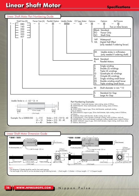
<strong>Linear</strong> <strong>Shaft</strong> <strong>Motor</strong> Part Numbering Guide<br />
Usable Stroke is = L - (L2 * 2) - A<br />
(Support<br />
Length)<br />
A (Forcer Length)<br />
L (<strong>Shaft</strong> Length)<br />
Example: For a S080D-250 L = 310 Stroke = 310 - (10*2) - 40<br />
L2 = 10 Stroke = 310 - 20 - 40<br />
A = 40 Stroke = 250<br />
<strong>Linear</strong> <strong>Shaft</strong> <strong>Motor</strong> Dimension Guide<br />
16<br />
P (Mounting Pitch)<br />
P1<br />
(Mounting Pitch)<br />
Notes:<br />
• The dimension S (Stroke) should be used for limit switch spacing.<br />
• The total length of the shaft (L) can be calculated using the following formula: L (Total Length) = S (Stroke) + A (Forcer Length) + 2 * L2 (Support Length)<br />
www.npmeurope.com<br />
(Support<br />
Length)<br />
(<strong>Shaft</strong> Diameter)<br />
D<br />
D<br />
(<strong>Shaft</strong> Diameter)<br />
Mx (Mounting holes) - 4 Mx (Mounting holes) - 6<br />
Wire Length: 300 mm<br />
D1(Forcer<br />
Bore Diameter)<br />
L2<br />
(Support Length)<br />
A (Forcer Length)<br />
L (<strong>Shaft</strong> Length)<br />
L2<br />
(Support Length)<br />
D<br />
B (Forcer Width)<br />
G (Gap)<br />
B (Forcer Width)<br />
30<br />
10<br />
L2<br />
(Support Length)<br />
P<br />
P<br />
40 (Mounting Pitch) (Mounting Pitch) 40<br />
P1<br />
(Mounting Pitch)<br />
N i p p o n P u l s e<br />
75<br />
Wire Length: 300 mm<br />
A (Forcer Length)<br />
L (<strong>Shaft</strong> Length)<br />
L2<br />
(Support Length)<br />
Specifications<br />
<strong>Shaft</strong> Size (D) Forcer Size (A) Parallel Option Usable Stroke CE Type <strong>Motor</strong> Options Options #of Forcers<br />
S X XX XXXXst CE — XX — XX — XX<br />
— 080<br />
160<br />
200<br />
250<br />
320<br />
427<br />
— — —<br />
—<br />
Blank Standard<br />
FO Forcer O<strong>nl</strong>y<br />
SO <strong>Shaft</strong> O<strong>nl</strong>y<br />
WP Waterproof<br />
HA Digital Hall Effect<br />
(o<strong>nl</strong>y needed if ordering forcer)<br />
Blank Standard<br />
PL Parallel <strong>Motor</strong>s<br />
S Single winding<br />
D Double (2) windings<br />
T Triple (3) windings<br />
Q Quadruple (4) windings<br />
X Octuple (8) windings<br />
SS Single winding small forcer<br />
DS Double winding small forcer<br />
TS Triple winding small forcer<br />
XX <strong>Shaft</strong> diameter in mm *10<br />
S Standard Air Gap<br />
L Large Air Gap<br />
Two or more forcers<br />
XX Usable stroke in millimeters<br />
(o<strong>nl</strong>y needed if ordering shaft)<br />
Part Numbering Examples<br />
1. S160T-200st: 16mm shaft diameter, triple winding, stroke of 200mm<br />
2. S200D-250st-HA: 20mm shaft diameter, double winding, stroke of 250mm,<br />
Hall effects<br />
3. L250Q-1000st: Large air gap, 25mm shaft diameter, quadruple winding,<br />
stroke of 1000mm<br />
4. L320T-2500st-02: Large air gap, 32mm shaft diameter, triple winding, stroke of 2500mm,<br />
two forcers<br />
5. S200D-SO: 20mm shaft diameter, double winding, forcer o<strong>nl</strong>y<br />
6. S120Q-200st-SO: 12mm diameter, quadruple winding, stroke of 200mm, shaft o<strong>nl</strong>y<br />
7. S350QPL-500st: 35mm shaft diameter, quadruple winding, parallel motors, stroke of 500mm<br />
8. L350SS-1500st-03: Large air gap, 35mm shaft diameter, single winding, small forcer, stroke<br />
of 1500mm, three forcers<br />
D<br />
(<strong>Shaft</strong> Diameter)<br />
D<br />
64<br />
D1(Forcer<br />
Bore Diameter)<br />
G (Gap)<br />
82<br />
B (Forcer Width)<br />
B (Forcer Width)