

LM3466 Smart Linear LED Driver for Multi ... - Texas Instruments
LM3466 Smart Linear LED Driver for Multi ... - Texas Instruments
LM3466 Smart Linear LED Driver for Multi ... - Texas Instruments

You also want an ePaper? Increase the reach of your titles
YUMPU automatically turns print PDFs into web optimized ePapers that Google loves.
<strong>LM3466</strong><br />
June 7, 2012<br />
<strong>Smart</strong> <strong>Linear</strong> <strong>LED</strong> <strong>Driver</strong> <strong>for</strong> <strong>Multi</strong>-Channel <strong>LED</strong> Systems<br />
General Description<br />
The <strong>LM3466</strong> integrates a linear <strong>LED</strong> driver <strong>for</strong> lighting systems<br />
which consist of multiple <strong>LED</strong> strings powered by a<br />
constant current power supply. It equalizes the current provided<br />
by the supply in a pre-set ratio <strong>for</strong> each active <strong>LED</strong><br />
string, where an active string is a fully turned on <strong>LED</strong> string,<br />
regardless of the number of strings connected to the supply<br />
or the <strong>for</strong>ward voltage of each <strong>LED</strong> string. If any <strong>LED</strong> string<br />
opens during operation, the <strong>LM3466</strong> automatically equalizes<br />
the supply current through all of the remaining active <strong>LED</strong><br />
strings. As a result, the overall brightness of the lighting system<br />
is maintained even if some <strong>LED</strong> strings open during<br />
operation.<br />
The <strong>LM3466</strong> lighting system is simple to design owing to a<br />
proprietary control scheme. To minimize the component<br />
count, the <strong>LM3466</strong> integrates a 70V, 1.5A N-channel power<br />
MOSFET with a current limit of 2.06A. To add one more <strong>LED</strong><br />
string to the system, only a single resistor, a capacitor, and a<br />
<strong>LM3466</strong> are required. Other supervisory features of the<br />
<strong>LM3466</strong> include under-voltage lock-out, fault reporting, thermal<br />
latch off, and thermal shutdown protection.<br />
The <strong>LM3466</strong> consists of only linear circuitry so that the EMI<br />
of the application circuit is not deteriorated. The <strong>LM3466</strong> lighting<br />
system is EMI friendly if the constant current power supply<br />
used is complied to EMI standards. The <strong>LM3466</strong> is available<br />
in the PSOP-8 exposed DAP and TO220-7 packages.<br />
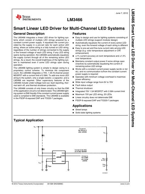
Typical Application<br />
Features<br />
■ Easy to design and use <strong>for</strong> lighting systems consisting of<br />
multiple <strong>LED</strong> strings (support modular design)<br />
■ Automatically equalizes the current of every active <strong>LED</strong><br />
string, even the <strong>for</strong>ward voltage of each string is different<br />
■ Easy to pre-set and fine-tune current ratio among <strong>LED</strong><br />
strings (e.g. color temperature adjustment or CRI<br />
enhancement)<br />
■ ±1% current accuracy at room temperature and ±1.5%<br />
over temperature<br />
■ Maintains constant output power if some strings open<br />
(inactive) by automatically equalizing the current of<br />
remaining active <strong>LED</strong> strings<br />
■ Works with a constant current power supply (ac/dc or dc/<br />
dc), and no communication to/from the constant current<br />
power supply is required<br />
■ Operates with minimum voltage overhead to maximize<br />
power efficiency<br />
■ Wide input voltage range from 6V to 70V<br />
■ Fault status output<br />
■ Thermal shutdown<br />
■ Integrated 70V 1.5A MOSFET with 2.06A current limit<br />
■ Maximum 70V per <strong>LED</strong> string, 20 <strong>LED</strong>s<br />
■ <strong>Linear</strong> circuitry does not deteriorate EMI<br />
■ PSOP-8 exposed DAP and TO220-7 packages<br />
Applications<br />
■ Street lamps<br />
■ Solid state lighting systems<br />
© 2012 <strong>Texas</strong> <strong>Instruments</strong> Incorporated 301589 SNOSB96C www.ti.com<br />
30158901<br />
<strong>LM3466</strong> <strong>Smart</strong> <strong>Linear</strong> <strong>LED</strong> <strong>Driver</strong> <strong>for</strong> <strong>Multi</strong>-Channel <strong>LED</strong> Systems
<strong>LM3466</strong><br />
Connection Diagrams<br />
Top View<br />
ePSOP-8<br />
Ordering In<strong>for</strong>mation<br />
30158902<br />
Top View<br />
TO220-7<br />
Order Number Spec. Package Type NSC Package Drawing Supplied As<br />
<strong>LM3466</strong>MR NOPB ePSOP-8 MRA08A 95 Units in Anti-Static Rails<br />
<strong>LM3466</strong>MRX 2500 units on Tape and Reel<br />
<strong>LM3466</strong>TA NOPB TO220-7 TA07A 45 Units in Anti-Static Rails<br />
Pin Descriptions<br />
Pin Name Description Application In<strong>for</strong>mation<br />
ePSOP-8 TO220-7<br />
1 5 I<strong>LED</strong> Current Regulator Input Connects to the drain of the integrated power MOSFET. Connects this<br />
pin to the cathode of an <strong>LED</strong> string. Connects a capacitor from this pin<br />
to ground to minimize noise if the connecting cable to the <strong>LED</strong> string is<br />
long.<br />
2 6 COMM Open-drain Status Output Indicates the status of the <strong>LM3466</strong> including startup, <strong>LED</strong> string active/<br />
inactive, TSD.<br />
3 7 VIN Input Voltage Supply Connects to voltage supply from 6V to 70V. Connects a 10 nF capacitor<br />
from this pin to ground <strong>for</strong> decoupling.<br />
4 1 VEQ Control Voltage Connects to the VEQ pin of other <strong>LM3466</strong> with a 51Ω resistor in series<br />
with a 1 µF capacitor to ground.<br />
5 4 GND Ground Connects to ground.<br />
6 2 SEN Current Sense Input Senses the voltage of an external current sensing resistor.<br />
7,8 3 SRC Source of Power<br />
MOSFET<br />
30158932<br />
Connects to the source of the integrated power MOSFET. Connects<br />
this pin to an external current sensing resistor.<br />
DAP DAP Exposed Pad Thermal connection pad. Connects to a ground plane.<br />
www.ti.com 2
Absolute Maximum Ratings (Note 1)<br />
If Military/Aerospace specified devices are required,<br />
please contact the <strong>Texas</strong> <strong>Instruments</strong> Sales Office/<br />
Distributors <strong>for</strong> availability and specifications.<br />
VIN, I<strong>LED</strong> to GND -0.3V to 75V<br />
COMM to GND -0.3V to 7V<br />
SEN, SRC, VEQ to GND -0.3V to 5V<br />
ESD Rating (Note 2)<br />
Human Body Model ±2 kV<br />
Storage Temperature Range −65°C to + 150°C<br />
Junction Temperature (T J ) + 150°C<br />
Operating Ratings<br />
Supply Voltage Range (VIN) 6V to 70V<br />
Junction Temperature Range (T J ) −40°C to + 125°C<br />
Thermal Resistance (θ JC )<br />
ePSOP-8 (Note 3) 12.8 °C/W<br />
TO220-7 (Note 4) 2.5 °C/W<br />
Electrical Characteristics Specification with standard type are <strong>for</strong> T A = T J = +25°C only; limits in boldface type<br />
apply over the full Operating Junction Temperature (T J ) range. Minimum and Maximum are guaranteed through test, design or<br />
statistical correlation. Typical values represent the most likely parametric norm at T J = +25°C, and are provided <strong>for</strong> reference<br />
purposes only. Unless otherwise stated, the following conditions apply: V IN = 48V.<br />
Symbol Parameter Conditions Min Typ Max Units<br />
V IN -UVLO-UPPER<br />
VIN pin under-voltage lockout<br />
(UVLO) upper threshold<br />
V IN increasing 4.06 4.78 5.30 V<br />
V IN -UVLO-HYS VIN pin UVLO hysteresis V IN decreasing 0.52 V<br />
I IN Operating current to the VIN pin 550 640 µA<br />
V SEN The SEN pin voltage regulation V EQ = 200 mV 197.1 200 201.0 mV<br />
195.6 200 201.5 mV<br />
I SEN SEN pin bias current out (ePSOP-8) V SEN = 0V 9.77 10.5 11.23 µA<br />
SEN pin bias current out (TO220–7) V SEN = 0V 9.35 10.29 11.23 µA<br />
I <strong>LED</strong>-OFF I<strong>LED</strong> pin off current V I<strong>LED</strong> = 70V 0.1 0.6 µA<br />
R DS(on)<br />
Integrated power MOSFET onresistance<br />
I I<strong>LED</strong> = 300 mA 0.5 1.2 Ω<br />
V SRC-OPEN SRC pin open circuit threshold V SEN = V SRC , V COMM = 0V 25 31 37 mV<br />
I LIMIT Current Limit V SEN = V SRC = 0V, V I<strong>LED</strong> = 3V 1.75 2.06 2.35 A<br />
COMM ILOW COMM pin pull-low current V COMM = 5V 34 54 µA<br />
COMM VHIGH COMM pin pull-high voltage COMM pin to ground through a 10<br />
kΩ<br />
6.0 V<br />
T SD Thermal Shutdown 150 °C<br />
Note 1: Absolute Maximum Ratings are limits beyond which damage to the device may occur. Operating Ratings are conditions under which operation of the<br />
device is intended to be functional. For guaranteed specifications and test conditions, see the Electrical Characteristics.<br />
Note 2: The human body model is a 100 pF capacitor discharged through a 1.5 kΩ resistor into each pin.<br />
Note 3: θ JC measurements are per<strong>for</strong>med in general accordance with Mil-Std 883B, Method 1012.1 and utilize the copper heat sink technique. Copper Heat Sink<br />
@ 18°C with an ambient temperature @ 22°C.<br />
Note 4: θ JC measurements are per<strong>for</strong>med in general accordance with Mil-Std 883B, Method 1012.1 and utilize the copper heat sink technique. Copper Heat Sink<br />
@ 60°C.<br />
3 www.ti.com<br />
<strong>LM3466</strong>
<strong>LM3466</strong><br />
Typical Per<strong>for</strong>mance Characteristics Unless otherwise specified the following conditions apply: T J =<br />
25°C, V IN = 48V with configuration in the additional application circuit <strong>for</strong> I <strong>LED</strong> = 0.35A shown in this datasheet.<br />
I IN (μA)<br />
600<br />
580<br />
560<br />
540<br />
520<br />
500<br />
Quiescent Current, I IN vs V IN<br />
125°C<br />
-40°C<br />
25°C<br />
0 10 20 30 40 50 60 70<br />
V IN (V)<br />
30158926<br />
Current Regulation (Channel to Channel) vs Temperature<br />
R DS(on)(mΩ)<br />
700<br />
650<br />
600<br />
550<br />
500<br />
450<br />
400<br />
R DS(on) vs Tempearture<br />
30158922<br />
-50 0 50 100 150<br />
TEMPERATURE (°C)<br />
30158921<br />
www.ti.com 4<br />
Current Regulation vs V IN<br />
Efficiency vs V IN<br />
Current Regulation vs V <strong>LED</strong><br />
30158904<br />
30158906<br />
30158923
I SEN(μA)<br />
11.0<br />
10.9<br />
10.8<br />
10.7<br />
10.6<br />
10.5<br />
10.4<br />
10.3<br />
10.2<br />
10.1<br />
10.0<br />
Power Up<br />
I SEN vs Temperature<br />
30158909<br />
-50 0 50 100 150<br />
TEMPERATURE (°C)<br />
30158924<br />
CURRENT LIMIT (A)<br />
2.5<br />
2.4<br />
2.3<br />
2.2<br />
2.1<br />
2.0<br />
1.9<br />
1.8<br />
1.7<br />
1.6<br />
<strong>LED</strong> String Disconnect<br />
Current Limit vs Temperature<br />
30158910<br />
1.5<br />
-50 0 50 100 150<br />
TEMPERATURE (°C)<br />
30158925<br />
5 www.ti.com<br />
<strong>LM3466</strong>
<strong>LM3466</strong><br />
Block Diagram<br />
Overview<br />
The <strong>LM3466</strong> integrates a linear <strong>LED</strong> driver <strong>for</strong> lighting systems<br />
which consist of multiple <strong>LED</strong> strings powered by a<br />
constant current power supply. An ideal constant current power<br />
supply delivers a constant current (I S ) regardless of the<br />
output voltage of the connecting load. In the lighting system,<br />
each <strong>LM3466</strong> regulates the current of an <strong>LED</strong> string. The current<br />
I S provided by the supply is equalized (i.e. shared in a<br />
pre-set ratio determined by a single resistor) through each<br />
active <strong>LED</strong> string automatically, regardless of the number of<br />
strings connected to the supply or the <strong>for</strong>ward voltage of each<br />
string. Here, an active <strong>LED</strong> string refers to a fully turned on<br />
<strong>LED</strong> string. If any <strong>LED</strong> string opens during operation, the <strong>LED</strong><br />
current of all remaining active <strong>LED</strong> strings will increase to<br />
equalize the current provided by the supply automatically. As<br />
a result, the total output power remains nearly the same in<br />
case of the decrease of active <strong>LED</strong> strings. This gives an advantage<br />
that the overall brightness of the lighting system is<br />
maintained even if some <strong>LED</strong> strings open during operation.<br />
A <strong>LM3466</strong> lighting system is simple to design owing to a proprietary<br />
control scheme. To minimize the component count,<br />
the <strong>LM3466</strong> integrates a 70V, 1.5A N-channel MOSFET with<br />
a current limit of 2.06A. To add one more <strong>LED</strong> string to the<br />
system, only a single resistor, a capacitor, and an <strong>LM3466</strong><br />
are required. Other supervisory features of the <strong>LM3466</strong> include<br />
under-voltage lock-out, fault reporting, thermal latchoff,<br />
and thermal shutdown protection.<br />
The <strong>LM3466</strong> consists of only linear circuitry so that the EMI<br />
of the application circuit is not deteriorated. The <strong>LM3466</strong> lighting<br />
system is EMI friendly if the constant current power supply<br />
used is complied to EMI standards. The <strong>LM3466</strong> is available<br />
in a PSOP-8 exposed DAP and TO220-7 packages.<br />
www.ti.com 6<br />
Current Regulator<br />
30158929<br />
The <strong>LM3466</strong> integrates a current regulator to control the current<br />
of a connected <strong>LED</strong> string. The current is delivered from<br />
the supply through the <strong>LED</strong> string, the I<strong>LED</strong> pin, the integrated<br />
power MOSFET, the SRC pin, and the sensing resistor<br />
R SEN connecting from the SRC pin to ground (Figure 1). The<br />
voltage of the sensing resistor is fed back to the <strong>LM3466</strong><br />
through the SEN pin, either by direct connection or through<br />
an extra resistor R SL . The <strong>LM3466</strong> regulates the voltage of<br />
the SEN pin (V SEN ) to a voltage set by its control block. If the<br />
sensing resistor of each <strong>LM3466</strong> (R SEN,k , k = 1, 2, …, n) is the<br />
same, the <strong>LED</strong> current of each active <strong>LED</strong> string is the same.<br />
If R SEN,k of any <strong>LM3466</strong> is different from others, the corresponding<br />
<strong>LED</strong> current (I <strong>LED</strong>,k ) is different, while V SEN of each<br />
<strong>LM3466</strong> is still the same as others. The <strong>LED</strong> current of string<br />
k is<br />
where I S is the current of the supply, and<br />
In addition to determining the <strong>LED</strong> current by means of<br />
R SEN,k , an external resistor R SL,k connecting between the SEN<br />
pin and R SEN,k can be used to fine tune the <strong>LED</strong> current <strong>for</strong><br />
the purpose of color temperature adjustment or CRI enhancement.<br />
The SEN pin sources a constant bias current of 10.29<br />
µA such that a constant voltage drop on R SL,k reduces the<br />
<strong>LED</strong> current. Using an external resistor R SL,k affects the current<br />
of other <strong>LED</strong> strings. If R SL,k is added in the k-th <strong>LM3466</strong>,<br />
the corresponding <strong>LED</strong> current is
and the <strong>LED</strong> current of other strings is<br />
FIGURE 2. Variation of I <strong>LED</strong> vs R SL,k<br />
<strong>LED</strong> String Disconnect and<br />
Reconnect<br />
FIGURE 1. A Single <strong>LM3466</strong> within a Lighting System<br />
30158916<br />
One major advantage of the <strong>LM3466</strong> lighting system is that<br />
the overall brightness can be maintained even if some <strong>LED</strong><br />
strings open during operation. If an active <strong>LED</strong> string is suddenly<br />
disconnected, the <strong>LM3466</strong> will automatically equalize<br />
the current delivered by the supply I S (i.e. each string increases<br />
its <strong>LED</strong> current in this case) so as to keep I S constant.<br />
However, the equalization takes place only after the <strong>LED</strong><br />
string is confirmed inactive. Once the string is disconnected,<br />
V EQ will go to a cycle (goes up and down). If the string is still<br />
disconnected <strong>for</strong> a period of 253 consecutive cycles, the<br />
where i = 1, 2, …, n except k. The <strong>LED</strong> current of <strong>LED</strong> string<br />
k is reduced, while the <strong>LED</strong> current of other channels increases.<br />
Figure 2 shows a typical example that the variation of <strong>LED</strong><br />
current on varying R SL,k .<br />
30158915<br />
string is confirmed inactive. Consequently, the current of other<br />
<strong>LED</strong> strings increases to equalize I S . The output power and<br />
the overall brightness of the lighting system can be maintained.<br />
If a new <strong>LED</strong> string connects to the system, such as if the<br />
disconnected <strong>LED</strong> string is reconnected again, a power reset<br />
is recommended to ensure proper operation. The <strong>for</strong>ward<br />
voltage of the new <strong>LED</strong> string may be higher than the instantaneous<br />
V IN , which corresponds to the <strong>for</strong>ward voltage of the<br />
highest active <strong>LED</strong> string. A power reset ensures that V IN<br />
goes to the peak voltage (a default characteristic of a constant<br />
current power supply) in order to start up the <strong>LED</strong> string with<br />
the highest <strong>for</strong>ward voltage.<br />
Communication Pin<br />
The COMM pin serves as a communication link among all<br />
<strong>LM3466</strong> in the lighting system. It also indicates the status of<br />
the device. The COMM pin is pulled low at startup. After startup,<br />
the COMM pin is high/low to indicate that the corresponding<br />
<strong>LED</strong> string is active/inactive.<br />
For proper operation of a <strong>LM3466</strong> system, the COMM pin of<br />
all <strong>LM3466</strong> should be either shorted together or connected<br />
through a diode in parallel with a resistor. Figure 3 shows an<br />
optional circuit <strong>for</strong> the COMM pin to indicate whether each<br />
<strong>LED</strong> string is active by means of small signal <strong>LED</strong>s. The<br />
COMM pin of each <strong>LM3466</strong> is connected to an external test<br />
point COMM_ALL through the optional circuit.<br />
The COMM pin is low if the <strong>LM3466</strong> is under thermal protection.<br />
7 www.ti.com<br />
<strong>LM3466</strong>
<strong>LM3466</strong><br />
30158917<br />
FIGURE 3. Optional Circuit <strong>for</strong> the COMM Pin<br />
High Voltage Application<br />
For any application with the <strong>for</strong>ward voltage of an <strong>LED</strong> string<br />
higher than 70V, which is the maximum operating voltage of<br />
the <strong>LM3466</strong>, an external MOSFET circuit as shown in Figure<br />
4 is recommended <strong>for</strong> each channel in order to protect the<br />
I<strong>LED</strong> pin from damaging by a high voltage owing to shorting<br />
<strong>LED</strong>s (or even the whole <strong>LED</strong> string). To avoid the I<strong>LED</strong> pin<br />
damage from a high voltage generated by the leakage current,<br />
a resistor R <strong>LED</strong> (1 MΩ is suggested) is placed between<br />
the I<strong>LED</strong> pin and ground. In addition, since V <strong>LED</strong> is higher than<br />
70V in this case, the VIN pin cannot be directly connected to<br />
V <strong>LED</strong> . External power supplies <strong>for</strong> V IN and V G (to drive the external<br />
MOSFET) are required. Alternatively, Figure 5 shows<br />
a circuit <strong>for</strong> supplying V IN and V G (<strong>for</strong> all channels in the system).<br />
30158927<br />
FIGURE 4. External MOSFET circuit <strong>for</strong> high voltage applications<br />
30158928<br />
FIGURE 5. Power supply circuit <strong>for</strong> the external MOSFET<br />
circuit<br />
www.ti.com 8<br />
Thermal Protection<br />
Thermal protection is implemented by an internal thermal<br />
shutdown circuit which activates at 150°C (typically) to disable<br />
the <strong>LM3466</strong>. In this case, the integrated power MOSFET<br />
turns off and the COMM pin is pulled low. Thermal protection<br />
helps prevent catastrophic failures from accidental device<br />
overheating. When the junction temperature of the <strong>LM3466</strong><br />
falls back below 140°C (typical hysteresis = 10°C), the<br />
<strong>LM3466</strong> resumes normal operation.
Thermal Latch Off and Derating<br />
If thermal protection cycles <strong>for</strong> 253 times consecutively, the<br />
<strong>LM3466</strong> is latched off until power reset.<br />
Thermal derating is required <strong>for</strong> only the ePSOP-8 package<br />
(but not the TO220–7 package). When fully turned on, the<br />
integrated power MOSFET of the <strong>LM3466</strong> is capable of conducting<br />
a current of 1.5A below an ambient temperature of<br />
100°C. At 125°C, the <strong>LM3466</strong> can conduct a current of 1A<br />
without thermal shutdown with a PCB ground plane copper<br />
area of 60cm 2, 2 oz/Cu. Figure 6 shows a thermal derating<br />
curve <strong>for</strong> the minimum conducting current of a fully turned on<br />
<strong>LM3466</strong> integrated power MOSFET without thermal shutdown<br />
against an ambient temperature up to 125°C.<br />
I<strong>LED</strong> CURRENT (A)<br />
1.6<br />
1.5<br />
1.4<br />
1.3<br />
1.2<br />
1.1<br />
1.0<br />
0 25 50 75 100 125<br />
AMBIENT TEMPERATURE (°C)<br />
30158920<br />
FIGURE 6. Thermal Derating Curve <strong>for</strong> the ePSOP-8<br />
Package<br />
Application In<strong>for</strong>mation<br />
Consider a <strong>LM3466</strong> lighting system which is powered by a<br />
1.75A constant current power supply and consists of 5 <strong>LED</strong><br />
strings with 14 <strong>LED</strong>s per string. It is designed that the <strong>LED</strong><br />
current of every <strong>LED</strong> string is 0.35A.<br />
EXTERNAL COMPONENTS<br />
R SEN : To set the <strong>LED</strong> current of all 5 <strong>LED</strong> strings equal, the<br />
sensing resistors corresponding to all 5 <strong>LM3466</strong> are equal. It<br />
is recommended that the nominal voltage of the SEN pin<br />
V SEN should be around 0.3V. There<strong>for</strong>e, R SEN is selected to<br />
be 1Ω. As a result, V SEN should be 0.35V if the <strong>LED</strong> current<br />
is 0.35A.<br />
C <strong>LED</strong> : If the cable connecting the <strong>LED</strong> string is long, the parasitic<br />
inductance of the cable may generate noise. If this<br />
happens, a high quality ceramic capacitor should be connected<br />
between the I<strong>LED</strong> pin and ground. In this example, a 100V,<br />
1 µF ceramic capacitor is used.<br />
C IN : A high quality ceramic capacitor <strong>for</strong> decoupling should be<br />
connected from the VIN pin to ground. In this example, a<br />
100V, 0.01 µF ceramic capacitor is used.<br />
R EQ and C EQ : The VEQ pins of all <strong>LM3466</strong> are shorted together<br />
and then connected to ground through R EQ and C EQ .<br />
Only one R EQ and one C EQ are required <strong>for</strong> each <strong>LM3466</strong><br />
lighting system. It is recommended that R EQ be 51.1Ω and<br />
C EQ be 1 µF.<br />
PC BOARD LAYOUT<br />
To minimize the effect of noise, the ground connections of the<br />
<strong>LM3466</strong> and the sense resistor R SEN,k should be closed.<br />
Good heat dissipation helps optimize the per<strong>for</strong>mance of the<br />
<strong>LM3466</strong>. The ground plane should be used to connect the<br />
exposed pad of the <strong>LM3466</strong>, which is internally connected to<br />
the <strong>LM3466</strong> die substrate. The area of the ground plane<br />
should be extended as much as possible on the same copper<br />
layer above and below the <strong>LM3466</strong>. Using numerous vias<br />
beneath the exposed pad to dissipate heat of the <strong>LM3466</strong> to<br />
another copper layer is also a good practice.<br />
9 www.ti.com<br />
<strong>LM3466</strong>
<strong>LM3466</strong><br />
Additional Application Circuit<br />
www.ti.com 10<br />
30158918<br />
FIGURE 7. Application Circuit of a <strong>LM3466</strong> Lighting System
Physical Dimensions inches (millimeters) unless otherwise noted<br />
8-Lead Plastic ePSOP Package<br />
NS Package Number MRA08A<br />
7-Lead TO220-7 Package<br />
NS Package Number TA07A<br />
11 www.ti.com<br />
<strong>LM3466</strong>
<strong>LM3466</strong> <strong>Smart</strong> <strong>Linear</strong> <strong>LED</strong> <strong>Driver</strong> <strong>for</strong> <strong>Multi</strong>-Channel <strong>LED</strong> Systems<br />
www.ti.com<br />
Notes