Potential Induced Degradation Of solar Cells And panels - Solon
Potential Induced Degradation Of solar Cells And panels - Solon
Potential Induced Degradation Of solar Cells And panels - Solon

Create successful ePaper yourself
Turn your PDF publications into a flip-book with our unique Google optimized e-Paper software.
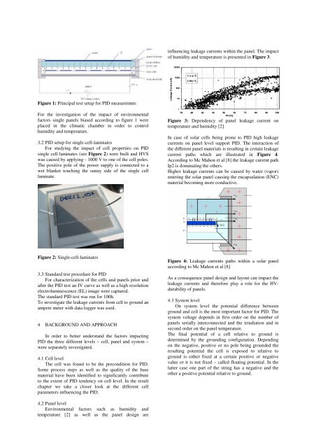
Figure 1: Principal test setup for PID measuremnts<br />
For the investigation of the impact of environmental<br />
factors single <strong>panels</strong> biased according to figure 1 were<br />
placed in the climatic chamber in order to control<br />
humidity and temperature.<br />
3.2 PID setup for single-cell-laminates<br />
For studying the impact of cell properties on PID<br />
single cell laminates (see Figure 2) were built and HVS<br />
was caused by applying - 1000 V to one of the cell poles.<br />
The positive pole of the power supply is connected to a<br />
wet blanket touching the sunny side of the single cell<br />
laminate.<br />
Figure 2: Single-cell-laminates<br />
3.3 Standard test procedure for PID<br />
For characterization of the cells and <strong>panels</strong> prior and<br />
after the PID test an IV curve as well as a high resolution<br />
electroluminescence (EL) image were captured.<br />
The standard PID test was run for 100h.<br />
To investigate the leakage currents from cell to ground an<br />
ampere meter with data logger was used.<br />
4 BACKGROUND AND APPROACH<br />
In order to better understand the factors impacting<br />
PID the three different levels – cell, panel and system –<br />
were separately investigated.<br />
4.1 Cell level<br />
The cell was found to be the precondition for PID.<br />
Some process steps as well as the quality of the base<br />
material have been identified to significantly contribute<br />
to the extent of PID tendency on cell level. In the result<br />
chapter we take a closer look at the different cell<br />
parameters influencing the PID.<br />
4.2 Panel level<br />
Environmental factors such as humidity and<br />
temperature [2] as well as the panel design are<br />
influencing leakage currents within the panel. The impact<br />
of humidity and temperature is presented in Figure 3.<br />
Figure 3: Dependency of panel leakage current on<br />
temperature and humidity [2]<br />
In case of <strong>solar</strong> cells being prone to PID high leakage<br />
currents on panel level support PID. The interaction of<br />
the different panel materials is resulting in certain leakage<br />
current paths which are illustrated in Figure 4.<br />
According to Mc Mahon et al [8] the leakage current path<br />
Ip2 is dominating the others.<br />
Higher leakage currents can be caused by water (vapor)<br />
entering the <strong>solar</strong> panel causing the encapsulation (ENC)<br />
material becoming more conductive.<br />
Figure 4: Leakage currents paths within a <strong>solar</strong> panel<br />
according to Mc Mahon et al [8]<br />
As a consequence panel design and layout can impact the<br />
leakage currents and therefore play a role for the HVdurability<br />
of <strong>panels</strong>.<br />
4.3 System level<br />
On system level the potential difference between<br />
ground and cell is the most important factor for PID. The<br />
system voltage depends in first order on the number of<br />
<strong>panels</strong> serially interconnected and the irradiation and in<br />
second order on the panel temperature.<br />
The final potential of a cell relative to ground is<br />
determined by the grounding configuration. Depending<br />
on the negative, positive or no pole being grounded the<br />
resulting potential the cell is exposed to relative to<br />
ground is either fixed at a certain positive or negative<br />
value or it is not fixed – called floating potential. In the<br />
latter case one part of the string has a negative and the<br />
other a positive potential relative to ground.