Potential Induced Degradation Of solar Cells And panels - Solon
Potential Induced Degradation Of solar Cells And panels - Solon
Potential Induced Degradation Of solar Cells And panels - Solon

Create successful ePaper yourself
Turn your PDF publications into a flip-book with our unique Google optimized e-Paper software.
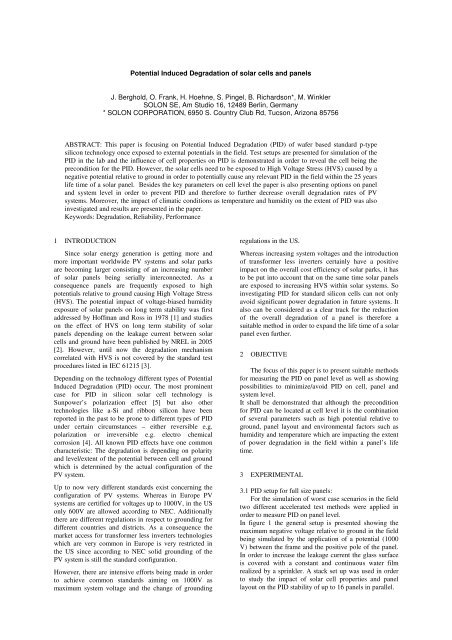
<strong>Potential</strong> <strong>Induced</strong> <strong>Degradation</strong> of <strong>solar</strong> cells and <strong>panels</strong><br />
J. Berghold, O. Frank, H. Hoehne, S. Pingel, B. Richardson*, M. Winkler<br />
SOLON SE, Am Studio 16, 12489 Berlin, Germany<br />
* SOLON CORPORATION, 6950 S. Country Club Rd, Tucson, Arizona 85756<br />
ABSTRACT: This paper is focusing on <strong>Potential</strong> <strong>Induced</strong> <strong>Degradation</strong> (PID) of wafer based standard p-type<br />
silicon technology once exposed to external potentials in the field. Test setups are presented for simulation of the<br />
PID in the lab and the influence of cell properties on PID is demonstrated in order to reveal the cell being the<br />
precondition for the PID. However, the <strong>solar</strong> cells need to be exposed to High Voltage Stress (HVS) caused by a<br />
negative potential relative to ground in order to potentially cause any relevant PID in the field within the 25 years<br />
life time of a <strong>solar</strong> panel. Besides the key parameters on cell level the paper is also presenting options on panel<br />
and system level in order to prevent PID and therefore to further decrease overall degradation rates of PV<br />
systems. Moreover, the impact of climatic conditions as temperature and humidity on the extent of PID was also<br />
investigated and results are presented in the paper.<br />
Keywords: <strong>Degradation</strong>, Reliability, Performance<br />
1 INTRODUCTION<br />
Since <strong>solar</strong> energy generation is getting more and<br />
more important worldwide PV systems and <strong>solar</strong> parks<br />
are becoming larger consisting of an increasing number<br />
of <strong>solar</strong> <strong>panels</strong> being serially interconnected. As a<br />
consequence <strong>panels</strong> are frequently exposed to high<br />
potentials relative to ground causing High Voltage Stress<br />
(HVS). The potential impact of voltage-biased humidity<br />
exposure of <strong>solar</strong> <strong>panels</strong> on long term stability was first<br />
addressed by Hoffman and Ross in 1978 [1] and studies<br />
on the effect of HVS on long term stability of <strong>solar</strong><br />
<strong>panels</strong> depending on the leakage current between <strong>solar</strong><br />
cells and ground have been published by NREL in 2005<br />
[2]. However, until now the degradation mechanism<br />
correlated with HVS is not covered by the standard test<br />
procedures listed in IEC 61215 [3].<br />
Depending on the technology different types of <strong>Potential</strong><br />
<strong>Induced</strong> <strong>Degradation</strong> (PID) occur. The most prominent<br />
case for PID in silicon <strong>solar</strong> cell technology is<br />
Sunpower’s polarization effect [5] but also other<br />
technologies like a-Si and ribbon silicon have been<br />
reported in the past to be prone to different types of PID<br />
under certain circumstances – either reversible e.g.<br />
polarization or irreversible e.g. electro chemical<br />
corrosion [4]. All known PID effects have one common<br />
characteristic: The degradation is depending on polarity<br />
and level/extent of the potential between cell and ground<br />
which is determined by the actual configuration of the<br />
PV system.<br />
Up to now very different standards exist concerning the<br />
configuration of PV systems. Whereas in Europe PV<br />
systems are certified for voltages up to 1000V, in the US<br />
only 600V are allowed according to NEC. Additionally<br />
there are different regulations in respect to grounding for<br />
different countries and districts. As a consequence the<br />
market access for transformer less inverters technologies<br />
which are very common in Europe is very restricted in<br />
the US since according to NEC solid grounding of the<br />
PV system is still the standard configuration.<br />
However, there are intensive efforts being made in order<br />
to achieve common standards aiming on 1000V as<br />
maximum system voltage and the change of grounding<br />
regulations in the US.<br />
Whereas increasing system voltages and the introduction<br />
of transformer less inverters certainly have a positive<br />
impact on the overall cost efficiency of <strong>solar</strong> parks, it has<br />
to be put into account that on the same time <strong>solar</strong> <strong>panels</strong><br />
are exposed to increasing HVS within <strong>solar</strong> systems. So<br />
investigating PID for standard silicon cells can not only<br />
avoid significant power degradation in future systems. It<br />
also can be considered as a clear track for the reduction<br />
of the overall degradation of a panel is therefore a<br />
suitable method in order to expand the life time of a <strong>solar</strong><br />
panel even further.<br />
2 OBJECTIVE<br />
The focus of this paper is to present suitable methods<br />
for measuring the PID on panel level as well as showing<br />
possibilities to minimize/avoid PID on cell, panel and<br />
system level.<br />
It shall be demonstrated that although the precondition<br />
for PID can be located at cell level it is the combination<br />
of several parameters such as high potential relative to<br />
ground, panel layout and environmental factors such as<br />
humidity and temperature which are impacting the extent<br />
of power degradation in the field within a panel’s life<br />
time.<br />
3 EXPERIMENTAL<br />
3.1 PID setup for full size <strong>panels</strong>:<br />
For the simulation of worst case scenarios in the field<br />
two different accelerated test methods were applied in<br />
order to measure PID on panel level.<br />
In figure 1 the general setup is presented showing the<br />
maximum negative voltage relative to ground in the field<br />
being simulated by the application of a potential (1000<br />
V) between the frame and the positive pole of the panel.<br />
In order to increase the leakage current the glass surface<br />
is covered with a constant and continuous water film<br />
realized by a sprinkler. A stack set up was used in order<br />
to study the impact of <strong>solar</strong> cell properties and panel<br />
layout on the PID stability of up to 16 <strong>panels</strong> in parallel.
Figure 1: Principal test setup for PID measuremnts<br />
For the investigation of the impact of environmental<br />
factors single <strong>panels</strong> biased according to figure 1 were<br />
placed in the climatic chamber in order to control<br />
humidity and temperature.<br />
3.2 PID setup for single-cell-laminates<br />
For studying the impact of cell properties on PID<br />
single cell laminates (see Figure 2) were built and HVS<br />
was caused by applying - 1000 V to one of the cell poles.<br />
The positive pole of the power supply is connected to a<br />
wet blanket touching the sunny side of the single cell<br />
laminate.<br />
Figure 2: Single-cell-laminates<br />
3.3 Standard test procedure for PID<br />
For characterization of the cells and <strong>panels</strong> prior and<br />
after the PID test an IV curve as well as a high resolution<br />
electroluminescence (EL) image were captured.<br />
The standard PID test was run for 100h.<br />
To investigate the leakage currents from cell to ground an<br />
ampere meter with data logger was used.<br />
4 BACKGROUND AND APPROACH<br />
In order to better understand the factors impacting<br />
PID the three different levels – cell, panel and system –<br />
were separately investigated.<br />
4.1 Cell level<br />
The cell was found to be the precondition for PID.<br />
Some process steps as well as the quality of the base<br />
material have been identified to significantly contribute<br />
to the extent of PID tendency on cell level. In the result<br />
chapter we take a closer look at the different cell<br />
parameters influencing the PID.<br />
4.2 Panel level<br />
Environmental factors such as humidity and<br />
temperature [2] as well as the panel design are<br />
influencing leakage currents within the panel. The impact<br />
of humidity and temperature is presented in Figure 3.<br />
Figure 3: Dependency of panel leakage current on<br />
temperature and humidity [2]<br />
In case of <strong>solar</strong> cells being prone to PID high leakage<br />
currents on panel level support PID. The interaction of<br />
the different panel materials is resulting in certain leakage<br />
current paths which are illustrated in Figure 4.<br />
According to Mc Mahon et al [8] the leakage current path<br />
Ip2 is dominating the others.<br />
Higher leakage currents can be caused by water (vapor)<br />
entering the <strong>solar</strong> panel causing the encapsulation (ENC)<br />
material becoming more conductive.<br />
Figure 4: Leakage currents paths within a <strong>solar</strong> panel<br />
according to Mc Mahon et al [8]<br />
As a consequence panel design and layout can impact the<br />
leakage currents and therefore play a role for the HVdurability<br />
of <strong>panels</strong>.<br />
4.3 System level<br />
On system level the potential difference between<br />
ground and cell is the most important factor for PID. The<br />
system voltage depends in first order on the number of<br />
<strong>panels</strong> serially interconnected and the irradiation and in<br />
second order on the panel temperature.<br />
The final potential of a cell relative to ground is<br />
determined by the grounding configuration. Depending<br />
on the negative, positive or no pole being grounded the<br />
resulting potential the cell is exposed to relative to<br />
ground is either fixed at a certain positive or negative<br />
value or it is not fixed – called floating potential. In the<br />
latter case one part of the string has a negative and the<br />
other a positive potential relative to ground.
potential [V]<br />
1000<br />
800<br />
600<br />
400<br />
200<br />
0<br />
0<br />
-200<br />
5 10 15 20<br />
-400<br />
-600<br />
-800<br />
-1000<br />
Floating<br />
PV- grd<br />
PV+ grd<br />
panel position in string<br />
Figure 5: <strong>Potential</strong> in a string, different grounding<br />
schemes PV+/PV- and no grounding (floating potential)<br />
5 RESULTS<br />
5.1 Cell level<br />
The following two graphs show the evolution of the<br />
IV curve for a <strong>solar</strong> cell prone to PID and the<br />
corresponding power degradation over time.<br />
Figure 6: Evolution of the IV curve and the<br />
corresponding power with progressing PID<br />
As illustrated in<br />
Table 1 in case of PID shunt resistance as well as the<br />
reverse bias current are affected first followed by FF.<br />
Finally the open circuit voltage decreases reflecting the<br />
junction to be less capable of separating holes and<br />
electrons.<br />
t Uoc Isc P FF<br />
I<br />
(-12V) Rsh<br />
[hr] [V] [A] [W] % [A] [Ω]<br />
0 0,615 8,240 3,61 71,4 0,21 80,4<br />
20 0,619 8,261 3,66 71,5 0,22 80,4<br />
40 0,615 8,258 3,62 71,3 0,30 51,1<br />
80 0,600 8,109 2,65 54,6 >10 0,5<br />
100 0,572 7,882 1,74 38,7 >10 0,2<br />
rel.<br />
PID -7% -4% -52% -46% -<br />
Table 1: Cell IV key parameter change by PID<br />
-<br />
100%<br />
The Isc is the parameter that is least affected but with<br />
advancing PID Isc also degrades. Depending on the<br />
degree of PID the junction is loosing its blocking<br />
characteristic under reverse bias eventually being short<br />
cutted (ohmic shunt). This phenomenon can be visualized<br />
by EL images taken during a PID test shown in the upper<br />
row of Figure 7. After 40hr local shunts appear along the<br />
edge of the cell that degrade further from diode to ohmic<br />
behavior, as can be seen in the reverse bias image in the<br />
lower row of Figure 7. First shunted areas appear bright<br />
but after further PID evolution these areas do not emit<br />
any more breakdown light [6]. Finally after 100hr both<br />
images are dark because of dominating ohmic shunts.<br />
Figure 7: EL image of a cell during PID test (upper row)<br />
and the corresponding reverse bias (-12V) image (lower<br />
row)<br />
The leakage current within the panel is resulting in a<br />
certain charge concentration above the <strong>solar</strong> cell in the<br />
ENC. Depending on certain cell properties these charges<br />
might interact with the emitter and the depletion layer<br />
finally causing shunting of the cell. From semiconductor<br />
industry similar effects are known as (time dependent)<br />
dielectric breakdown or surface inversion [5]. The<br />
electric field of these charge carriers is influencing the pn-junction<br />
in that way that the junction gets more<br />
conductive and the local shunt resistance drops.<br />
There are numerous factors on cell level being important<br />
in respect to PID. In the following we present the<br />
parameters identified to have the most significant impact.<br />
5.1.1 Anti-reflective coating<br />
There are different parameters having an large impact<br />
on PID but the ARC deposition was shown to have a<br />
crucial role in not only influencing but actually<br />
preventing PID on cell level.<br />
In case of typical standard cells ARC is realized by SiNx<br />
applied by a various deposition technologies resulting in<br />
a certain thickness layer thickness and refractive index<br />
(RI) determining the specific properties of the layer.<br />
Figure 8 is illustrating the huge impact of parameter<br />
variations for the ARC deposition on the extent on PID.<br />
It also shows that by using suitable combination of RI<br />
and thickness PID can be completely prevented on cell<br />
level.
Figure 8: Dependency of PID on SiN RI and thickness.<br />
For ARC deposition the third parameter having an impact<br />
on PID was found to be the homogeneity of the resulting<br />
SiN layer which was recognized to be clearly different for<br />
various SiN deposition methods.<br />
The observations made for the role of the SiN parameter<br />
concerning PID can be explained by the different<br />
conductivity of the resulting layer for different parameter<br />
settings making trapping of charges more or less likely.<br />
5.1.2 Wafer material<br />
Also the wafer material has been identified to be<br />
another crucial factor regarding PID. The most<br />
significant parameter in this respect is the base resistivity.<br />
As presented in Figure 9 an increasing base resistivity is<br />
resulting in decreasing PID. Higher base resistivity<br />
representing lower base doping leads to a wider depletion<br />
layer at the junction when the emitter doping is held<br />
constant. Accordingly shunting of the junction is less<br />
likely.<br />
Figure 9: Dependency of PID on base resistivity<br />
Within different experiments with cell suppliers where<br />
cells have been produced at constant cell processing<br />
parameters utilizing different wafer suppliers a significant<br />
batch dependence has been found. This could hint on<br />
systematic variation of certain wafer properties relevant<br />
for PID.<br />
Lower quality silicon or comparably high concentration<br />
of crystal defects seem to increase the tendency of PID<br />
but results have to be further verified.<br />
5.1.3 Emitter<br />
Since the emitter process clearly influences the width<br />
of the depletion layer it can definitely be influencing the<br />
probability for shunting the PN-junction and therefore<br />
the tendency for PID. As it can be seen in Figure 10 with<br />
increasing emitter sheet resistivity PID is also increasing.<br />
Figure 10: Dependency of PID on emitter sheet<br />
resistance.<br />
Beside the trend in <strong>solar</strong> industry to increase the emitter<br />
sheet resistivity for <strong>solar</strong> cells it can be additionally<br />
increased by new process steps such as emitter back<br />
etching or the introduction of the selective emitter<br />
process.<br />
This example shows that process variations within the<br />
cell process which are thought to be of no relevance for<br />
the later application can lead to degradation when the cell<br />
are exposed to an external potential later in the field.<br />
Since there are many factors on cell level impacting PID<br />
there is no easy distinction between cells more or less<br />
prone to PID just by IV characterization. However, due<br />
to the PID mechanism and the impacting factors<br />
discussed above there are some IV characteristics that<br />
hint on lower PID sensitivity: high shunt resistance and<br />
low reverse bias current. Both parameters are depending<br />
on local defects and base resistivity.<br />
According to our recent results the most effective path for<br />
prevention of PID on cell level is the selection of suitable<br />
parameters (RI and thickness) for ARC deposition.<br />
5.2 Panel level<br />
Since PID is not yet completely excluded on cell<br />
level for all industrial <strong>solar</strong> cells being produced today it<br />
is certainly worthwhile to take a closer look on the<br />
possibilities to minimize or exclude PID on the panel<br />
level even in case of <strong>solar</strong> cells prone to PID. In Figure<br />
11 there are shown EL images for a <strong>solar</strong> panel before<br />
and after the PID test (1000V, 100hr).<br />
According to the image after the test some cells degrade<br />
strongly - finally being short circuited - while others<br />
appear to be stable. Being the cell the origin for PID this<br />
observation can be explained by variation of certain cell<br />
properties relevant for PID as discussed in the chapter<br />
above.
Figure 11: EL image of a panel before (upper) and after<br />
(lower) 100hr 1000V PID test<br />
The findings in the EL images do match the observed<br />
power drop of about 30% found after the PID test.<br />
The objective was to investigate how PID on panel level<br />
can be influenced by the panel layout or design. Different<br />
material combinations have been checked in respect to<br />
whether or not the PID is rather supported or suppressed.<br />
It turned out that an important factor is the type of ENC<br />
material since the leakage current can be influenced. In<br />
the following figure the leakage current is shown as a<br />
function of time during a temperature ramp up from -<br />
20°C to 48°C in a humid atmosphere (50% RH).<br />
According to Figure 12 two different encapsulation<br />
materials are causing the peak leakage current to differ by<br />
more than one order of magnitude. The panel can be<br />
described here as a capacitor being charged while the<br />
temperature is rising. When finally the full capacity is<br />
reached the current will drop again.<br />
Figure 12: Leakage current for two <strong>panels</strong> with different<br />
ENC materials during a temperature ramp from -20°C to<br />
48°C with 1000V applied voltage (RH 50%).<br />
As a consequence of this significant difference in leakage<br />
current the PID results with varying ENC materials differ<br />
strongly as shown in Figure 13.<br />
relative PID in %<br />
100,0<br />
80,0<br />
60,0<br />
40,0<br />
20,0<br />
0,0<br />
Material A Material B Material C<br />
Figure 13: PID comparison of three different ENC<br />
materials in <strong>panels</strong> with prone <strong>solar</strong> cells<br />
Since leakage current on panel level seems to be the key<br />
feature for suppressing PID on panel level it was also<br />
investigated how it is influenced by different<br />
environmental factors such as temperature and moisture.<br />
In the Arrhenius plot in Figure 14 it can be seen both<br />
increasing temperature (T-ramp from -20 °C to 85°C) and<br />
increasing humidity (0% versus 50%) resulting in higher<br />
leakage currents.<br />
Figure 14: Arrhenius plot for the leakage current<br />
depending on temperature and humidity during PID test<br />
(1000V, 100h).<br />
The leakage current for the two test <strong>panels</strong> in this test<br />
being exposed to different levels of relative humidity<br />
(RH) also corresponds to the different extent of power<br />
degradation (Table 2) obtained for different RH.<br />
Material<br />
combination<br />
Conditions P in%<br />
Material x T= 85°C; RH=0% - 10<br />
Material x T= 85°C; RH=50% - 32<br />
Material x T= 85°C; RH=100% - 99<br />
Table 2: Power drop of three <strong>panels</strong> (same layout) after<br />
PID test (1000V, 100h, in climatic chamber running a T<br />
ramp -20°C to 85°C) being exposed to different RH.<br />
Even if temperatures and humidity according to Table 2<br />
are meant to be a worst case scenario they show very<br />
impressively the potential impact of environmental
factors on PID.<br />
In order to minimize or avoid PID on panel level and<br />
therefore to increase life time and reliability suitable<br />
material combinations and panel design have to be found<br />
to ensure low leakage currents. In this case PID can be<br />
successfully suppressed even for <strong>panels</strong> with <strong>solar</strong> cells<br />
prone to PID.<br />
Using PID suppressing encapsulation materials is one of<br />
the layout options in this matter. There are alternative<br />
materials to standard EVA better performing in respect to<br />
PID but other criteria like price, handling, long term<br />
stability issues and availability have to be taken into<br />
account.<br />
5.3 System level<br />
As already mentioned one precondition for PID is the<br />
existence of HVS which is very much influenced by the<br />
specific system configuration – mainly by the kind of<br />
grounding. As already shown in Figure 5 the kind of<br />
grounding determines the potential relative to ground a<br />
panel is exposed to which is also changing with panel<br />
position within a string.<br />
In absence of grounding resulting in a so called floating<br />
potential there is only one part of the string being<br />
exposed to a negative potential causing HVS potentially<br />
turning into PID.<br />
The higher the negative potential the panel is exposed to<br />
the higher the extent of PID as illustrated by<br />
corresponding EL images of a string within a floating<br />
system in Figure 15.<br />
PV- PV+<br />
Figure 15: EL image of a PID affected string of a<br />
floating test system. Only the <strong>panels</strong> marked by the red<br />
arrow are exposed to a negative potential relative to<br />
ground and therefore prone to PID.<br />
Therefore avoiding negative potential relative to ground<br />
is one way for p-type standard cells on system level in<br />
order to minimize PID independent on cell and panel<br />
properties. This could be achieved by grounding the<br />
negative pole of the system. However, this is not always<br />
possible since in the last few years inverter technologies<br />
have been widely introduced particularly in Europe<br />
which do not allow the grounding of the negative pole<br />
due to the absence of transformers.<br />
Nevertheless, it could be shown that PID cannot only be<br />
prevented on system level by avoiding negative potential<br />
it could also been shown that PID can even be recovered<br />
by reversing the potential having caused the PID. By<br />
showing the reversibility of the PID effect (provided<br />
electrochemical corrosion is excluded) recovery methods<br />
could be developed for affected <strong>panels</strong> as well as systems<br />
in order to reverse the power loss caused by PID.<br />
The reversibility of PID for <strong>solar</strong> <strong>panels</strong> has been<br />
demonstrated in the lab on PID affected <strong>panels</strong> by<br />
applying the reverse potential in respect to the one<br />
originally causing PID. Whereas for standard like <strong>solar</strong><br />
<strong>panels</strong> the recovery has been done by applying a positive<br />
potential as shown in Figure 16, for other technologies<br />
like Sunpower’s back contact technology it was already<br />
found in 2005 that the polarization effect [4] can be<br />
reversed by applying a negative potential.<br />
Figure 16: <strong>Degradation</strong> and recovery of <strong>panels</strong> in the lab<br />
by reversing the applied potential<br />
As a consequence grounding of the positive pole of the<br />
PV system or even a potential shift towards positive<br />
potential as illustrated in Figure 17 can not only prevent<br />
PID on system level it also supports the regeneration of<br />
the <strong>panels</strong> which is demonstrated in Figure 18.<br />
Figure 17: System configurations supporting the<br />
recovery of PID (solid ground or potential shift) versus<br />
floating potential.<br />
Figure 18: Regeneration of a test string with PID<br />
affected <strong>panels</strong> by solid grounding of the negative pole<br />
The time necessary for the recovery process depends not<br />
only on the potential but – analog to the degradation<br />
process - also on environmental factors such as humidity<br />
and temperature.
6 SUMMARY AND CONCLUSION<br />
This paper addressed a degradation mechanism called<br />
<strong>Potential</strong> <strong>Induced</strong> <strong>Degradation</strong> (PID) that is believed to<br />
get increasing importance with growing PV systems and<br />
corresponding higher system voltages. Moreover, there<br />
will be an increasing need for further reduction of overall<br />
degradation rates for PV system in order to make PV<br />
systems even more profitable on the long term.<br />
Summarizing all parameters supporting PID it has to be<br />
concluded that there are four main factors to be taken<br />
into account:<br />
First the precondition is a <strong>solar</strong> cell prone to PID.<br />
Second there has to be a panel layout not systemically<br />
suppressing PID by particularly low leakage currents.<br />
Third the panel has to be exposed to a negative potential<br />
relative to ground.<br />
Fourth the outer conditions have to be additionally<br />
support high leakage currents as comparably high<br />
moisture and temperatures.<br />
Being aware of these main factors it was explained that -<br />
although the origin of PID is on cell level – it can be<br />
minimized or avoided on all levels – system, panel and<br />
cell. The solution on system level is simply the avoidance<br />
of negative potential by choosing suitable grounding of<br />
the system. However, it has been suggested that also high<br />
positive potentials relative to ground can cause<br />
degradation as electrochemical corrosion [9].<br />
This makes a solution on cell or panel level even more<br />
favorable.<br />
On panel level leakage current was identified to be the<br />
main feature to keep as low as possible by a suitable<br />
panel layout and design.<br />
On cell level many parameters influence the PID stability<br />
of <strong>solar</strong> cells but the most important parameter is found<br />
to be the ARC deposition since by choosing of suitable<br />
parameter settings PID can be banned on cell level. This<br />
would be an enormous advantage since the system<br />
approach by grounding is not always feasible due to the<br />
use of transformer less inverters especially in Europe.<br />
Taking these findings into account long term stability of<br />
<strong>solar</strong> <strong>panels</strong> can be significantly improved by adapting<br />
processes on all levels in order to minimize PID and<br />
therefore optimize the energy output of the PV system<br />
over a 25 years life time.<br />
7 OUTLOOK<br />
The scenarios investigated with laboratory and<br />
outdoor tests are simulating worst case conditions with<br />
high humidity and constantly high voltage. At SOLON an<br />
experiment is going on directly comparing laboratory<br />
results with outdoor data at the different SOLON test<br />
sites (Germany, US and Italy) covering also the impact of<br />
different environmental conditions.<br />
8 REFERENCES<br />
[1] Hoffman, A., Ross, R., “Environmental qualification<br />
testing of terrestrial <strong>solar</strong> cell modules”, Proc. of the 13 th<br />
IEEE PV Spec. Conf., Washington, 1978; 835-842.<br />
[2] Del Cueto, J., Trudell, D., Sekulic, W., ”Capabilities<br />
of the High Voltage Stress Test System at the Outdoor<br />
Test Facility”, DOE Solar Energy Technologies Program<br />
Review Meeting, NREL/CP-520-38955, 2005<br />
[3] IEC 61215, “Crystalline Silicon Terrestrial<br />
Photovoltaic Modules – Design Qualification and Type<br />
Approval” edition 2 (2005)<br />
[4] Ross, R., Mon, G., Wen, L., Sugimura, R.,<br />
“Measurement and characterization of voltage- and<br />
current-induced degradation of thin-film photovoltaic<br />
modules”, Solar <strong>Cells</strong>, Volume 27, Issues 1-4, 1989,<br />
Pages 289-298<br />
[5] Swanson et al., “The surface polarization effect in<br />
high-efficiency silicon <strong>solar</strong> cells”, 2005<br />
[6] Blish, R., Durrant, N., “Semiconductor device<br />
reliability failure models”, International SEMATECH,<br />
2000<br />
[7] Kasemann et al., “Spatially resolved silicon <strong>solar</strong> cell<br />
characterization using infrared imaging methods”, 2008<br />
[8] McMahon, T; Jorgensen; G.: “Electrical currents and<br />
adhesion of edge-delete regions of EVA-to-glass module<br />
packaging”, NREL research record, 2001<br />
[9] Azzam, M., “Relative humidity, temperature and<br />
irradiance testing at Mobil Solar Energy Corporation.<br />
NREL/DOE Photovoltaic Performance and Reliability<br />
Workshop, NREL/CP-410-6033 DE94000236, USA,<br />
1993; 153-166.