Datasheet - Solon
Datasheet - Solon
Datasheet - Solon

You also want an ePaper? Increase the reach of your titles
YUMPU automatically turns print PDFs into web optimized ePapers that Google loves.
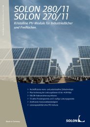
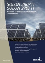
SOLON SOLbond PLUS · EN<br />
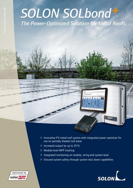
SOLON SOLbond +<br />
The Power-Optimized Solution for Metal Roofs.<br />
Innovative PV metal roof system with integrated power optimizer for<br />
use on partially shaded roof areas<br />
Increased output by up to 25 %<br />
Module level MPP tracking<br />
Integrated monitoring on module, string and system level<br />
Ensured system safety through system shut down capabilities
With SOLON SOLbond + Greater Output<br />
on Partially Shaded Metal Roofs.<br />
SOLON SOLbond+ is the ideal solution for partially shaded metal roofs. This innovative photovoltaic<br />
system now features an integrated power optimizer, resulting in an up to 25 % greater output.<br />
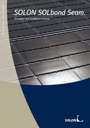
SOLON SOLbond.<br />
The SOLON SOLbond photovoltaic system has been specially designed for metal roofs and can be<br />
installed extremely quickly and easily – sometimes without even the need for roof penetration. The<br />
frameless crystalline SOLON modules are bonded either directly to the roof membrane or by means of a<br />
rail, thereby ensuring a high area output. Weighing between 10.2 kg/m 2 (SOLON SOLbond Integra with<br />
power optimizer) and 11.2 kg/m 2 (SOLON SOLbond Rail/Seam with power optimizer), the system can<br />
even be installed on roofs with a low load-bearing reserve.<br />
Power Optimizer.<br />
The power optimizer is at the heart of SOLON SOLbond+. It replaces the traditional junction box and is<br />
also responsible for determining the individual, maximum power point (MPP) of each individual module.<br />
This means that a shaded module no longer affects the output of the entire module string. Thanks to this<br />
function, partially shaded roof areas – for example, due to a skylight, chimney or lightning conductor – are<br />
now suitable for the installation and economical operation of a solar power system. For system owners,<br />
this means up to 25 % greater output. The power optimizer also enables different string lengths to be<br />
connected to a power inverter, thereby allowing for a flexible system design.<br />
SolarEdge power inverters.<br />
Various power inverter models are available, ranging from 2.2 kWp to 17 kWp (8 – 50 modules/string).<br />
Constant input voltage allows for maximum efficiency of up to 98 %. Integrated SafeDC technology is<br />
a special feature. This function allows the DC voltage to be reduced to a safe level during installation and<br />
maintenance, preventing electric shocks and electric arcs. The system automatically shuts down in the<br />
event of a fire, ensuring maximum safety for installers and system owners.<br />
Monitoring.<br />
+ + +<br />
Web-based monitoring increases the reliability of the solar power system through constant output<br />
surveillance. System data is gathered using an integrated communication unit then transferred to a<br />
server. This means that data on each module, each string, and even the entire system, can be accessed<br />
from anywhere in the world via a password-protected area. Automated warning messages draw attention<br />
to errors accurately and at an early stage, which means that any irregularities are identified before they<br />
affect the solar system. This ensures productive system performance on a permanent basis.<br />
Conditions of use for monitoring can be accessed at www.solon.com/global/solraise.<br />
SolarEdge and SafeDC are trademarks of SolarEdge Technologies, Ltd. in Israel, the United States and other countries.
SOLON SOLbond+<br />
SOLON Black 280/12 PLUS<br />
(monocrystalline)<br />
SOLON Blue 270/12 PLUS<br />
(polycrystalline)<br />
Electrical data – typical (STC)<br />
STC (Standard Test Conditions): 1,000 W/m², (25 ± 2)°C, AM 1.5 in accordance to EN 60904-3<br />
Generator output P max 315 Wp 1) 310 Wp 305 Wp 300 Wp 295 Wp 290 Wp<br />
Module efficiency 15.91 % 15.66 % 15.40 % 15.15 % 14.90 % 14.65 %<br />
Max. Module efficiency<br />
of the Power Optimizer 99.5 % 99.5 % 99.5 % 99.5 % 99.5 % 99.5 %<br />
Rated voltage 2) V mpp 5 – 60 V 5 – 60 V 5 – 60 V 5 – 60 V 5 – 60 V 5 – 60 V<br />
Rated current 2) I mpp 0 – 15 A 0 – 15 A 0 – 15 A 0 – 15 A 0 – 15 A 0 – 15 A<br />
Open circuit current V OC 1 Vdc 1 Vdc 1 Vdc 1 Vdc 1 Vdc 1 Vdc<br />
Maximum system voltage,<br />
predetermined from the inverter<br />
single phase/three phase 500 V/ 950 V 500 V/ 950 V 500 V/ 950 V 500 V/ 950 V 500 V/ 950 V 500 V/ 950 V<br />
Measuring tolerance for P max: ± 3%<br />
Reduction of module efficiency from 1,000 W/m² to 200 W/m² : < 4 %<br />
Electrical data – typical (NOCT)<br />
NOCT (Nominal Operating Cell Temperature): 800 W/m², NOCT, AM 1.5<br />
Power rating P max 226 Wp 222 Wp 219 Wp 215 Wp 212 Wp 208 Wp<br />
Rated voltage 2 ) V mpp 5 – 60 V 5 – 60 V 5 – 60 V 5 – 60 V 5 – 60 V 5 – 60 V<br />
Rated current 2 ) I mpp 0 – 15 A 0 – 15 A 0 – 15 A 0 – 15 A 0 – 15 A 0 – 15 A<br />
Open circuit voltage V OC 1 Vdc 1 Vdc 1 Vdc 1 Vdc 1 Vdc 1 Vdc<br />
Thermal data<br />
Tc of power – 0.43 %/K<br />
NOCT (according to IEC 61215) 48°C ± 2°C<br />
Measuring tolerance for all final data: ± 10 % (except P max (STC) and NOCT)<br />
Electrical data – typical (STC)<br />
STC (Standard Test Conditions): 1,000 W/m², (25 ± 2)°C, AM 1.5 in accordance to EN 60904-3<br />
Generator output P max 305 Wp 1) 300 Wp 295 Wp 290 Wp 285 Wp 280 Wp<br />
Module efficiency 15.40 % 15.15 % 14.90 % 14.65 % 14.39 % 14.14 %<br />
Max. Module efficiency<br />
of the Power Optimizer 99.5 % 99.5 % 99.5 % 99.5 % 99.5 % 99.5 %<br />
Rated voltage 2) V mpp 5 – 60 V 5 – 60 V 5 – 60 V 5 – 60 V 5 – 60 V 5 – 60 V<br />
Rated current 2) I mpp 0 – 15 A 0 – 15 A 0 – 15 A 0 – 15 A 0 – 15 A 0 – 15 A<br />
Open circuit current V OC 1 Vdc 1 Vdc 1 Vdc 1 Vdc 1 Vdc 1 Vdc<br />
Maximum system voltage,<br />
predetermined from the inverter<br />
single phase/three phase 500 V/ 950 V 500 V/ 950 V 500 V/ 950 V 500 V/ 950 V 500 V/ 950 V 500 V/ 950 V<br />
Measuring tolerance for P max: ± 3%<br />
Reduction of module efficiency from 1,000 W/m² to 200 W/m² : < 5 %<br />
Electrical data – typical (NOCT)<br />
NOCT (Nominal Operating Cell Temperature): 800 W/m², NOCT, AM 1.5<br />
Power rating P max 222 Wp 218 Wp 215 Wp 211 Wp 207 Wp 204 Wp<br />
Rated voltage 2 ) V mpp 5 – 60 V 5 – 60 V 5 – 60 V 5 – 60 V 5 – 60 V 5 – 60 V<br />
Rated current 2 ) I mpp 0 – 15 A 0 – 15 A 0 – 15 A 0 – 15 A 0 – 15 A 0 – 15 A<br />
Open circuit voltage V OC 1 Vdc 1 Vdc 1 Vdc 1 Vdc 1 Vdc 1 Vdc<br />
Thermal data<br />
Tc of power – 0.41 %/K<br />
NOCT (according to IEC 61215) 46°C ± 2°C<br />
Measuring tolerance for all final data: ± 10 % (except P max (STC) and NOCT)<br />
Inverter single phase 3) three phase 3)<br />
Dimensions (B x W x H) 540 x 315 x 191 mm 540 x 315 x 260 mm<br />
Weight 23 kg 32 kg<br />
Max. efficiency 97.6 % 98 %<br />
Operating temperature range – 20°C to + 50°C – 20°C to + 60°C<br />
1 ) Available in limited amounts upon request.<br />
2) Depending on system configuration.<br />
3) For further technical data please refer to the manufacturer's inverter datasheet.
SOLON SOLbond PLUS · 02/13 · EN<br />
2) According to SOLON SOLbond Integra / Rail / Seam Terms and Conditions of<br />
Warranty and Guarantee. Valid for roofs approved by SOLON.<br />
3) According to the SolarEdge Limited Product Warranty.<br />
*) For other components please refer to the installation manual.<br />
All necessary components are being delivered for installation.<br />
1) According to SOLON Product and Performance Guarantee.<br />
SOLON SOLbond+<br />
SOLON Black 280/12 PLUS and SOLON Blue 270/12 PLUS.<br />
MODULE<br />
Mechanische Daten<br />
Dimensions (H x W x D) 1,973 x 993 x 4,5 mm<br />
Weight 2.1 kg<br />
Junction box 1 box with 3 bypass diodes (IP65)<br />
Cable Solar cable, length 1.000 mm, 6 mm²,<br />
prefabricated with MC4-combinable plug (IP67)<br />
Application class Class A at IEC 61730<br />
Front glass Transparent toughened safety glass, 3.2 mm<br />
Solar cells 72 cells, mono- or polycrystalline Si 6.2˝ (156 x 156 mm)<br />
Cell encapsulation EVA (Ethylene Vinyl Acetate)<br />
Back side Composite film<br />
Permissible operating conditions<br />
Temperature range –40°C to + 85°C<br />
Maximum surface load capacity Tested up to 2,400 Pa according to IEC 61215<br />
Resistance against hail Maximum diameter of 25 mm with impact speed of 83 km/h<br />
OTHER COMPONENTS*<br />
Assembly rail SOLON SOLbond Integra SOLON SOLbond Rail SOLON SOLbond Seam<br />
Material<br />
SOLON Energy GmbH Phone + 49 30 81879 - 0<br />
Am Studio 16 Fax + 49 30 81879 - 9999<br />
12489 Berlin • Germany E-Mail rooftops@solon.com<br />
–<br />
GRP (Class E23<br />
after DIN 13706)<br />
Anodised aluminium<br />
Dimension (H x W x D) – 2,000 x 25 x 9.7 mm 6,000 mm length<br />
Rivet SOLON SOLbond Integra SOLON SOLbond Rail SOLON SOLbond Seam<br />
Material – Aluminum / stainless steel –<br />
Sikasil® SG-20<br />
Container size 600 ml<br />
Chemical characteristics 1-component silicone, moisture-curing, neutrally cross-linked<br />
Working temperature +5 °C to +40 °C<br />
Use –40 °C to +150 °C<br />
SYSTEM<br />
Operating conditions SOLON SOLbond Integra SOLON SOLbond Rail SOLON SOLbond Seam<br />
Permissible roof pitch 3 – 30° 3 – 15° Project-specific<br />
Roof profile<br />
Static proof<br />
New trapezoidal and<br />
sandwich profiles made<br />
of steel with high<br />
performing Colorcoat<br />
Prisma® by Tata Steel<br />
Steel frame must permit<br />
additional load of<br />
SOLON SOLbond Integra<br />
of 10 kg/m 2<br />
Trapezoidal and sandwich<br />
profiles made of<br />
steel with a sheet<br />
thickness of min. 5 mm<br />
(outer shell)<br />
Steel frame must permit<br />
additional load of<br />
SOLON SOLbond Rail<br />
of 11 kg/m 2<br />
Industrially manufactured<br />
standing seam<br />
roof with round head<br />
profile<br />
Steel frame must permit<br />
additional load of<br />
SOLON SOLbond Seam<br />
of 11 kg/m 2<br />
Guarantees and certifications SOLON SOLbond Integra SOLON SOLbond Rail SOLON SOLbond Seam<br />
Product guarantee module 10 years 1) 10 years 1) 10 years 1)<br />
Warranty on adhesive bonding Up to 25 years 2 ) Up to 20 years 2 ) Up to 20 years 2 )<br />
Inverter product guarantee 12 years 3) 12 years 3) 12 years 3)<br />
PowerOptimizer product guarantee 25 years 3) 25 years 3) 25 years 3)<br />
Performance guarantee module Guaranteed output of 95 % for 5 years, 90 % for 10 years,<br />
87 % for 15 years, 83 % for 20 years and 80 % for 25 years 1 )<br />
Approvals and certificates<br />
module<br />
IEC 61215 Edition II, IEC 61730 (incl. Safety Class II), IEC 62716<br />
(Ammonia resistance), IEC 68-2-52 (Salt mist resistance), MCS<br />
EMC / Safety IEC 61000-6-2; IEC 61000-6-3; IEC 62103, IEC 62109<br />
Approvals and certificates<br />
adhesive Fulfils requirements of EOTA ETAG 002, EN 13022, ASTM C 1184<br />
This datasheet complies with the requirements of EN 50380:2003. Subject to modifications and omissions.<br />
Electrical data without guarantee.<br />
Colorcoat Prisma and Galvalloy are trademarks of Tata Steel UK Limited.<br />
Drawing<br />
993 ± 2<br />
420 ± 5<br />
1,973 ± 2<br />
75 ± 5<br />
4.5<br />
Dimensions in mm<br />
For more information on SOLON products<br />
please visit www.solon.com