ASSEMBLY INSTRUCTIONS S O L O N STANDARD MODULES
ASSEMBLY INSTRUCTIONS S O L O N STANDARD MODULES
ASSEMBLY INSTRUCTIONS S O L O N STANDARD MODULES

You also want an ePaper? Increase the reach of your titles
YUMPU automatically turns print PDFs into web optimized ePapers that Google loves.
Technical Service<br />
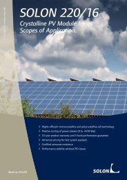
<strong>ASSEMBLY</strong> <strong>INSTRUCTIONS</strong> SOLON <strong>STANDARD</strong> <strong>MODULES</strong><br />
SOLON modules may only be assembled by qualified specialist firms. Please observe the standards and<br />
regulations relevant for PV systems, like VDE regulations (German Association for Electrical, Electronic &<br />
Information Technologies), DIN standards, VDEW guideline (German Power Industries Association), the TAB<br />
(technical connection conditions) of the responsible network operators as well as the rules of the Employer's<br />
Liability Insurance Associations for industrial safety. Non-compliance may result in considerable personal<br />
injuries and damage to property.<br />
The basis for the dimensioning, the rating and the constructive realization of solar systems with SOLON<br />
modules on roof constructions and support frames are the currently valid standards and regulations like<br />
DIN 1055 Part 4 Wind Load (Version March 2005) and DIN 1055 Part 5 Snow Load (Version July 2005).<br />
The new series of standards that have begun to govern the effects and load assumptions in Germany since<br />
January 2007, contain values for the formulation of wind and snow loads that are considerably more<br />
precise.<br />
The snow load on the ground s k in kN/m² to be considered in Germany results from the respective<br />
snow load zone, the location of the building and the ground level elevation above seal level (see Annex 1<br />
for snow load on the ground).<br />
The wind load to be considered must be determined for the location of the project from the wind zones<br />
map which allows for the location of the site as well as for four wind zones. For buildings up to a height of<br />
25 m, the wind load can be determined using a simplified procedure. Depending on the height of the<br />
building, the wind load is specified as Speed Pressure q in kN/m² (Annex 2).<br />
In order to retain a practical default, the allowable snow load to the ground s kallow must be taken from<br />
the tables and compared with the snow load to the ground to be applied s k . The requirements for an<br />
assembly approval for the modules are met if the allowable snow load according to the table is larger than<br />
the snow load to be applied for the location of the assembly, thus s kallow ≥ s k . Favorable assembly conditions<br />
will allow the use of the modules at the largest applicable wind and snow loads according to DIN 1055. In<br />
order to avoid increased stress on the modules in the edge zones and corner areas, it is necessary to<br />
maintain minimum distances from the edges of buildings or to carry out separate calculations.<br />
The calculation results (Annex 3 through 6) are also based on the DIN 1055-100, Effects on Supporting<br />
Structures (March 2001) and the DIN 4113, Aluminum Constructions (September 2002). The effects<br />
resulting from the dead weight of the modules, wind and snow have not been considered individually, but<br />
have been combined with regard to their probability of occurrence.<br />
Clearance of the depicted types of assembly is granted up to the maximum resulting load carrying<br />
capacity of the surface in kg per m 2 of module surface (Table 1) that is specified for the module type<br />
and which may not be exceeded. Depending on the support and attachment area (maximum or optimal)<br />
and on the arrangement of the modules (vertical or horizontal), the maximum resulting load carrying<br />
capacity of the surface can be determined.<br />
as at: 08/07/2009 phone: +49 30 81879 0 fax: +49 30 81879 9999 www.solon.com 5