
Create successful ePaper yourself
Turn your PDF publications into a flip-book with our unique Google optimized e-Paper software.
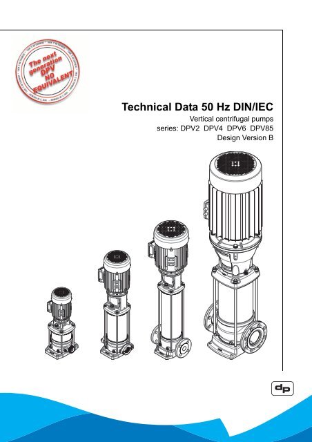
<strong>Technical</strong> <strong>Data</strong> <strong>50</strong> <strong>Hz</strong> <strong>DIN</strong>/<strong>IEC</strong><br />
Vertical centrifugal pumps<br />
series: DPV2 DPV4 DPV6 DPV85<br />
Design Version B
Table of Contents<br />
1 Pump introduction<br />
1.1 General .................................................................................................................................................. 4<br />
1.2 Model key............................................................................................................................................... 4<br />
1.3 Operation ............................................................................................................................................... 5<br />
1.4 Measuring, draining and venting............................................................................................................ 5<br />
1.5 Working range........................................................................................................................................ 5<br />
1.6 Basic material variants........................................................................................................................... 6<br />
1.7 Pump bearing......................................................................................................................................... 6<br />
1.8 Modular selection................................................................................................................................... 6<br />
1.9 Approvals ............................................................................................................................................... 7<br />
2 Performance characteristics<br />
2.1 Performance range ................................................................................................................................ 8<br />
2.2 Performance curve details ..................................................................................................................... 8<br />
2.3 Performance with variable frequency drive.......................................................................................... 10<br />
2.4 How to read the values from the curves ...............................................................................................11<br />
2.5 Hydraulic performance curve DPV(C/S) 2 B <strong>50</strong> <strong>Hz</strong> ............................................................................. 12<br />
2.6 Hydraulic performance curve DPV(C/S) 4 B <strong>50</strong> <strong>Hz</strong> ............................................................................. 13<br />
2.7 Hydraulic performance curve DPV(C/S) 6 B <strong>50</strong> <strong>Hz</strong> ............................................................................. 14<br />
2.8 Hydraulic performance curve DPV(C/S)F 85 B <strong>50</strong> <strong>Hz</strong> ......................................................................... 15<br />
3 Dimensions<br />
3.1 DPV 2 B - <strong>50</strong><strong>Hz</strong> - 2 pole - <strong>DIN</strong> ............................................................................................................. 16<br />
3.2 DPV 4 B - <strong>50</strong><strong>Hz</strong> - 2 pole - <strong>DIN</strong> ............................................................................................................. 18<br />
3.3 DPV 6 B - <strong>50</strong><strong>Hz</strong> - 2 pole - <strong>DIN</strong> ............................................................................................................. 20<br />
3.4 DPV(C/S) F 85 B <strong>50</strong><strong>Hz</strong> - 2 pole - <strong>DIN</strong>.................................................................................................. 22<br />
4 Seals<br />
4.1 Mechanical seal option specifications.................................................................................................. 24<br />
5 Motors and motor options<br />
5.1 General ................................................................................................................................................ 25<br />
6 Accessories<br />
6.1 Horizontal mounting kit (optional) ........................................................................................................ 26<br />
6.2 Thrust bearing housing (optional) ........................................................................................................ 27<br />
7 Materials<br />
7.1 Parts overview ..................................................................................................................................... 28<br />
8 Medium handled<br />
8.1 Medium handled .................................................................................................................................. 34<br />
3
4<br />
1 Pump introduction<br />
1.1 General The vertical, single or multi stage centrifugal pump<br />
series are designed for pumping clean, or lightly<br />
aggressive, watery mediums.<br />
Suction and discharge of the pump are in-line,<br />
ID3355<br />
making the pump easy to install.<br />
The hydraulic assembly is driven by an electric motor.<br />
All hydraulic parts of the pump are made of stainless<br />
steel.<br />
The vertical, multi-stage centrifugal DPV pumps are<br />
produced by DP-Pumps.<br />
DPVME2 B DPV4 B DPVF6 B DPVCF85 B<br />
1.2 Model key<br />
Table 1: Model key Example DPVSF85/3-1 B<br />
20090719<br />
DP VS F 85 /3 -1 B<br />
Label DP Product Label<br />
Material/Con- VC Cast Iron pump foot and top bracket hydr. 14301 / AISI 304<br />
struction<br />
V All wetted parts Stainless Steel 1.4301 / AISI 304<br />
VM All wetted parts Stainless Steel 1.4301 / AISI 304 with closed coupled motor<br />
VS All wetted parts Stainless Steel 1.4401 / AISI 316<br />
Connections E Male thread (with non-return valve insert)<br />
Oval flange with female thread<br />
F Round flange<br />
V Victaulic connections<br />
T Tri-clamp connections<br />
85 Capacity in m 3 /h at Q. opt.<br />
/3 Number of stages<br />
/3 -1 Number of stages of which one stage with reduced head<br />
B Design version
1.3 Operation<br />
ID3027<br />
A<br />
G<br />
E F<br />
Figure 1: DPVF 85 20080190-A/27022008<br />
During centrifugal operation of the pump an negative<br />
pressure is created at the inlet of the impeller. This<br />
underpressure enables the medium to enter the pump<br />
at the suction connection (A).<br />
Every stage (B) consists of an impeller and diffuser.<br />
The passage of this stage determines the capacity of<br />
the pump. The diameter of the stages is related to the<br />
centrifugal forces and its “stage pressure”: the more<br />
stages, the more pressure.<br />
G<br />
B C<br />
D<br />
This total capacity and raised pressure will be guided<br />
to the outside of the pump, between the pump stages<br />
and the outer sleeve (C) and the medium will leave<br />
the pump at the discharge connection (D).<br />
1.4 Measuring, draining and<br />
venting<br />
The pump is provided with plugs for measuring,<br />
draining and venting.<br />
Connection (E) is meant to drain the inlet part of the<br />
pump. Or to measure the inlet / suction pressure<br />
using a G ¼ connection.<br />
Connection (F) is meant to drain the outlet part of the<br />
pump. Or to measure the discharge pressure using a<br />
G ¼ connection.<br />
Connections (G) are meant to vent the pump system<br />
when the pump is not in operation. Or to measure the<br />
discharge pressure of the pump using a G 3/8<br />
connection.<br />
1.5 Working range<br />
The working range is depending on the application<br />
and a combination of pressure and temperature For<br />
specific and detailed limits advice the working ranges<br />
are described in the chapter 1.8Modular selection.<br />
The overall working range of the pumps can be<br />
summarised as follows:<br />
Table 2: Specification of the working range<br />
Pump type DPV note<br />
Ambient temperature [°C] -20 up to 40 1<br />
Minimum inlet pressure NPSH req. + 1m<br />
Viscosity [cSt] 1-100 2<br />
Density [kg/m 3 ] 1000-2<strong>50</strong>0 3<br />
Cooling forced motor cooling 3<br />
Minimum frequency [<strong>Hz</strong>] 10<br />
Maximum frequency [<strong>Hz</strong>] 60 4<br />
Allowable size of solids<br />
pumped<br />
[5µm] to [1mm]<br />
1. If the ambient temperature exceeds the above value or<br />
the motor is located more than 1000 m above sea<br />
level, the motor cooling is less effective and could<br />
require an adapted motor power. See table 9: Motor<br />
load dep. sea level or amb. temp or please contact<br />
your supplier for more detailed advice.<br />
2. Deviation in viscosity and/or density could require an<br />
adapted motor power. Please contact your supplier for<br />
more detailed advice.<br />
3. The free space above the motor cooling fan must be at<br />
least 1/4 of the diameter of the inlet of the cooling fan<br />
in order to have a sufficient flow of (cooling) air.<br />
5
6<br />
4. Pumps that are intended for <strong>50</strong> <strong>Hz</strong> operation, may not<br />
be connected to 60 <strong>Hz</strong> power supply.<br />
1.5.1 Minimum capacity<br />
For minimum capacity at medium temperature of<br />
20 o C, see table 3Minimum capacity (Qmin); for<br />
higher temperatures, see table 4Minimum capacity<br />
vs.temperature (in % of Q optimum)<br />
To prevent the pump from overheating, gathering gas,<br />
cavitation etc. a minimum capacity has to be secured.<br />
The minimum capacity corresponds to al percentage<br />
of the optimum flow Q opt in relation to the temperature<br />
of the liquid pumped.<br />
Table 3: Minimum capacity (Q min )<br />
size Qmin [m3 /h]<br />
<strong>50</strong> <strong>Hz</strong> - 2 pole 60 <strong>Hz</strong> - 2 pole<br />
2 0.2 0.25<br />
4 0.4 0.4<br />
6 0.6 0.7<br />
85 8.5 10.2<br />
Table 4: Minimum capacity vs.temperature (in % of Q<br />
optimum)<br />
Q [%]<br />
ID2312<br />
30<br />
25<br />
20<br />
15<br />
10<br />
5<br />
0<br />
40 <strong>50</strong> 60 70 80 90 100 110 120<br />
1.5.2 Ambient temperature and higher<br />
altitude<br />
If the ambient temperature exceeds the above value<br />
or the motor is located more than 1000 m above sea<br />
level, the motor cooling is less effective and could<br />
require an adapted motor power. See Tabel: 6<br />
Ambient Temperature [°C] above sea level [m] or<br />
please contact your supplier for more detailed advice.<br />
Table 5: Ambient Temperature [°C]<br />
Ambient temperature<br />
[°C]<br />
Above sea level<br />
[m]<br />
motor load<br />
20 1000 100%<br />
25 1000 100%<br />
30 1000 100%<br />
35 1000 100%<br />
40 1000 100%<br />
t [°C]<br />
2312/29072004<br />
Ambient temperature<br />
[°C]<br />
45 1625 98%<br />
<strong>50</strong> 22<strong>50</strong> 95%<br />
55 2875 90%<br />
60 3<strong>50</strong>0 85%<br />
65 4125 80%<br />
70 47<strong>50</strong> 75%<br />
Table 6: Ambient Temperature [°C] above sea level<br />
[m]<br />
ID3422<br />
Above sea level<br />
[m]<br />
1.6 Basic material variants<br />
Table 7: Basic material variants<br />
Model Hydraulic Casing Sealing<br />
V 1.4301 1.4308 EPDM<br />
VS 1.4404 1.4408 Viton<br />
VC 1.4301 JL1040 EPDM<br />
1.7 Pump bearing<br />
Medium lubricated stage bearing<br />
Tungsten Carbide against Ceramic<br />
1.8 Modular selection<br />
motor load<br />
To suit almost every application the pump is<br />
assembled out of modules which can be selected<br />
depending on the required working range.<br />
Basic modules are:<br />
• Basic pump model, which defines the capacity,<br />
pressure and basic material<br />
• Connections, which define the suction and<br />
discharge connection as well as the base plate.<br />
• Sealings, which define the elastomers, the<br />
mechanical seal and the shaft seal type.<br />
• Electric motor, which defines all requirements<br />
of the motor such as motor size, power, voltage,<br />
frequency and all possible motor accessories.<br />
3422/09112009
1.9 Approvals<br />
CE Conformity with European Safety Directive<br />
ACS Drinking Water Approval (F)<br />
WRc Drinking Water Approval (GB)<br />
ATEX Conformity with “ATmosphères EXplosibles”<br />
Directive<br />
7
8<br />
2 Performance characteristics<br />
2.1 Performance range<br />
ID3429<br />
Figure 2: Performance range DPV 2,4,6 & 85 <strong>50</strong> <strong>Hz</strong><br />
2.2 Performance curve details<br />
The performance diagrams give a global overview of<br />
all the pump models the shaded models are<br />
mentioned in this documentation. Detailed<br />
characteristics are given for each model showing the<br />
hydraulic efficiency, NPSH req, and shaft power as<br />
well.<br />
The performance of the pump depends on the<br />
number of stages. As per example:<br />
DPV 4/2: model DPV 4 2 stages with 2 full head<br />
impellers<br />
DPV 85/4-1 model DPV 85 4 stages with 3 full head<br />
impellers and 1 reduced<br />
impeller<br />
The detailed performance curves are in accordance<br />
with ISO 9906 Annex A.<br />
The motors used for the measurements are calibrated<br />
motors with a specific rotational speed. Therefore the<br />
performance data, like Q/H, efficiency and shaft
power used for published curves are converted to the<br />
average speed per motor power. To refine this data<br />
the published data has to be corrected accordingly.<br />
The published curves and data mentioned on the<br />
pump are based on the following rotational speed:<br />
Table 8: Rated motor power and speed<br />
Rated motor<br />
power<br />
Rated speed at<br />
<strong>50</strong> <strong>Hz</strong> [rpm]<br />
0.37 and 0.55 kW 2800 3460<br />
to 2.2 kW 2880 3460<br />
to 3 kW 2920 3510<br />
to 4 kW 2920 3510<br />
to 5.5 kW 2940 3530<br />
to 7.5 kW 2940 3530<br />
to 15 kW 29<strong>50</strong> 3530<br />
to 22 kW 29<strong>50</strong> 35<strong>50</strong><br />
to 45 kW 2960 35<strong>50</strong><br />
Rated speed at<br />
60 <strong>Hz</strong> [rpm]<br />
The characteristics given are based on:<br />
• De-aerated water at a temperature of 20 °C<br />
• Density of 1.0 kg/dm 3<br />
• Kinematical viscosity of 1 mm 2 /s (1 cst)<br />
To prevent the pump from overheating, gathering gas,<br />
cavitation etc. a minimum capacity has to be secured.<br />
The minimum capacity corresponds to a percentage<br />
of the optimum flow Q opt in relation to the temperature<br />
of the liquid pumped.<br />
9
10<br />
2.3 Performance with variable<br />
frequency drive<br />
The minimum frequency of the DP motor should be<br />
limited to 10 <strong>Hz</strong> to ensure sufficient cooling. When the<br />
rotational speed exceeds the nominal speed of the<br />
motor, make sure that the power output of the motor<br />
is suitable to drive the corresponding pump model.<br />
ID3238<br />
The performance of the pump differs from the fixed<br />
speed performance according to the recalculation<br />
scheme.<br />
Figure 3: Performance characteristics 3238/08072008
2.4 How to read the values from<br />
the curves<br />
To find the required hydraulic information from the<br />
published curves, it is important to know the<br />
application in which the pump has to be installed.<br />
There are two main distinction to be made:<br />
3227<br />
O Calculated duty point<br />
Actual hydraulic performance<br />
A Flow determined<br />
B Pressure determined<br />
A Flow determined (like booster sets and<br />
cleaning) → Opening taps<br />
B Pressure determined (like boiler feed and<br />
reverse osmosis systems) → Facing counter<br />
pressure.<br />
Figure 4: How to read the values from the curves 3227/04072008<br />
Pump size / no of stages.<br />
Installed motor power<br />
Capacity @ Pressure<br />
NPSH (m)<br />
Hydraulic efficiency (%)<br />
Required power (P2)<br />
11
12<br />
2.5 Hydraulic performance curve DPV(C/S) 2 B <strong>50</strong> <strong>Hz</strong><br />
ID3424<br />
Figure 5: Performance curve DPV(C/S) 2 B <strong>50</strong> <strong>Hz</strong> 20090370-C
2.6 Hydraulic performance curve DPV(C/S) 4 B <strong>50</strong> <strong>Hz</strong><br />
ID3448<br />
Figure 6: Performance curve DPV(C/S) 4 B <strong>50</strong> <strong>Hz</strong> 20090372-C<br />
13
14<br />
2.7 Hydraulic performance curve DPV(C/S) 6 B <strong>50</strong> <strong>Hz</strong><br />
ID3425<br />
Figure 7: Performance curve DPV(C/S) 6 B <strong>50</strong> <strong>Hz</strong> 20090374-C
2.8 Hydraulic performance curve DPV(C/S)F 85 B <strong>50</strong> <strong>Hz</strong><br />
ID3229<br />
Figure 8: Performance curve DPV(C/S)F 85 B <strong>50</strong> <strong>Hz</strong> 20080076-A/26062008<br />
15
16<br />
3 Dimensions<br />
3.1 DPV 2 B - <strong>50</strong><strong>Hz</strong> - 2 pole - <strong>DIN</strong><br />
Table 9: VM CLOSED coupled motor Construction type; IM 3619<br />
ID3343<br />
20081033-E<br />
Connection Min. pressure<br />
class<br />
options<br />
Table 10: V Long coupled motor Construction type; V18<br />
ID3436<br />
20091216-A/30112009<br />
DPV(S) -/E/V/T DPV(C/S)F<br />
Model<br />
[kW] E1 E2 F1 F1<br />
2/2 PN10 0.37 138 109 420 445<br />
2/3 0.37 138 109 441 466<br />
2/4 0.37 138 109 463 488<br />
2/5 0.37 138 109 484 <strong>50</strong>9<br />
2/6 0.55 138 109 <strong>50</strong>6 531<br />
Connection Min. pressure<br />
class<br />
options<br />
DPV(S) -/E/V/T DPV(C/S)F<br />
Model<br />
[kW] E1 E2 F1 F2 F1 F2<br />
2/2 PN10 0.37 138 109 472 259 497 284<br />
2/3 0.37 138 109 493 280 518 305<br />
2/4 0.37 138 109 515 302 540 327<br />
2/5 0.37 138 109 536 323 561 348<br />
2/6 0.55 138 109 558 345 583 370<br />
2/7 0.55 138 109 579 366 604 391<br />
2/8 0.55 138 109 601 398 626 423<br />
2/9 0.75 160 1<strong>50</strong> 676 419 701 444<br />
2/10 0.75 160 1<strong>50</strong> 698 441 723 466<br />
2/11 1.10 160 1<strong>50</strong> 719 462 744 487<br />
2/12 1.10 160 1<strong>50</strong> 741 484 766 <strong>50</strong>9<br />
2/14<br />
1.10 160 1<strong>50</strong> 784 527 809 552<br />
2/16 PN16 1.<strong>50</strong> 185 160 833 580 858 605<br />
2/18 1.<strong>50</strong> 185 160 876 623 901 648<br />
2/20 1.<strong>50</strong> 185 160 919 666 944 691<br />
2/22<br />
2.20 185 160 991 709 1016 734<br />
2/24 PN25 2.20 185 160 1034 752 1059 777<br />
2/26<br />
PN40<br />
2.20 185 160 1077 795 1102 820<br />
2/28 2.20 185 160 1120 838 1145 863<br />
2/30 2.20 185 160 1163 881 1188 906
ID3345<br />
ID 3484<br />
ID3351<br />
ID3352<br />
ID33<strong>50</strong><br />
ID3348<br />
20090617-A<br />
20100156<br />
20090626-A<br />
20090625-A<br />
20090624-A<br />
20090623-A<br />
DPV E Male thread -<br />
With non return valve insert at discharge side<br />
and pressure measurement plug at upstream<br />
side<br />
Norm: G EN ISO 228<br />
Size: G 6/4<br />
Pressure Class: PN16<br />
Option: Base plate in Cast SS 1.4308<br />
DPV (S)<br />
Counter flange with female thread included<br />
DPV: Cataphoric coated cast iron<br />
DPVS: Cast Stainless steel 1.4408<br />
Norm: G EN ISO 228<br />
Size: G1<br />
Pressure Class: PN16<br />
Option: SS 1.4308 flange and base plate<br />
DPV (S) V VIctaulic<br />
Norm: -<br />
Size: 42.2<br />
Pressure Class: PN25<br />
Option: Base plate in cast SS 1.4308<br />
DPV S T Tri-Clamp<br />
Norm: 32676<br />
Size: DN32<br />
Pressure Class: PN16<br />
Option: Base plate in cast SS 1.4308<br />
DPV C F Cast iron flange<br />
Norm: EN 1092-1/1092-2<br />
Size: NW25<br />
Pressure Class: PN40<br />
DPV (S) F Round collar flange<br />
Cataphoric coated collar flange<br />
Norm: EN 1092-1/1092-2<br />
Size: NW25<br />
Pressure Class: PN40<br />
Option: Collar flange and/or<br />
base plate in cast SS 1.4308<br />
17
18<br />
3.2 DPV 4 B - <strong>50</strong><strong>Hz</strong> - 2 pole - <strong>DIN</strong><br />
Table 11: VM CLOSED coupled motor Construction type; IM 3619<br />
ID3343<br />
20081033-E<br />
Connection Min. pressure<br />
class<br />
options<br />
Table 12: V Long coupled motor Construction type; V18<br />
ID3436<br />
20091216-A/30112009<br />
DPV(S) -/E/V/T DPV(C/S)F<br />
Model<br />
[kW] E1 E2 F1 F1<br />
4/2 PN10 0.37 138 109 420 453<br />
4/3 0.55 138 109 441 466<br />
4/4 0.55 138 109 463 488<br />
4/5 0.75 160 1<strong>50</strong> 528 553<br />
4/6 1.1 160 1<strong>50</strong> 5<strong>50</strong> 573<br />
Connection Min. pressure<br />
class<br />
options<br />
DPV(S) -/E/V/T DPV(C/S)F<br />
Model<br />
[kW] E1 E2 F1 F2 F1 F2<br />
4/2 PN10 0.37 138 109 472 259 497 284<br />
4/3 0.55 138 109 493 280 518 305<br />
4/4 0.55 138 109 515 302 540 327<br />
4/5 0.75 160 1<strong>50</strong> 590 333 615 358<br />
4/6 1.1 160 1<strong>50</strong> 612 355 637 380<br />
4/7 1.1 160 1<strong>50</strong> 633 376 658 401<br />
4/8 1.5 185 160 661 408 686 433<br />
4/9 1.5 185 160 682 429 707 454<br />
4/10 1.5 185 160 704 451 729 476<br />
4/11 2.2 185 160 754 472 779 497<br />
4/12<br />
2.2 185 160 776 494 801 519<br />
4/14 PN16 2.2 185 160 819 537 844 562<br />
4/16 3 205 175 904 590 929 615<br />
4/18 3 205 175 947 633 972 658<br />
4/20<br />
3 205 175 990 676 1015 701<br />
4/22 PN25 4 220 190 1042 719 1067 744<br />
4/24<br />
PN40<br />
4 220 190 1085 762 1110 787<br />
4/26 4 220 190 1128 805 1153 830
ID3345<br />
ID 3484<br />
ID3351<br />
ID3352<br />
ID33<strong>50</strong><br />
ID3348<br />
20090617-A<br />
20100156<br />
20090626-A<br />
20090625-A<br />
20090624-A<br />
20090623-A<br />
DPV E Male thread -<br />
With non return valve insert at discharge side<br />
and pressure measurement plug at upstream<br />
side<br />
Norm: G EN ISO 228<br />
Size: G 6/4<br />
Pressure Class: PN16<br />
Option: Base plate in cast SS 1.4308<br />
DPV (S)<br />
Counter flange with female thread included<br />
DPV: Cataphoric coated cast iron<br />
DPVS: Cast Stainless steel 1.4408<br />
Norm: G EN ISO 228<br />
Size: G1<br />
Pressure Class: PN16<br />
Option: Base plate & flange in SS 1.4308<br />
DPV (S) V VIctaulic<br />
Norm: -<br />
Size: 42.2<br />
Pressure Class: PN25<br />
Option: Base plate in cast SS 1.4308<br />
DPV S T Tri-Clamp<br />
Norm: 32676<br />
Size: DN32<br />
Pressure Class: PN16<br />
Option: Base plate in cast SS 1.4308<br />
DPV C F Cast iron flange<br />
Norm: EN 1092-1/1092-2<br />
Size: NW25<br />
Pressure Class: PN40<br />
DPV (S) F Round collar flange<br />
Cataphoric coated collar flange<br />
Norm: EN 1092-1/1092-2<br />
Size: NW25<br />
Pressure Class: PN40<br />
Option: Collar fland and/or<br />
base plate in cast SS 1.4308<br />
19
20<br />
3.3 DPV 6 B - <strong>50</strong><strong>Hz</strong> - 2 pole - <strong>DIN</strong><br />
Table 13: VM CLOSED coupled motor Construction type; IM 3619<br />
ID3343<br />
20081033-E<br />
Table 14: V Long coupled motor Construction type; V18<br />
ID3436<br />
20091216-A/30112009<br />
Table 15: V1 motor<br />
ID3437<br />
20091217<br />
Connection Min. pressure<br />
class<br />
options<br />
DPV(S) -/E/V/T DPV(C/S)F<br />
Model<br />
[kW] E1 E2 F1 F1<br />
6/2 PN10 0.37 138 109 427 452<br />
6/3 0.75 160 1<strong>50</strong> 496 521<br />
6/4 1.1 160 1<strong>50</strong> 521 546<br />
6/5 1.1 160 1<strong>50</strong> 546 571<br />
Connection Min. pressure<br />
class<br />
options<br />
DPV(S) -/E/V/T DPV(C/S)F<br />
Model<br />
[kW] E1 E2 F1 F2 F1 F2<br />
6/2 PN10 0.37 138 109 479 266 <strong>50</strong>4 291<br />
6/3 0.75 160 1<strong>50</strong> 558 301 583 326<br />
6/4 1.1 160 1<strong>50</strong> 583 326 608 351<br />
6/5 1.1 160 1<strong>50</strong> 608 351 633 376<br />
6/6 1.5 185 160 639 386 664 411<br />
6/7 1.5 185 160 664 411 689 436<br />
6/8 2.2 185 160 718 436 743 461<br />
6/9 2.2 185 160 743 461 768 486<br />
6/10 2.2 185 160 768 486 793 511<br />
6/11<br />
3 205 175 835 521 860 546<br />
6/12 PN16 3 205 175 860 546 885 571<br />
6/14 3 205 175 910 596 935 621<br />
6/16 4 220 190 969 646 994 671<br />
6/18 PN25/40 4 220 190 1016 696 1044 721<br />
Connection Min. pressure<br />
class<br />
options<br />
DPV(S) -/E/V/T DPV(C/S)F<br />
Model<br />
[kW] E1 E2 F1 F2 F1 F2<br />
6/20 PN25 5.5 260 220 1168 821.5 1193 847<br />
6/22<br />
PN40<br />
5.5 260 220 1218 871.5 1243 897<br />
6/24 5.5 260 220 1268 921.5 1293 947<br />
6/26 5.5 260 220 1318 971.5 1343 997
ID3345<br />
ID3346<br />
ID3351<br />
ID3352<br />
ID3354<br />
ID3428<br />
20090617-A<br />
20090620-B<br />
20090626-A<br />
20090625-A<br />
20090622-A<br />
20090621-A<br />
DPV E Male thread -<br />
With non return valve insert at discharge side<br />
and pressure measurement plug at upstream<br />
side<br />
Norm: G EN ISO 228<br />
Size: G 6/4<br />
Pressure Class: PN16<br />
Option: Base plate in cast SS 1.4308<br />
DPV (S)<br />
Counter flange with female thread included<br />
DPV: Cataphoric coated cast iron<br />
DPVS: Cast Stainless steel 1.4408<br />
Norm: G EN ISO 228<br />
Size: G 5/4<br />
Pressure Class: PN16<br />
Option: Flange and base plate in SS1.4308<br />
DPV (S) V VIctaulic<br />
Norm: -<br />
Size: 42.2<br />
Pressure Class: PN25<br />
Option: Base plate in SS 1.4308<br />
DPV S T Tri-Clamp<br />
Norm: 32676<br />
Size: DN32<br />
Pressure Class: PN416<br />
Option: Baseplate in cast SS 1.4308<br />
DPV C F Cast iron flange<br />
Norm: EN 1092-1/1092-2<br />
Size: NW32<br />
Pressure Class: PN40<br />
DPV (S) F Round collar flange<br />
Cataphoric coated collar flange<br />
Norm: EN 1092-1/1092-2<br />
Size: NW32<br />
Pressure Class: PN40<br />
Option: Collar flange and/or<br />
base plate in cast SS 1.4308<br />
21
22<br />
3.4 DPV(C/S) F 85 B <strong>50</strong><strong>Hz</strong> - 2 pole - <strong>DIN</strong><br />
ID3439<br />
20091237<br />
Connection Min. pressure<br />
class<br />
options<br />
DPV(C/S)F<br />
Model<br />
[kW] E1 E2 F1 F2<br />
85/1-1 PN10 5.5 233 162 970 641<br />
85/1 7.5 233 162 998 641<br />
85/2-2 11 315 206 1282 780<br />
85/2-1 15 315 206 1282 780<br />
85/2 15 315 206 1282 780<br />
85/3-2 18.5 315 206 1435 889<br />
85/3-1 22 3<strong>50</strong> 225 1484 889<br />
85/3 22 3<strong>50</strong> 225 1484 889<br />
85/4-2<br />
30 400 290 1648 998<br />
85/4-1 PN16 30 400 290 1648 998<br />
85/4 30 400 290 1648 998<br />
85/5-2 37 400 290 1757 1107<br />
85/5-1 37 400 290 1757 1107<br />
85/5 37 400 290 1757 1107<br />
85/6-2<br />
45 466 373 1923 1216<br />
85/6-1 PN25 45 466 373 1923 1216<br />
85/6<br />
PN40<br />
45 466 373 1923 1216
ID3416<br />
ID3417<br />
ID3416<br />
ID3417<br />
20090642<br />
20090643<br />
20090642<br />
20090643<br />
DPV C F Cast iron flange<br />
Norm: <strong>DIN</strong> 2633<br />
Size: NW100<br />
Pressure Class:PN16<br />
DPV C F Cast iron flange<br />
Norm: <strong>DIN</strong> 2633<br />
Size: NW100<br />
Pressure Class:PN25/40<br />
DPV (S) F Round collar flange<br />
Cataphoric coated collar flange<br />
Norm: <strong>DIN</strong> 2633<br />
Size: NW100<br />
Pressure Class: PN16<br />
Option: Collar flange and baseplate in cast<br />
SS1.4308<br />
DPV (S) F Round collar flange<br />
Cataphoric coated collar flange<br />
Norm: <strong>DIN</strong> 2633<br />
Size: NW100<br />
Pressure Class: PN25/40<br />
Option: Collar flange and baseplate in cast<br />
SS1.4308<br />
23
24<br />
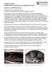
4 Seals<br />
4.1 Mechanical seal option specifications<br />
Table 16: Seal code<br />
Shaft seal Type<br />
Material mechanical<br />
seal<br />
Seal code<br />
Material shaft seal<br />
Material pump<br />
elastomer<br />
Temerature range<br />
shaft seal[ o C]<br />
Max. pressure [bar]<br />
Fixed<br />
Easy Access<br />
MG-G60 B Q1 E GG 11 Ca / SiC / EPDM EPDM -20 - 100 10 <br />
MG-G60 B Q1 V GG 12 Ca / SiC / Viton Viton -20 - 120 10 <br />
RMG-G606 Q1 B E GG 13 SiC / Ca / EPDM EPDM WRc / ACS -20 - 100 25 <br />
RMG-G606 Q1 B V GG 14 SiC / Ca / Viton Viton -20 - 120 (140) 25 (16) <br />
RMG-G606 U3 U3 X4 GG 15 TuC / TuC / HNBR HNBR -20 - 120 (140) 25 (16) <br />
RMG-G606 U3 U3 V GG 16 TuC / TuC / Viton Viton -20 - 120 25 <br />
RMG-G606 U3 B E GG 18 TuC / Ca / EPDM EPDM 559236 -20 - 120 (140) 25 (16) <br />
H7N Q1 A E GG 20 SiC / Ca / EPDM EPDM 559236 -30 - 120 (140) 40 (25) <br />
H7N Q1 A V GG 21 SiC / Ca / Viton Viton -20 - 120 (140) 40 (25) <br />
H7N Q1 A X4 GG 22 SiC / Ca / HNBR HNBR -30 - 120 (140) 40 (25) <br />
RMG-G606 Q1 B E GG 23 SiC / Ca / EPDM EPDM 100 25 <br />
Cartridge
5 Motors and motor options<br />
5.1 General<br />
The standard DP motors are produced conform the<br />
latest technical design, and comply with the<br />
international standards and EU directives regarding<br />
safety measures.<br />
The motors can be specified as:<br />
• T.E.F.C. (totally enclosed fan cooled) Squirrel<br />
cage.<br />
• AC induction motor.<br />
• Protection IP55 (single phase IP54).<br />
• Insulation class F.<br />
• Temperature rise class B.<br />
• Duty class S1.<br />
• Noise levels conform <strong>IEC</strong> 60034-9.<br />
• > 2.2 kW standard 3 x PTC.<br />
The motors come in 3 different<br />
configurations.Mounting in acc. with <strong>IEC</strong>60034-7 and<br />
dimensions in acc. with <strong>IEC</strong> 60072-1<br />
ID3442<br />
V18 flange V1 flange close coupled<br />
20091254<br />
5.2 Options<br />
• Standard motors as per above, but in 4 pole<br />
version (low speed) (DPV(C/S)F 85 B only).<br />
• Standard motors as per above, but IP 54, in<br />
single phase (1x230V).<br />
• Provided with 10 pole industrial connector<br />
“Harting stecker” HAN 10, mounted in stead of<br />
the motor connection box.<br />
• Provided with Rain cover on top of the fan<br />
hood.<br />
• For motors < 3kW provided with 3 x PTC and<br />
anti condensation heater.<br />
• Motor as per above, but manufacturer Siemens<br />
in efficiency class IE 2.<br />
• Motor as per above, but manufacturer VEM/<br />
Dutchi in efficiency class IE 2.<br />
• Explosion proof, class Eex e II T3, make<br />
Siemens.<br />
• Explosion proof, class Eex d II T4, make VEM/<br />
Dutchi.<br />
25
26<br />
6 Accessories<br />
6.1 Horizontal mounting kit<br />
(optional)<br />
In special applications it could be a solution to mount<br />
the pump in a horizontal position. Although the pump<br />
is designed for vertical positioning the hydraulic parts<br />
of the pump are also capable of functioning in a<br />
horizontal position. This option is limited by the motor<br />
rating. The motors of 11kW and above are equipped<br />
with a co-axial bearing which is not suitable for<br />
horizontal positioning.<br />
To ensure a proper and stable horizontal mounting<br />
position for the pump, stainless steel AISI 304<br />
support frames are available. To mount the support<br />
frames, bolts up to a maximum of M12 can be used.<br />
The horizontal mounting kit includes the following<br />
parts:<br />
• Pump bracket support<br />
• Motor flange support<br />
• 4 bolts M12<br />
• 4 washers 12mm<br />
• 4 nuts M12<br />
ID3445<br />
ID2628<br />
Figure 9: DPV 2/4/6/ B horizontal pumps 200<strong>50</strong>451-F<br />
20090417-A<br />
ID3420<br />
ID3420<br />
Figure 10: V(S)F 85 B horizontal pumps 20071047-B<br />
20071047-B
6.1.1 Dimensions of pumps fitted with horizontal mounting kit<br />
Dimensions are related to the dimensions of the<br />
complete pump in standard vertical position and are<br />
mentioned in [mm].<br />
DPV 2/4/6 B V(S)(V) D = 82<br />
V(C/S)F D = 107<br />
Motor [kW] Art. nr. C H A B Weight<br />
[kg]<br />
0.37 - 0.55 2p / 0.25 - 0.37 4p 18707065 F2+49 120 100 100 1.520<br />
0.75 - 1.1 2p / 0.55 - 0.75 4p 18707066<br />
1.5 - 2.2 2p / 1.1 - 1.5 4p 18707067 F2+47<br />
3 - 4 2p / 2.2 - 4 4p 18707068<br />
5.5 - 7.5 2p/4p 18707069 F2-18 170 210 2.280<br />
20090417-A<br />
DPV 85 B V(S)F D = 165<br />
Motor [kW] Art. nr. C H A B Weight<br />
[kg]<br />
5.5 - 7.5 18707064 F2- 16 180 210 2<strong>50</strong> 0.830<br />
20071047-B<br />
6.2 Thrust bearing housing<br />
(optional)<br />
ID3377<br />
Figure 11: Thrust bearing housing 20070627-E<br />
The standard DP-Pumps motors are specially<br />
designed to drive the pump. When a standard motor<br />
has to be installed (or a special motor to fulfill the<br />
applications requirement, like explosion proof, high<br />
efficiency) a special bearing housing must be<br />
installed to relieve the motor of the axial force created<br />
by the pump.<br />
ATTENTION<br />
This option is not applicable for pump<br />
model DPVM.<br />
ATTENTION<br />
Only a motor with a standard key can be<br />
installed with a thrust bearing housing.<br />
ATTENTION<br />
There is no need to change the motor<br />
stool of the pump. The bearing flange<br />
can be mounted on the standard motor<br />
stool of the pump.<br />
27
28<br />
7 Materials<br />
7.1 Parts overview<br />
7.1.1 Part list<br />
Part. no. part description material code Wetted<br />
part<br />
VC V VS<br />
101 Pump casing JL1040 X <br />
1.4308 X <br />
1.4408 X <br />
(Collar) flange JS1030 <br />
1.4308 <br />
10-6 Pump shroud 1.4301 X <br />
1.4404 X <br />
108 Stage Casing DPV 85 B 1.4308 X <br />
1.4408 X <br />
108 Stage Casing DPV 2,4,6 B 1.4301 X <br />
1.4404 X <br />
160 Cover DPV 85 B 1.4308 X <br />
1.4408 X <br />
160 Cover DPV 2,4,6 B 1.4301 X <br />
1.4404 X <br />
210 Shaft 1.4057 X <br />
1.4460 X <br />
230 Impeller DPV 85 B 1.4308 X <br />
1.4408 X <br />
230 Impeller DPV 2,4,6 B 1.4301 X <br />
1.4404 X <br />
341 Motor stool JL1040 X <br />
412 Pump sealing elastomers EPDM X <br />
EPDM WRc/ACS X <br />
Viton X <br />
EPDM E425 X <br />
HNBR X <br />
433 Shaft seal LP (P at Q=0 < 9.2bar) B Q 1 E GG LP X <br />
Q1 B E GG HP1 X <br />
Shaft seal LP (P at Q=0 < 9.2bar) B Q1 V GG LP X <br />
Q1 B V GG HP1 X <br />
45-4 Spacer DPV(C/S) 85 B EPDM X <br />
Viton X <br />
HNBR X <br />
471 Seal cover 1.4308 X <br />
1.4408 X <br />
<strong>50</strong>3 Impeller wear ring DPV 85 B 1.4404 X <br />
525 Spacer sleeve 1.4301 X <br />
1.4404 X <br />
529 Bearing sleeve Tungsten Carbide X <br />
Part of 108 Bearing Aluminium Oxide X <br />
722 Taper piece JL1040 <br />
862 Coupling 5.5 kW JS1030 <br />
Coupling 4 kW Aluminium
Part. no. part description material code Wetted<br />
part<br />
890 Base plate JS1030 <br />
Base plate 1.4308 <br />
Base plate (for F connection) JL1040 <br />
903.02 Screwed plug (drain) 1.4301 (A2) X <br />
1.4404 (A4) X <br />
905 Tie bolt 1.4057 <br />
903.01 Screwed plug (vent) 1.4301 (A2) X <br />
1.4404 (A4) X <br />
920.01 Lock nut 1.4301 X <br />
1.4404 X <br />
930 Safety device Nord-lock 1.4404 X <br />
932 Circlip 1.4571 X <br />
9<strong>50</strong> Wave spring DPV(C/S) 2,4,6 B 1.4301 X <br />
1.4401 X <br />
1. HP: high pressure version > 10 bar (P at Q=0 > 9.2 bar)<br />
Standard Option<br />
7.1.2 Materials conversion<br />
VC V VS<br />
Material Description Code and material nr. Standard ASTM / AISI1 JL 1040 Cast iron GJL-2<strong>50</strong> EN 1561 A48:40B<br />
JS1030 Cast iron GJS-400 EN 1563<br />
1.4057 Chromium-nickel steel X17CrNi16-2--QT800 EN 10088-3 A276:431<br />
1.4301 Chromium-nickel steel X5CrNi18-10 EN 10088 A276:304<br />
1.4305 Chromium-nickel steel X8CrNiS 18-9 EN 10088 A276:303<br />
1.4308 Chromium-nickel cast steel GX5CrNi 19-10 EN 10283 A743:CF8<br />
1.4401 Chromium-nickel-molybdenum steel X5CrNiMo 17-12-2 EN 10088 A276:316<br />
1.4404 Chromium-nickel-molybdenum steel X2CrNiMo 17-12-2 EN 10088 A276:316L<br />
1.4408 Chromium-nickel-molybdenum cast steel GX5CrNiMo 19-11-2 EN 10213 A743CF8M<br />
1.4460 Chromium-nickel-molybdenum steel X3CrNiMoN 27 5 2 EN 10088 --:329<br />
1.4571 Chromium-nickel-molybdenum steel X6CrNiMoTi17-12-2 EN 10088 A276:316Ti<br />
1. Note: The indication of the material designations to ASTM / AISI is not binding<br />
29
30<br />
7.1.3 Sectional drawing DPVCF 2/4/6 B<br />
ID3414<br />
Figure 12: Sectional drawing DPVCF 2/4/6/ B 20080767-E/30112009
7.1.4 Sectional drawing DPV(S) 2/4/6 B<br />
ID3413<br />
Figure 13: Sectional drawing DPV(S) 2/4/6 B 20080766-F/30112009<br />
31
32<br />
7.1.5 Sectional drawing DPVCF 85 B<br />
ID3335<br />
Figure 14: Sectional drawing DPVCF 85 B 20080067-F/30112009
7.1.6 Sectional drawing DPV(S)F 85 B<br />
ID3239<br />
Figure 15: Sectional drawing DPV(S)F 85 B 20080066-E/04062009<br />
33
34<br />
8 Medium handled<br />
8.1 Medium handled<br />
Media description Media group Chemical formula<br />
Cons.<br />
max.<br />
[%]<br />
PH<br />
max.<br />
Temp<br />
max.<br />
{C]<br />
Model Material shaft seal Material<br />
pump<br />
rotor stator elastomer<br />
elastomer<br />
Acetic anhydride Weak acid derivative<br />
(CH3CO) 2O V SiC Ca EPDM EPDM<br />
Aceton Ketone (CH3 ) 2CO VC SiC Ca EPDM EPDM<br />
Alcaline (bottle<br />
rinse)<br />
Rinsing 0.02 < 9.5 40 V TuC TuC HNBR HNBR<br />
Alcohol (Ethanol) Hydrocarbon C2H5OH 1 60 V SiC Ca EPDM EPDM<br />
Alum (potassium<br />
alumminium sulphate)<br />
Salt MI MIII (SO4) 2 0.03 80 VS SiC Ca Viton Viton<br />
Aluminium chloride Halide AlCl3 0.05 <strong>50</strong> VS SiC Ca EPDM EPDM<br />
Aluminium chloride Halide AlCl3 0.1 20 VS SiC Ca EPDM EPDM<br />
Aluminium chloride Halide AlCl3 0.25 20 VS SiC Ca EPDM EPDM<br />
Aluminium sulphate Salt Al2 (SO4 ) 3 20 V SiC Ca EPDM EPDM<br />
Aluminium sulphate Salt Al2 (SO4 ) 3 0.05 60 V TuC TuC Viton Viton<br />
Aluminium sulphate Salt Al2 (SO4 ) 3 0.05 Boiling VS SiC Ca EPDM EPDM<br />
Ammonia Strong base NH3 VC SiC Ca EPDM EPDM<br />
Ammonium bicarbonate<br />
Salt (NH4 )HCO3 0.1 40 V SiC Ca EPDM EPDM<br />
Ammonium sulphate Salt (NH4) 2SO4 0.2 60 V SiC Ca EPDM EPDM<br />
Antifreeze (glykol<br />
base, salt-free)<br />
Alcohol 0.45 110 V SiC Ca EPDM EPDM<br />
Beer (not lathery /<br />
under pressure)<br />
Alcohol 1 15 V SiC Ca EPDM EPDM<br />
Benzene Hydrocarbon solvent<br />
C6H6 VS SiC Ca Viton Viton<br />
Boric acid Acid H3BO3 V SiC Ca EPDM EPDM<br />
Buttermilk Dairy product fats + water 1 60 V SiC Ca EPDM EPDM<br />
Butyl alcohol (butanol)<br />
Hydrocarbon CH3(CH2) 3OH SiC Ca EPDM EPDM<br />
Calcium acetate Salt C4H6O4Ca 0.1 60 VS SiC Ca EPDM EPDM<br />
Calcium nitrate<br />
(non-acidic)<br />
Salt Ca(No3) 2 0.1 60 VS TuC TuC Viton Viton<br />
Cider (applecider) Alcohol H2O +<br />
sucrose +<br />
alcohol<br />
1 40 V SiC Ca EPDM EPDM<br />
Copper sulphate Salt CuSO4-5H2O 0.05 80 V TuC TuC HNBR HNBR<br />
Corn oil Vegetable oil 1 100 V SiC Ca Viton Viton<br />
Diethylene glycol<br />
(salt-free)<br />
Alcohol C4H10O3 1 100 VC SiC Ca EPDM EPDM<br />
Ethanol (alcohol) Hydrocarbon C2H5OH 1 60 V SiC Ca EPDM EPDM<br />
Ethylene glycol<br />
(salt-free)<br />
Alcohol (CH2OH) 2 1 100 V SiC Ca EPDM EPDM<br />
Ferric-II-sulphate Salt FeCl3 0.05 80 V TuC TuC Viton Viton<br />
Fuel oil (light) Hydrocarbon 80 VS SiC Ca Viton Viton<br />
Glycerin (glycerol) Alcohol C3H8O3 0.4 80 V SiC Ca EPDM EPDM
Media description Media group Chemical formula<br />
Kerosene Hydrocarbon 1 80 V SiC Ca Viton Viton<br />
Linseed oil Vegetable oil 1 60 V SiC Ca Viton Viton<br />
Linseed oil + 3% sulphur<br />
acid<br />
Vegetable oil 1 60 V SiC Ca Viton Viton<br />
Magnesium sulphate<br />
Salt MgSO4 0.1 80 V SiC Ca Viton Viton<br />
Malic acid Acid C4H2O3 V SiC Ca Viton Viton<br />
Methyl glycol<br />
(prolpylene glycol)<br />
Alcohol C3H6(OH) 2 1 20 VC SiC Ca EPDM EPDM<br />
Milk Dairy product fats + water V SiC Ca EPDM EPDM<br />
Olive oil Vegetable oil VC SiC Ca Viton Viton<br />
Oxalic acid Acid H2C2O4 0.05 20 V SiC Ca EPDM EPDM<br />
Oxalic acid Acid H2C2O4 0.05 Boiling V SiC Ca Viton Viton<br />
Oxalic acid Acid H2C2O4 0.1 60 V SiC Ca EPDM EPDM<br />
Paraffins Hydrocarbon V SiC Ca Viton Viton<br />
Peanut oil Vegetable oil 1 90 V SiC Ca Viton Viton<br />
Petroleum Hydrocarbon Hydrocarbon 1 80 V SiC Ca Viton Viton<br />
Potassium chlorate Salt KClO3 VS TuC TuC HNBR HNBR<br />
Potassium chloride Salt KCl V SiC Ca EPDM EPDM<br />
Potassium hydroxide<br />
Salt KOH 0.05 40 VS EPDM EPDM<br />
Potassium nitrate Salt KNO3 0.05 30 VS TuC TuC HNBR HNBR<br />
Potassium sulphate Salt K2SO4 0.03 20 VS SiC Ca Viton Viton<br />
Rape-seed oil Vegetable oil mixture 100 VS SiC Ca Viton Viton<br />
Sodium cabonate Salt Na2CO3 0.06 60 V SiC Ca EPDM EPDM<br />
Sodium hydroxide<br />
(soda lye)<br />
Salt NaOH 0.05 40 V TuC TuC HNBR HNBR<br />
Sodium nitrate (non<br />
acidic)<br />
Salt NaNO3 0.1 60 V SiC Ca EPDM EPDM<br />
Sodium phosphate Salt Na3PO4 V SiC Ca EPDM EPDM<br />
Sodium sulphate<br />
(non acicdic)<br />
Salt Na2SO4 0.05 60 V SiC Ca EPDM EPDM<br />
Soybean oil Vegetable oil 1 100 V SiC Ca Viton Viton<br />
Spirits Alcohol H2O +<br />
sucrose +<br />
alcohol<br />
0.4 60 V SiC Ca EPDM EPDM<br />
Sulphuric acid Acid H2SO4 0.05 30 VS TuC TuC Viton Viton<br />
Tannic acid Acid C76H52O46 0.2 80 V SiC Ca Viton Viton<br />
Tartaric acid Acid C4H6O6 0.08 40 VS SiC Ca Viton Viton<br />
Vinegar (wine vinegar)<br />
Acid CH3COOH 0.1 60 VS SiC Ca EPDM EPDM<br />
Water, untreated /<br />
suspended solids<br />
36<br />
Media description Media group Chemical formula<br />
Water, coast water Sea water H2O + ... 7 15 VS TuC TuC Viton Viton<br />
Water, condensate<br />
(conform Vd TÜV<br />
1466)<br />
Water H2O + ... 1 100 VS TuC TuC EPDM EPDM<br />
Water, cooling water Water H2O + ... 100 VS TuC TuC Viton Viton<br />
Water, decarbonised<br />
(softened)<br />
Water H2O + ... 1 120 V TuC TuC HNBR HNBR<br />
Water, deionised Water H2O + ... 120 VS SiC Ca EPDM EPDM<br />
Water, distilled Water H2O + ... V SiC Ca EPDM EPDM<br />
Water, fire fighting Water H2O + ... 1 60 VC TuC TuC HNBR HNBR<br />
Water, harbour Sea water H2O + ... 1 7 5 VS TuC TuC Viton Viton<br />
Water, harbour Sea water H2O + ... 1 7 10 VS TuC TuC Viton Viton<br />
Water, heating (conform<br />
Vd TÜV 1466)<br />
Water H2O + ... 1 120 VC SiC Ca EPDM EPDM<br />
Water, (conform<br />
VDI 2035)<br />
Water H2O + ... 1 100 VC TuC Ca EPDM EPDM<br />
Water, oil water<br />
mixture<br />
Water 0.05 80 V SiC Ca Viton Viton<br />
Water, ordinary sea<br />
water<br />
Sea water H2O + ... 1 7 5 V TuC TuC Viton Viton<br />
Water, ordinary sea<br />
water<br />
Sea water H2O + ... 1 7 10 VS TuC TuC Viton Viton<br />
Water, ordinary sea<br />
water<br />
Sea water H2O + ... 1 7 15 VS TuC TuC Viton Viton<br />
Water, ordinary sea<br />
water<br />
Sea water H2O + ... 1 7 20 VS TuC TuC Viton Viton<br />
Water, pure (chemically<br />
neutral)<br />
Water H2O + ... 1 60 V SiC Ca EPDM EPDM<br />
Water, rinsing Water H2O + ... 70 VS TuC TuC Viton Viton<br />
Water, swimmingpool<br />
(chlorine 0.8<br />
mg/l)<br />
Water H2O + ... 25 VS SiC Ca Viton Viton<br />
Water, tap (drinking<br />
water)<br />
Cons.<br />
max.<br />
[%]<br />
PH<br />
max.<br />
Temp<br />
max.<br />
{C]<br />
Model Material shaft seal Material<br />
pump<br />
rotor stator elastomer<br />
elastomer<br />
Water H 2O + ... 1 60 V SiC Ca EPDM EPDM<br />
WRc/<br />
ACS
dp pumps<br />
dp pumps<br />
P.O. Box 28<br />
2400 AA Alphen aan den Rijn<br />
The Netherlands<br />
t +31 172 48 83 25<br />
f +31 172 46 89 30<br />
dp@dp-pumps.com<br />
www.dp-pumps.com<br />
03/2010<br />
97004455<br />
Subject to modifications. Digital alteration, publication or distribution of the content of this document without prior notice is strictly prohibited.<br />
Permission for use, copying and distribution of this document as published by DP-Pumps is granted on the condition that no part of the<br />
document is used for information or commercial purposes outside of the DP-Pumps organisation or one of its recognised dealerships.