Water Tool Back Flush 2 Wire Controller - Hit Products Corporation
Water Tool Back Flush 2 Wire Controller - Hit Products Corporation
Water Tool Back Flush 2 Wire Controller - Hit Products Corporation

Create successful ePaper yourself
Turn your PDF publications into a flip-book with our unique Google optimized e-Paper software.
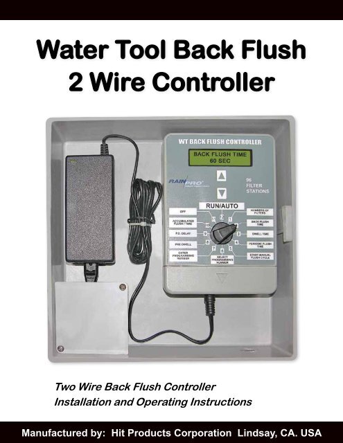
<strong>Water</strong> <strong>Tool</strong> <strong>Back</strong> <strong>Flush</strong><br />
2 <strong>Wire</strong> <strong>Controller</strong><br />
Two <strong>Wire</strong> <strong>Back</strong> <strong>Flush</strong> <strong>Controller</strong><br />
Installation and Operating Instructions<br />
Manufactured by: <strong>Hit</strong> <strong>Products</strong> <strong>Corporation</strong> Lindsay, CA. USA<br />
WWW.RAINPROCO.COM <strong>Water</strong> <strong>Tool</strong> <strong>Back</strong> <strong>Flush</strong> <strong>Controller</strong> 1
Table of ConTenTs<br />
Topic Page<br />
Specifications ............................................... 4<br />
Wiring Connection ......................................... 5<br />
Getting Started .............................................. 6<br />
Programming the <strong>Controller</strong> .......................... 6<br />
Decoder Programming .................................. 9<br />
Pressure Differential Switch ....................11-12<br />
Field Wiring ................................................. 13<br />
Master Valve ................................................ 14<br />
WT Decoder Field Wiring ............................. 15<br />
Two <strong>Wire</strong> Operation ..................................... 17<br />
Do’s & Don’ts .............................................. 18<br />
Battery/Solar Panel ..................................19-20<br />
Troubleshooting Hints ................................. 21<br />
WWW.RAINPROCO.COM <strong>Water</strong> <strong>Tool</strong> <strong>Back</strong> <strong>Flush</strong> <strong>Controller</strong> 3
<strong>Wire</strong> Type: Outdoor rated single or stranded copper connector<br />
<strong>Wire</strong> Size: Minimum 18 gauge<br />
<strong>Wire</strong> Runs: Maximum 500’<br />
Branching &<br />
Teeing: Yes<br />
DO NOT “Loop” the control wires back to the controller OR back onto themselves.<br />
DO NOT splice and direct bury wire connections/splices. All wire connections/splices<br />
should be made in valve boxes.<br />
<strong>Wire</strong> Connectors:<br />
Use the supplied LT-10 connectors, for Two <strong>Wire</strong> to Decoder Connection.<br />
Input Power: 100VAC-240VAC 50/60Hz<br />
4 <strong>Water</strong> <strong>Tool</strong> <strong>Back</strong> <strong>Flush</strong> <strong>Controller</strong><br />
sPeCIfICaTIons<br />
Filters Available 1-96<br />
<strong>Back</strong> <strong>Flush</strong> Time 15 seconds to 300 seconds in preset increments<br />
Dwell Time 15 seconds to 180 seconds in preset increments<br />
Period <strong>Flush</strong> Time 1 hour to 24 hours in preset increments<br />
Manual <strong>Flush</strong> Time Yes<br />
Accumulated <strong>Flush</strong> / Time Yes<br />
<strong>Flush</strong> Valves Per Decoder 1<br />
Pressure Differential Switch Capable Yes<br />
Field <strong>Wire</strong> Outputs Two <strong>Wire</strong> path may include branches and tees as<br />
necessary<br />
Minimum <strong>Wire</strong> Size 18 gauge<br />
Maximum <strong>Wire</strong> Run 500’<br />
Maximum Number of<br />
Decoders on system<br />
96<br />
Decoders<br />
Programmable and<br />
Re-Programmable to desired valve number<br />
Yes<br />
On Board Decoder<br />
Programming<br />
Capability at <strong>Controller</strong><br />
Yes<br />
Master Valve Capable Yes<br />
WWW.RAINPROCO.COM
Power<br />
Supply<br />
WIRInG ConneCTIons<br />
WT BACK FLUSH CONTROLLER<br />
WWW.RAINPROCO.COM <strong>Water</strong> <strong>Tool</strong> <strong>Back</strong> <strong>Flush</strong> <strong>Controller</strong> 5<br />
OFF<br />
ACCUMULATED<br />
FLUSH / TIME<br />
P.D. DELAY<br />
PRE DWELL<br />
ENTER<br />
PROGRAMMING<br />
NUMBER<br />
12V DC<br />
Power Input<br />
90-240VAC 50/60Hz<br />
®<br />
Intelligent Irrigation Solution<br />
RUN/AUTO<br />
10<br />
9<br />
8<br />
11 12<br />
SELECT<br />
PROGRAMMING<br />
NUMBER<br />
PRGM + LINE<br />
12V DC 12V DC<br />
OUT<br />
7<br />
6<br />
1<br />
5<br />
2<br />
4<br />
3<br />
Field <strong>Wire</strong>s<br />
To Tanks<br />
96<br />
FILTER<br />
STATIONS<br />
EXT R<br />
NUMBERS OF<br />
FILTERS<br />
BACK FLUSH<br />
TIME<br />
DWELL TIME<br />
PERIODIC FLUSH<br />
TIME<br />
START MANUAL<br />
FLUSH CYCLE<br />
PRESSURE<br />
SWITCH
1.<br />
2.<br />
3.<br />
4.<br />
5.<br />
6.<br />
7.<br />
Position 1<br />
Number of Filters<br />
Use the arrow buttons to select the number of filters 1 thru 96.<br />
Position 2<br />
<strong>Back</strong> <strong>Flush</strong> Time<br />
Use the arrow buttons to select the <strong>Back</strong> <strong>Flush</strong> Time of 15, 30, 45, 60, 75, 90,<br />
105, 120, 135, 150, 165, 180, 210, 240, 270 or 300 seconds.<br />
6 <strong>Water</strong> <strong>Tool</strong> <strong>Back</strong> <strong>Flush</strong> <strong>Controller</strong><br />
WT baCk flush GeTTInG<br />
sTaRTeD InsTRuCTIons<br />
With the power applied, turn the Dial to Position 1 Number of Filters. Use<br />
the Arrow Buttons to select the number of tanks in the system 1-96.<br />
Turn the Dial to Position 2. Use the Arrow Buttons to select the <strong>Back</strong> <strong>Flush</strong><br />
duration of each individual tank in 15 seconds increments from 15 seconds<br />
to 180 seconds and 30 second increments from 180 seconds to 300 seconds.<br />
Turn the Dial to Position 3. Use the Arrow Buttons to select the Dwell Time,<br />
between one individual tanks flushing cycle to end and the next tank to<br />
begin <strong>Back</strong> <strong>Flush</strong>ing. In preset increments from 15 seconds to 180 seconds.<br />
Turn the Dial to Position 4. Use the Arrow Buttons to select the Periodic<br />
<strong>Flush</strong> Time in one hour increments from 1 hour to 16 hours and 2 hours<br />
increments from 16 hours to 24 hours. This is for setting the frequency<br />
that the controller will initiate a complete <strong>Back</strong> <strong>Flush</strong> cycle of all the tanks<br />
in the system.<br />
To start a complete <strong>Back</strong> <strong>Flush</strong> cycle manually turn the Dial to Position 5<br />
and press either Arrow Button. To allow the controller to run automatically<br />
turn the Dial to Position 12 RUN / AUTO. The time remaining until the next<br />
cycle will be displayed.<br />
Position 10 will show how many <strong>Back</strong> <strong>Flush</strong> cycles accumulated during<br />
the time shown on the right side of the display. To reset, press the up<br />
Arrow Button.<br />
Set the Pre Dwell and Pressure Differential Delay Time if needed.<br />
PRoGRaMMInG The ConTRolleR<br />
WWW.RAINPROCO.COM
Position 3<br />
Dwell Time<br />
Use the arrow buttons to select Dwell Time of 15, 30, 45, 60, 75, 90, 105, 120,<br />
135, 150, 165 or 180 seconds.<br />
Position 4<br />
Periodic <strong>Flush</strong> Time<br />
Use the arrow buttons to select the Periodic <strong>Flush</strong> Time of 1, 2, 3, 4, 5, 6, 7, 8,<br />
9, 10, 11, 12, 13, 14, 15, 16, 18, 20, 22 or 24 hours.<br />
Position 5<br />
Start Manual <strong>Flush</strong> Cycle<br />
Use the UP arrow button to start a Manual <strong>Flush</strong> Cycle using the programmed<br />
information in Dial Positions 1, 2 and 3. Leave the Dial in this Position to<br />
complete the cycle. Turning the Dial will cancel the <strong>Back</strong> <strong>Flush</strong> cycle.<br />
Position 6 and 7<br />
Programming Decoders<br />
These positions are used to program the decoders for each filter. In Position 6<br />
select the number of the decoder that will be programmed. Turn the Dial<br />
to Position 7 and press the UP arrow button to program the decoder. Have<br />
the decoder red wires connected to PRGM terminals and the field wires<br />
disconnected.<br />
NOTE:<br />
See Programming Instructions on page 9.<br />
Position 8<br />
Pre Dwell<br />
Use the arrow buttons to select a Pre Dwell setting from 0-360 seconds in 10<br />
second increments. The Master Valve will stay activated during the Dwell Time<br />
selected in Dial Position 3. If no Master Valve is used, no Pre Dwell is required.<br />
Set the Pre Dwell time to 0.<br />
Position 9<br />
Pressure Differential Switch Delay<br />
Use the arrow buttons to select Pressure Differential Switch Delay of 0 to 360<br />
seconds in 10 second increments. This delay is the time the Pressure Differential<br />
Switch must remain closed before a <strong>Back</strong> <strong>Flush</strong> is initiated. If a Pressure<br />
Differential Switch is not used no delay is required. Set the Pressure Differential<br />
Delay to 0.<br />
WWW.RAINPROCO.COM <strong>Water</strong> <strong>Tool</strong> <strong>Back</strong> <strong>Flush</strong> <strong>Controller</strong> 7
Position 10<br />
Accumulated <strong>Flush</strong> / Times<br />
This position displays the accumulated flushes and time.<br />
NOTE:<br />
Use arrow buttons to clear the accumulated flushes and times.<br />
Position 11<br />
OFF<br />
Use the UP arrow buttons to turn the controller OFF and leave the Dial in<br />
Position 11 after the controller turns OFF.<br />
NOTE:<br />
Rotating the Dial out of Position 11 will turn on the controller.<br />
NOTE:<br />
A controller with a connected Pressure Differential Switch will activate a<br />
<strong>Back</strong> <strong>Flush</strong> cycle when the controller is OFF. No “Periodic” <strong>Back</strong> <strong>Flush</strong> cycles<br />
will be initiated.<br />
NOTE:<br />
The information selected in Dial Positions 1, 2, 3 and 4 will not be lost<br />
when the controller is turned OFF or during a power outage.<br />
Position 12<br />
Run / Auto<br />
This position displays the time remaining before the next <strong>Back</strong> <strong>Flush</strong> cycle<br />
and will display the tank number and the <strong>Flush</strong> / Dwell times during a <strong>Back</strong><br />
<strong>Flush</strong> cycle.<br />
NOTE:<br />
A flashing “*”, will be displayed if the controller has encountered a loss<br />
of power. Rotating the Dial to the OFF position and back will clear “*”.<br />
There is no need to press the arrow button at this time.<br />
NOTE:<br />
The controller will run automatically if the Dial is left in any other position<br />
than Run/Auto.<br />
NOTE:<br />
A flashing “C” indicates three consecutive <strong>Back</strong> <strong>Flush</strong>es. Rotate the Dial<br />
to clear.<br />
8 <strong>Water</strong> <strong>Tool</strong> <strong>Back</strong> <strong>Flush</strong> <strong>Controller</strong><br />
WWW.RAINPROCO.COM
DeCoDeR PRoGRaMMInG<br />
WT BACK FLUSH CONTROLLER<br />
OFF<br />
ACCUMULATED<br />
FLUSH / TIME<br />
ENTER<br />
PROGRAMMING<br />
NUMBER<br />
Red<br />
Decoder Solenoid<br />
P.D. DELAY<br />
PRE DWELL<br />
®<br />
Intelligent Irrigation Solution<br />
PRGM<br />
RUN/AUTO<br />
10<br />
9<br />
8<br />
11 12<br />
7<br />
SELECT<br />
PROGRAMMING<br />
NUMBER<br />
+ LINE<br />
12V DC 12V DC<br />
OUT<br />
96<br />
FILTER<br />
STATIONS<br />
NUMBERS OF<br />
FILTERS<br />
BACK FLUSH<br />
TIME<br />
DWELL TIME<br />
PERIODIC FLUSH<br />
TIME<br />
START MANUAL<br />
FLUSH CYCLE<br />
WWW.RAINPROCO.COM <strong>Water</strong> <strong>Tool</strong> <strong>Back</strong> <strong>Flush</strong> <strong>Controller</strong> 9<br />
6<br />
1<br />
5<br />
2<br />
4<br />
3<br />
Black<br />
EXT R<br />
PRESSURE<br />
SWITCH<br />
Red LED<br />
Located below the surface<br />
of Epoxy next to Black wires
1.<br />
2.<br />
3.<br />
4.<br />
5.<br />
6.<br />
7.<br />
8.<br />
9.<br />
10.<br />
11.<br />
WaTeR <strong>Tool</strong> baCk flush<br />
ConTRolleR DeCoDeR<br />
PRoGRaMMInG InsTRuCTIons<br />
Turn the Dial to Position 11, press the UP arrow button.<br />
This will turn the controller OFF.<br />
Disconnect field wires from “Line Out” terminal.<br />
Connect the red wires of the decoder to the “Program” terminal. The supplied<br />
alligator leads maybe used to assist in programming multiple decoders.<br />
Turn the Dial to Position 6 “Select Programming Number”.<br />
Use the arrow buttons to select the number of the connected decoder or MSTR<br />
if a Master Valve is required.<br />
Turn the Dial to Position 7 “Enter Programming Number” to be programmed.<br />
Use the UP arrow button to start the programming process. The display shows<br />
“Programming Station” and then, “Programming Complete”.<br />
Also the red led in the decoder will flash 3 times.<br />
Remove the red wires from the “Program” terminal.<br />
Install a “Decoder Number Identification Tag” on one of the red wires.<br />
Repeat steps 3-7 to program another decoder.<br />
Reconnect the field wires in Line Out when completed.<br />
NOTE:<br />
If a <strong>Back</strong> <strong>Flush</strong> cycle was interrupted to program a Decoder, when the Dial is<br />
returned to the “Run/Auto” position the “Periodic <strong>Flush</strong> Time” scheduled <strong>Back</strong><br />
<strong>Flush</strong> will start from the beginning.<br />
10 <strong>Water</strong> <strong>Tool</strong> <strong>Back</strong> <strong>Flush</strong> <strong>Controller</strong><br />
WWW.RAINPROCO.COM
PRessuRe DIffeRenTIal sWITCh<br />
1/4”<br />
TUBING<br />
TO HIGH PRESSURE<br />
CONNECTOR ON THE<br />
INLET<br />
HIGH<br />
PRESSURE<br />
PRGM + -<br />
12V DC 12V DC<br />
Pressure Differential switch<br />
The Pressure Differential Switch terminal is located on the bottom right of the <strong>Controller</strong><br />
board labeled Pressure Switch. A Pressure Differential Switch can be used to initiate a<br />
complete <strong>Back</strong> <strong>Flush</strong> cycle. When a Pressure Differential Switch is installed and a preset<br />
Pressure Differential is reached a <strong>Back</strong> <strong>Flush</strong> cycle will start.<br />
For adjustment see page 12.<br />
NOTE: To have Pressure Differential Switch be the exclusive initiator of a flush cycle, the controller<br />
must be in the “OFF” mode (this eliminates the Periodic <strong>Flush</strong> Time from initiating a flush cycle).<br />
To put the controller in the “OFF” mode;<br />
1. Turn Dial to Position 11, the “OFF” position.<br />
2. Push UP Arrow Button. Screen will go blank and now only the Pressure Differential Switch will<br />
initiate a flush cycle. The Number of filters, <strong>Back</strong> <strong>Flush</strong> Time and all Dwell Times input into<br />
controller will remain intact for each flush cycle initiated by the Pressure Differential Switch.<br />
3. Leave Dial in Position 11 (with blank display).<br />
NOTE: With the controller in Dial Position 12. Both the Periodic <strong>Flush</strong> Time and a connected<br />
Pressure Differential Switch will initiate a <strong>Back</strong> <strong>Flush</strong>.<br />
NOTE: Pressure Differential Dwell Time, Dial Position 9.<br />
EXT R PRESSURE<br />
SWITCH<br />
WWW.RAINPROCO.COM <strong>Water</strong> <strong>Tool</strong> <strong>Back</strong> <strong>Flush</strong> <strong>Controller</strong> 11<br />
LINE<br />
OUT<br />
PRESSURE<br />
DIFFERENTIAL<br />
SWITCH<br />
LOW<br />
PRESSURE<br />
COMMON AND<br />
NORMALLy<br />
OPEN CONTACTS<br />
1/4”<br />
TUBING<br />
TO LOW PRESSURE<br />
CONNECTOR ON THE<br />
OUTLET
PRessuRe DIffeRenTIal sWITCh<br />
MounTInG anD aDJusTMenT<br />
To mount the Pressure<br />
Differential Switch, place the<br />
switch on the valve and screw<br />
it on with screws (A) and (B)<br />
as shown in Figure A.<br />
12 <strong>Water</strong> <strong>Tool</strong> <strong>Back</strong> <strong>Flush</strong> <strong>Controller</strong><br />
C<br />
aDJusTInG<br />
Loosen screws (D) and (E) and align edge (C) for desired<br />
Pressure Differential as shown in Figure B.<br />
D<br />
Figure B<br />
MounTInG<br />
E<br />
A B<br />
Figure A<br />
WWW.RAINPROCO.COM
fIelD WIRInG<br />
WT BACK FLUSH CONTROLLER<br />
OFF<br />
ACCUMULATED<br />
FLUSH / TIME<br />
P.D. DELAY<br />
PRE DWELL<br />
ENTER<br />
PROGRAMMING<br />
NUMBER<br />
Intelligent Irrigation Solution<br />
PRGM<br />
®<br />
RUN/AUTO<br />
10<br />
9<br />
8<br />
11 12<br />
7<br />
6<br />
SELECT<br />
PROGRAMMING<br />
NUMBER<br />
96<br />
FILTER<br />
STATIONS<br />
NUMBERS OF<br />
FILTERS<br />
BACK FLUSH<br />
TIME<br />
DWELL TIME<br />
PERIODIC FLUSH<br />
TIME<br />
START MANUAL<br />
FLUSH CYCLE<br />
WWW.RAINPROCO.COM <strong>Water</strong> <strong>Tool</strong> <strong>Back</strong> <strong>Flush</strong> <strong>Controller</strong> 13<br />
1<br />
5<br />
+ LINE EXT R PRESSURE<br />
12V DC 12V DC<br />
OUT<br />
SWITCH<br />
2<br />
4<br />
3
14 <strong>Water</strong> <strong>Tool</strong> <strong>Back</strong> <strong>Flush</strong> <strong>Controller</strong><br />
MasTeR ValVe<br />
A Master Valve or a Pressure Sustaining Valve can be added to the Two <strong>Wire</strong><br />
path if required. Program the WTA-150 D or WTA-150 D/S Decoder as a Master.<br />
Pre Dwell is the selected Time between the activation of the Master Valve and<br />
the start of Tank 1 in a <strong>Back</strong> <strong>Flush</strong> cycle. This will allow sufficient pressure and<br />
flow for efficient <strong>Back</strong> <strong>Flush</strong>ing of the media filter.<br />
See Decoder Programming page 9.<br />
Refer to Pre Dwell settings page 7.<br />
WT BACK FLUSH CONTROLLER<br />
OFF<br />
ACCUMULATED<br />
FLUSH / TIME<br />
P.D. DELAY<br />
PRE DWELL<br />
ENTER<br />
PROGRAMMING<br />
NUMBER<br />
®<br />
Intelligent Irrigation Solution<br />
PRGM<br />
RUN/AUTO<br />
10<br />
9<br />
8<br />
11 12<br />
7<br />
6<br />
1<br />
5<br />
SELECT<br />
PROGRAMMING<br />
NUMBER<br />
2<br />
4<br />
3<br />
96<br />
FILTER<br />
STATIONS<br />
NUMBERS OF<br />
FILTERS<br />
BACK FLUSH<br />
TIME<br />
DWELL TIME<br />
PERIODIC FLUSH<br />
TIME<br />
START MANUAL<br />
FLUSH CYCLE<br />
+ LINE EXT R PRESSURE<br />
12V DC 12V DC<br />
OUT<br />
SWITCH<br />
Master<br />
Valve<br />
WWW.RAINPROCO.COM
Field <strong>Wire</strong>s<br />
WT DECODER FIELD WIRING<br />
WT DeCoDeR fIelD WIRInG<br />
Splice<br />
DB-SPL<br />
From <strong>Controller</strong><br />
Cap To Next Tank<br />
Red<br />
Black<br />
WWW.RAINPROCO.COM <strong>Water</strong> <strong>Tool</strong> <strong>Back</strong> <strong>Flush</strong> <strong>Controller</strong> 15
Manual flush leVeR oPeRaTIon<br />
The Manual/Auto Lever is used<br />
to activate the <strong>Back</strong> <strong>Flush</strong> Valve<br />
manually on each individual tank.<br />
Figure A shows the lever in the<br />
closed position. This is the<br />
position the lever must be in for<br />
the controller<br />
to start a Black <strong>Flush</strong>.<br />
It is also the position for normal<br />
filtration and when no active<br />
Manual <strong>Back</strong> <strong>Flush</strong>ing is desired.<br />
Red <strong>Wire</strong><br />
Red <strong>Wire</strong><br />
Manual/Auto<br />
Lever<br />
(In Manual Manual/Auto<br />
<strong>Back</strong> <strong>Flush</strong> Lever<br />
mode (In Manual<br />
position) <strong>Back</strong> <strong>Flush</strong><br />
mode<br />
position)<br />
Figure B<br />
16 <strong>Water</strong> <strong>Tool</strong> <strong>Back</strong> <strong>Flush</strong> <strong>Controller</strong><br />
Black <strong>Wire</strong><br />
Red <strong>Wire</strong><br />
Red <strong>Wire</strong><br />
Manual/Auto<br />
Lever<br />
(In Manual/ Manual/Auto<br />
Automatic Lever<br />
filtration (In Manual/<br />
position) Automatic<br />
filtration<br />
position)<br />
Solenoid<br />
Decoder<br />
Black <strong>Wire</strong><br />
Solenoid<br />
Decoder<br />
Figure A<br />
Black <strong>Wire</strong><br />
Solenoid<br />
Decoder<br />
Figure B shows the lever<br />
in the manual <strong>Back</strong> <strong>Flush</strong><br />
position.<br />
This lever must be returned<br />
to the position in Figure A<br />
to stop a Manual<br />
<strong>Back</strong> <strong>Flush</strong> and/or allow<br />
the controller to electrically<br />
initiate a <strong>Back</strong> <strong>Flush</strong>.<br />
Black <strong>Wire</strong><br />
Solenoid<br />
Decoder<br />
WWW.RAINPROCO.COM
TWo WIRe oPeRaTIon<br />
<strong>Controller</strong> Operation<br />
When the controller is activated by either “Auto” programming or a “Manual”<br />
Input, the encoded signal is supplied to the Line Out Terminals.<br />
Decoder Operations<br />
The Decoder operates as an electronically controlled switch. When the decoder<br />
recognizes the encoded signal that matches its programmed number, it then<br />
allows or “switches” power to the solenoid on the valve <strong>Back</strong> <strong>Flush</strong>ing the tanks.<br />
Line Short/Valve Short Codes<br />
The controller, through its current monitoring ability, can display two fault<br />
conditions: One being “Short Line” the second being “Valve Short.” These<br />
faults are triggered when current draw has exceeded a pre-set level.<br />
Note:<br />
No Output is sent to the field during the following conditions:<br />
“Short Line” will retry at the next flush time. Turning the Dial out of “Run”<br />
and back will clear the display. If the short has not been corrected the controller<br />
will go back into “Line Short.” This fault can be caused by shorted field wires<br />
or bad decoder.<br />
“Short Valve” will stay displayed during that specific tanks run time. The<br />
controller will monitor the program status and standard operation will resume<br />
when the next valve is activated. If the problem has not been corrected by<br />
the time the controller is scheduled to Run again the “Short Valve” will repeat<br />
for that specific valve until the short is repaired.<br />
No <strong>Back</strong> <strong>Flush</strong> will occur for that specific tanks run time but all valves that do not<br />
have a “short” condition will continue to flush as programmed. This fault can be<br />
caused by a bad solenoid.<br />
WWW.RAINPROCO.COM <strong>Water</strong> <strong>Tool</strong> <strong>Back</strong> <strong>Flush</strong> <strong>Controller</strong> 17
18 <strong>Water</strong> <strong>Tool</strong> <strong>Back</strong> <strong>Flush</strong> <strong>Controller</strong><br />
WaTeR <strong>Tool</strong> baCk flush<br />
ConTRolleR InsTallaTIon<br />
“Do’s & Don’Ts”<br />
For Warranty To Be Valid, Installation Must Comply To All Instructions Below:<br />
1.<br />
2.<br />
3.<br />
4.<br />
5.<br />
Use only <strong>Hit</strong> <strong>Back</strong> <strong>Flush</strong> Decoders (WTA-150D) and Solenoids (WT-160) or<br />
a Connected Decoder and Solenoid (WTA-150D/S)<br />
Branching and Teeing of the Two <strong>Wire</strong> path is permitted with the <strong>Water</strong><br />
<strong>Tool</strong> <strong>Back</strong> <strong>Flush</strong> <strong>Controller</strong> System. <strong>Wire</strong> splices should be well planned<br />
and minimized using only the DB-SPL splice kits.<br />
(Included with all Decoders).<br />
<strong>Wire</strong> Connections<br />
DO NOT install the <strong>Water</strong> <strong>Tool</strong> <strong>Back</strong> <strong>Flush</strong> <strong>Controller</strong>, its Decoders or any<br />
<strong>Water</strong> <strong>Tool</strong> <strong>Back</strong> <strong>Flush</strong> <strong>Controller</strong> Field <strong>Wire</strong> within 15 feet of any high<br />
voltage electrical panels, meters, pumps, equipment or controls.<br />
On multiple controller Installations DO NOT connect any control wires of<br />
one controller with those of a different <strong>Controller</strong>.<br />
DO NOT “loop” field wiring. Terminate the field wires at the last tank on<br />
that Two <strong>Wire</strong> path.<br />
WWW.RAINPROCO.COM
aTTeRy/solaR Panel PoWeR<br />
WT BACK FLUSH CONTROLLER<br />
OFF<br />
ACCUMULATED<br />
FLUSH / TIME<br />
P.D. DELAY<br />
PRE DWELL<br />
ENTER<br />
PROGRAMMING<br />
NUMBER<br />
Intelligent Irrigation Solution<br />
PRGM<br />
®<br />
RUN/AUTO<br />
10<br />
9<br />
8<br />
11 12<br />
7<br />
6<br />
SELECT<br />
PROGRAMMING<br />
NUMBER<br />
96<br />
FILTER<br />
STATIONS<br />
NUMBERS OF<br />
FILTERS<br />
BACK FLUSH<br />
TIME<br />
DWELL TIME<br />
PERIODIC FLUSH<br />
TIME<br />
START MANUAL<br />
FLUSH CYCLE<br />
WWW.RAINPROCO.COM <strong>Water</strong> <strong>Tool</strong> <strong>Back</strong> <strong>Flush</strong> <strong>Controller</strong> 19<br />
1<br />
5<br />
+ LINE EXT R PRESSURE<br />
12V DC 12V DC<br />
OUT<br />
SWITCH<br />
2<br />
4<br />
3<br />
1. Disconnect Power Supply From Plug-In Terminal.<br />
2. Connect <strong>Wire</strong> from 12V DC Battery or Solar Panel/<br />
Change <strong>Controller</strong> to Terminal Block.<br />
Note: Be Sure to Observe Polarity.<br />
Note: 12V DC Only.
aTTeRy/solaR Panel PoWeR<br />
Continued<br />
Solar Panel<br />
Mounting<br />
Pole<br />
12V Battery<br />
20 <strong>Water</strong> <strong>Tool</strong> <strong>Back</strong> <strong>Flush</strong> <strong>Controller</strong><br />
Charge<br />
<strong>Controller</strong><br />
(If used)<br />
+ 12V DC<br />
- 12V DC<br />
WT BACK FLUSH CONTROLLER<br />
OFF<br />
ACCUMULATED<br />
FLUSH / TIME<br />
P.D. DELAY<br />
PRE DWELL<br />
ENTER<br />
PROGRAMMING<br />
NUMBER<br />
®<br />
Intelligent Irrigation Solution<br />
PRGM<br />
+<br />
12V DC<br />
RUN/AUTO<br />
10<br />
9<br />
8<br />
11 12<br />
7<br />
SELECT<br />
PROGRAMMING<br />
NUMBER<br />
12V DC<br />
6<br />
1<br />
5<br />
2<br />
4<br />
LINE<br />
OUT<br />
3<br />
96<br />
FILTER<br />
STATIONS<br />
EXT R<br />
NUMBERS OF<br />
FILTERS<br />
BACK FLUSH<br />
TIME<br />
DWELL TIME<br />
PERIODIC FLUSH<br />
TIME<br />
START MANUAL<br />
FLUSH CYCLE<br />
PRESSURE<br />
SWITCH<br />
WWW.RAINPROCO.COM
TRoubleshooTInG hInTs foR<br />
WaTeR <strong>Tool</strong> baCk flush<br />
ConTRolleR TWo WIRe sysTeMs<br />
PRobleM soluTIon<br />
Display Blank. No Power. 1) Check: 110v or 220v supply<br />
and connections. Correct as<br />
needed.<br />
2) Check: 12V Power at the<br />
output of the Power Supply.<br />
<strong>Controller</strong> Displaying “Short Line”<br />
or Turning ON/OFF and<br />
“Clicking”.<br />
High Current Draw<br />
1) Short field wires.<br />
2) Field wires of one<br />
controller connected to field<br />
wires of a second controller.<br />
No Valves Activating. 1) <strong>Controller</strong> not activating.<br />
2) Field <strong>Wire</strong> Connection.<br />
1) Possible failed Decoder.<br />
2) Field wires shorted.<br />
1) Check the “Line Out” wire<br />
connections at the <strong>Controller</strong>.<br />
2) Failed <strong>Controller</strong> Replace<br />
Panel.<br />
1) Check Decoder <strong>Wire</strong> Connection.<br />
2) See Decoder Operation.<br />
Single Valve not Activating. 1) Bad wire connection.<br />
2) Failed Decoder.<br />
Multiple Valves not Activating. 1) Field wiring or connections. 1) Check wiring and connections<br />
between the last valve working<br />
and the first valve not working.<br />
<strong>Controller</strong> displaying reads “Valve<br />
Short” with a valve number.<br />
Display frozen, does not respond<br />
to rotating valve.<br />
Valves Turning ON/OFF during<br />
run time.<br />
High current draw during valve 1) Possible bad solenoid.<br />
run time.<br />
2) Possible bad decoders.<br />
Micro is locked. 1) Turn power off for a minute,<br />
then back on.<br />
Possible EMF interference. Check: <strong>Controller</strong>, Decoder and<br />
Field Wiring location in respect to<br />
any high voltage.<br />
Display shows flashing * Indicates loss of Power see<br />
Dial Position 10, page 8.<br />
WWW.RAINPROCO.COM <strong>Water</strong> <strong>Tool</strong> <strong>Back</strong> <strong>Flush</strong> <strong>Controller</strong> 21
22 <strong>Water</strong> <strong>Tool</strong> <strong>Back</strong> <strong>Flush</strong> <strong>Controller</strong><br />
noTes<br />
WWW.RAINPROCO.COM
noTes<br />
WWW.RAINPROCO.COM <strong>Water</strong> <strong>Tool</strong> <strong>Back</strong> <strong>Flush</strong> <strong>Controller</strong> 23
24 <strong>Water</strong> <strong>Tool</strong> <strong>Back</strong> <strong>Flush</strong> <strong>Controller</strong><br />
RAIN PRO<br />
Intelligent Irrigation Solutions TM<br />
556 S. Mirage Avenue<br />
P.O. BOX 929<br />
Lindsay, CA 93247<br />
For Technical Support: 800-468-0071 ext. 115<br />
© 2011 HIT PRODUCTS CORPORATION<br />
MADE IN THE USA<br />
6/14/2012 REV.<br />
®<br />
WWW.RAINPROCO.COM