move or add ceiling lights - Homebase
move or add ceiling lights - Homebase
move or add ceiling lights - Homebase

Create successful ePaper yourself
Turn your PDF publications into a flip-book with our unique Google optimized e-Paper software.
how to... <strong>move</strong> <strong>or</strong> <strong>add</strong> <strong>ceiling</strong> <strong>lights</strong><br />
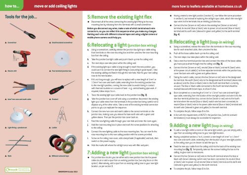
Tools f<strong>or</strong> the job...<br />
Screwdriver Small Insulated screwdriver<br />
Electric drill Four terminal junction box<br />
1mm2 two-c<strong>or</strong>e-and-earth cable<br />
Light fi tting – pendant set<br />
Bradawl<br />
L<strong>add</strong>er<br />
Nails<br />
Different coloured tape<br />
www.recyclenow.com<br />
Please recycle this fl yer<br />
HBHOWDO44 October 2010<br />
5: Re<strong>move</strong> the existing light fl ex<br />
<br />
Disconnect all of the wires connecting the existing light fitting to the rose<br />
mounting box by releasing from the terminals with a small screwdriver.<br />
Bef<strong>or</strong>e you disconnect any wires, make a note of which terminal each wire<br />
connects to, so you can refl ect this sequence when you make any changes.<br />
Marking each wire with different coloured tapes and using a digital camera <strong>or</strong><br />
mobile phone camera could help you.<br />
6: Relocating a light (junction box wiring)<br />
a. Using a screwdriver, carefully release the junction box light spur cable wiring<br />
from terminals on the rose mounting box and then unscrew the rose mounting<br />
box from the <strong>ceiling</strong>.<br />
b. Take the junction box light cable and push it back up into the <strong>ceiling</strong> void.<br />
c. The next steps now take place within the <strong>ceiling</strong> void.<br />
d. If the existing light spur cable is long enough to reach the new position, you<br />
could use it to connect the new light fitting to (assuming in good repair). Take<br />
the existing cabling and feed it through the new hole. Now fix your new <strong>ceiling</strong><br />
rose to the new location.<br />
e. If it’s not long enough, you will have to replace with a new length of 1mm2 <strong>or</strong><br />
1.5mm2 two-c<strong>or</strong>e-and-earth cable, extending from the existing junction box<br />
to the new light position, running the new cable to avoid it being in contact<br />
with thermal insulation <strong>or</strong> a source of heat – e.g. central heating pipe w<strong>or</strong>k. If<br />
required, follow steps f to m.<br />
f. Trace the existing light spur cable back to the junction box (fi g. 3).<br />
g. Take the junction box cover off and using a screwdriver disconnect the existing<br />
light spur cable wires from the terminals in the junction box being careful not to<br />
displace any of the other wires. Take a note of the existing terminal connection<br />
points so you can replicate the sequence.<br />
h. Connect the new two-c<strong>or</strong>e-and-earth cable to the c<strong>or</strong>rect terminals on the<br />
junction box, making sure you sleeve the bare earth wire with a green and<br />
yellow sleeve. Then put the junction box cover back on.<br />
i. Feed the new lighting cable through your new hole and enter the room again.<br />
j. Hold the rose mounting box in place and mark the screw positions f<strong>or</strong> attaching<br />
to the <strong>ceiling</strong>.<br />
k. Connect the new lighting cable to the rose mounting box. You can now fix the<br />
rose mounting box to the new <strong>ceiling</strong> position with the screws provided.<br />
l. Screw on the <strong>ceiling</strong> rose cover, <strong>add</strong> a lampshade (if applicable) and bulb, then<br />
switch on the power supply.<br />
m. Hide the marks left where the old light once was with filler and paint.<br />
7: Adding a new light (junction box wiring)<br />
<br />
F<strong>or</strong> junction box circuits you can either <strong>add</strong> a new junction box into the power<br />
cable circuit <strong>or</strong> <strong>add</strong> a spur from an existing junction box (we only focus on this<br />
option). Alternatively, <strong>add</strong> a spur from an existing <strong>ceiling</strong> rose to your new light<br />
location, as per section 9.<br />
<br />
<br />
m<strong>or</strong>e how to leafl ets available at homebase.co.uk<br />
Having created a new light position (section 4), now follow the same procedure<br />
in section 6, but instead of replacing the old light spur cable, attach the new light<br />
spur wires to the terminals into an existing junction box.<br />
Connect the live (brown <strong>or</strong> red) wire to the existing live (brown <strong>or</strong> red wire)<br />
terminal; its neutral (blue <strong>or</strong> black) wire to power circuit neutral (blue <strong>or</strong> black)<br />
terminal and its earth wire (sleeved in green and yellow) to the earth terminal<br />
(fi g. 4).<br />
8: Relocating a light (loop-in wiring)<br />
a. Using a screwdriver, release the wires from the terminals on the rose mounting<br />
box f<strong>or</strong> each attached cable, then unscrew the box.<br />
b. Push all the loose cables back up into the <strong>ceiling</strong> void.<br />
c. The next steps now take place within the <strong>ceiling</strong> void.<br />
d. Take a new four-terminal junction box and connect the wires of the loose cables<br />
you have just pushed through into the <strong>ceiling</strong> void (fi g. 3).<br />
e. Connect the live (brown <strong>or</strong> red), neutral (blue <strong>or</strong> black) and earth (bare) wires<br />
of the power circuit cable(s) to three separate terminals within the junction box,<br />
cover the bare wire with a green and yellow sleeve.<br />
f. Taking the switch cable, connect the live (brown <strong>or</strong> red) wire to the designated<br />
live terminal, the earth (bare) wire to the designated earth terminal (sleeve wire<br />
as above) and the (blue <strong>or</strong> black) wire to the fourth terminal that’s currently<br />
unused. The blue <strong>or</strong> black cable connected to the fourth terminal should be<br />
marked/sleeved with brown tape, to show it’s live.<br />
g. O nce completed run a new length of 1mm2 <strong>or</strong> 1.5mm2 two-c<strong>or</strong>e-and-earth light<br />
spur cable, extending from the location of the new light position and wire it into the<br />
new four-terminal junction box, connect its live (brown <strong>or</strong> red) wire to the fourth<br />
terminal where the neutral (blue <strong>or</strong> black) switch wire has been connected; its<br />
neutral (blue <strong>or</strong> black) wire to the power cable neutral (blue <strong>or</strong> black) terminal and<br />
its earth wire (sleeved in green and yellow) to the earth terminal.<br />
h. To complete the job, follow steps 6i to 6m.<br />
In line with the requirements of BS7671 the junction box, (with its screwed<br />
terminations) must always be accessible f<strong>or</strong> inspection.<br />
9: Adding a new light (loop-in wiring)<br />
<br />
To <strong>add</strong> a new light within a room on the same light switch, you can simply <strong>add</strong> a<br />
spur from an existing <strong>ceiling</strong> rose to your new light location.<br />
Having completed sections 2 to 4, connect a new length of 1mm2 <strong>or</strong> 1.5mm 2<br />
two-c<strong>or</strong>e-and-earth cable, extending from the location of your new light position<br />
to the <strong>ceiling</strong> rose you’ve chosen to <strong>add</strong> the spur to.<br />
<br />
<br />
<br />
Feed the new spur cable from the <strong>ceiling</strong> void into the back of the existing rose<br />
mounting box (fi g. 5). Temp<strong>or</strong>arily take out the screws holding the box to the<br />
<strong>ceiling</strong>, to give room to manoeuvre.<br />
Connect the live (brown <strong>or</strong> red) wire to the fourth terminal where the blue <strong>or</strong><br />
black with brown sleeving switch wire has been connected; its neutral (blue<br />
<strong>or</strong> black) wire to power circuit neutral (blue <strong>or</strong> black) terminal and its earth wire<br />
(sleeved in green and yellow) to the earth terminal.<br />
To complete the job, follow steps 6i to 6m.