Wire Rope Slings - Hanes Supply, Inc
Wire Rope Slings - Hanes Supply, Inc
Wire Rope Slings - Hanes Supply, Inc

You also want an ePaper? Increase the reach of your titles
YUMPU automatically turns print PDFs into web optimized ePapers that Google loves.
BRAID<br />
<strong>Wire</strong> <strong>Rope</strong> <strong>Slings</strong> ....................................2-12<br />
BRIDLE SLINGS<br />
2 legged ................................................2-7–9<br />
3 legged ....................................................2-9<br />
4 legged ..................................................2-10<br />
CABLE<br />
Laid Grommet Sling ................................2-11<br />
CRANE<br />
Hand Signals.............................................2-6<br />
GATOR-FLEX ® SLINGS ............................2-14<br />
GROMMET<br />
Cable Laid Sling ......................................2-11<br />
Strand Laid Sling.....................................2-11<br />
Gator-Flex ® ..............................................2-14<br />
LIFT ENGINEERING GUIDELINES<br />
Angles of Bridles .......................................2-1<br />
Basic Hitches ............................................2-1<br />
Calculating Load .......................................2-1<br />
Choker Hitch Rated Capacity<br />
Adjustment...............................................2-2<br />
D/d Ratios Apply to <strong>Slings</strong> .......................2-2<br />
Effect of Angles ........................................2-1<br />
Minimum Sling Body Length ....................2-2<br />
Sling Eye Design ......................................2-2<br />
LIFT RIGGERS GUIDE LINES<br />
Care of <strong>Wire</strong> <strong>Rope</strong> <strong>Slings</strong> .........................2-3<br />
Check List to Lift .......................................2-3<br />
Inspection..................................................2-3<br />
Planning a Lift .......................................2-4–5<br />
Turning or Repositioning to Load ..............2-5<br />
Sling Selection ..........................................2-2<br />
Sling Usage Dictates Sling Body<br />
Construction.............................................2-2<br />
Buffalo - Headquarters: 716.826.2636 FAX: 716.826.4412<br />
Albany/NE Division: 518.438.0139 FAX: 518.438.5343<br />
Rochester Division: 585.235.0160 FAX: 585.235.0229<br />
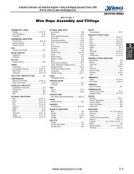
SECTION 2<br />
<strong>Wire</strong> <strong>Rope</strong> <strong>Slings</strong><br />
RIGGER GUIDELINE TO A LIFT<br />
Care of <strong>Wire</strong> <strong>Rope</strong> <strong>Slings</strong> .........................2-3<br />
Check List to Lift .......................................2-3<br />
Inspection..................................................2-3<br />
Planning a Lift .......................................2-4–5<br />
Turning or Repositioning to Load ..............2-5<br />
SIGNALS, CRANE HAND...........................2-6<br />
SLING MAX ® SLINGS .........................2-13–14<br />
SLINGS, WIRE ROPE<br />
Adjust-a-Leg............................................2-14<br />
Basket .......................................................2-8<br />
Braid-6 Part .............................................2-12<br />
Braid-8 Part .............................................2-12<br />
Bridle, 2-legged .....................................2-7–9<br />
Bridle, 3-legged .........................................2-9<br />
Bridle, 4-legged .......................................2-10<br />
Cable Laid ...............................................2-11<br />
Eye and Eye..............................................2-8<br />
Flemished Eyes...................................2-9–10<br />
Gator-Flex ® ..............................................2-14<br />
Grommet ........................................2-11, 2-14<br />
Hand Spliced Eyes....................................2-7<br />
Mechanically Spliced...........................2-8–10<br />
Round Body-4 part..................................2-13<br />
Single <strong>Rope</strong>...............................................2-7<br />
Slingmax ® <strong>Slings</strong> ...............................2-13–14<br />
Straid Laid ...............................................2-11<br />
Torpedo Lock (105B).................................2-8<br />
Tri Flex ® ...................................................2-13<br />
With Sliding Choker Hook .....................2-7–8<br />
STRAND<br />
Laid Sling ................................................2-11<br />
T & D ULTRA-FLEX SLINGS....................2-14<br />
TRI-FLEX ® SLINGS AND SYSTEM ..........2-13<br />
WWW.HANESSUPPLY.COM<br />
<strong>Hanes</strong> <strong>Supply</strong> of SC, <strong>Inc</strong>.<br />
CCISCO: 843.238.1338<br />
FAX: 843.238.8337<br />
SECTION INDEX<br />
WIRE ROPE, SLINGS<br />
Adjust-a-Leg............................................2-14<br />
Basket .......................................................2-8<br />
Braid-6 Part .............................................2-12<br />
Braid-8 Part .............................................2-12<br />
Bridle, 2-legged .....................................2-7–9<br />
Bridle, 3-legged .........................................2-9<br />
Bridle, 4-legged .......................................2-10<br />
Cable Laid ...............................................2-11<br />
Eye and Eye..............................................2-8<br />
Flemished Eyes...................................2-9–10<br />
Gator-Flex ® ..............................................2-14<br />
Grommet ........................................2-11, 2-14<br />
Hand Spliced Eyes....................................2-7<br />
Mechanically Spliced...........................2-8–10<br />
Round Body-4 part..................................2-13<br />
Single <strong>Rope</strong>...............................................2-7<br />
Slingmax ® ..........................................2-13–14<br />
Strand Laid..............................................2-11<br />
Torpedo Lock (105B).................................2-8<br />
Tri Flex ® ...................................................2-13<br />
With Sliding Choker Hook .....................2-7–8<br />
2-A<br />
2<br />
<strong>Wire</strong> <strong>Rope</strong><br />
<strong>Slings</strong>
2<br />
<strong>Wire</strong> <strong>Rope</strong><br />
<strong>Slings</strong><br />
NOTES<br />
2-B<br />
Buffalo - Headquarters: 716.826.2636 FAX: 716.826.4412<br />
Albany/NE Division: 518.438.0139 FAX: 518.438.5343<br />
Rochester Division: 585.235.0160 FAX: 585.235.0229<br />
WWW.HANESSUPPLY.COM<br />
<strong>Hanes</strong> <strong>Supply</strong> of SC, <strong>Inc</strong>.<br />
CCISCO: 843.238.1338<br />
FAX: 843.238.8337
Every Lift Uses 1 of 3 Basic<br />
Hitches<br />
STRAIGHT, or vertical, attachment is simply<br />
using a sling to connect a lifting hook to a load.<br />
Full rated lifting capacity of the sling may be utilized,<br />
but must not be exceeded. Whenever a<br />
single sling is used in this manner, a tagline<br />
should be used to prevent load rotation which<br />
may cause damage to the sling.<br />
When two or more slings are attached to the<br />
same lifting hook in straight, or vertical, manner,<br />
the total hitch becomes, in effect, a lifting bridle,<br />
and the load is distributed equally among the<br />
individual slings.<br />
CHOKER hitches reduce lifting capability of a<br />
sling, since this method of rigging affects ability<br />
of the wire rope components to adjust during<br />
the lift. A choker is used when the load will not<br />
be seriously damaged by the sling body – or the<br />
sling damaged by the load, and when the lift<br />
requires the sling to snug up against the load.<br />
The diameter of the bend where the sling<br />
contacts the load should keep the point of<br />
choke against the sling BODY – never against a<br />
splice or the base of the eye. When a choke is<br />
used at an angle of less than 135 degrees, the<br />
sling rated capacity must be adjusted downward<br />
to compensate for further loss of capability.<br />
A choker hitch should be pulled tight before a<br />
lift is made – NOT PULLED DOWN DURING<br />
THE LIFT. It is also dangerous to use only one<br />
choker hitch to lift a load which might shift or<br />
slide out of the choke.<br />
BASKET hitches distribute a load equally<br />
between the two legs of a sling – within limitations<br />
described below. Capacity of a sling used<br />
in a basket is affected by the bend, or curvature,<br />
where the sling body comes in contact with the<br />
load – just as any wire rope is affected and limited<br />
by bending action, as over a sheave.<br />
Calculating the Load on<br />
Each Leg of a Sling<br />
As the included angle between the legs of a<br />
sling increases, the load on each leg increases.<br />
The effect is the same whether a single sling is<br />
used as a basket, or two slings are used with<br />
each in a straight pull, as with a 2-legged bridle.<br />
Anytime pull is exerted at an angle on a leg -<br />
or legs - of a sling, the load per leg can be<br />
determined by using the data in the table shown<br />
on this page. Proceed as follows to calculate<br />
this load - and determine the rated capacity<br />
required of the sling, or slings, needed for a lift.<br />
1. First, divide the total load to be lifted by the<br />
number of legs to be used. This provides the<br />
load per leg if the lift were being made with<br />
all legs lifting vertically.<br />
2. Determine the angle between the legs of the<br />
Buffalo - Headquarters: 716.826.2636 FAX: 716.826.4412<br />
Albany/NE Division: 518.438.0139 FAX: 518.438.5343<br />
Rochester Division: 585.235.0160 FAX: 585.235.0229<br />
Lift Engineering Guidelines<br />
sling. When 3 or more legs are used, the<br />
angle will be TWICE the angle between one<br />
leg and an imaginary line extending straight<br />
down from the lifting hook.<br />
3. Then MULTIPLY the load per leg (as computed<br />
in No. 1) by the Load Factor for the leg<br />
angle being used (from the table at right) -<br />
to compute the ACTUAL LOAD on each leg<br />
for this lift and angle. THE ACTUAL LOAD<br />
MUST NOT EXCEED THE RATED SLING<br />
CAPACITY.<br />
Thus, in drawing three (sling angle at 60 O ):<br />
1000 . –. 2 = 500 (Load Per Leg if a vertical lift)<br />
500 x 1.154 = 577 lbs. = ACTUAL LOAD on<br />
each leg at the 60 O included angle being used.<br />
In drawing four (sling angle of 90 O ):<br />
1000 . –. 2 = 500 (Load Per Leg if a vertical lift)<br />
500 x 1.414 = 707 lbs. = ACTUAL LOAD on<br />
each leg at the 90 O included angle being used.<br />
Angles of Bridles<br />
The leg angles of bridles with 3 or more legs<br />
must be measured differently than the angles of<br />
2-legged hitches. First, establish a vertical line<br />
downward from the lifting hook as it would be<br />
positioned at the start of the lift. Measure the<br />
greatest angle between this line and any one<br />
leg. Multiplying this angle (known technically as<br />
the “half included angle”) by TWO yields the leg<br />
angle which is used to calculate the ACTUAL<br />
Load on each leg of the bridle.<br />
Leg Load<br />
Angle<br />
(degrees)<br />
Factor<br />
0 1.000<br />
10 1.003<br />
20 1.015<br />
30 1.035<br />
40 1.064<br />
50 1.103<br />
60 1.154<br />
70 1.220<br />
80 1.305<br />
90 1.414<br />
100 1.555<br />
110 1.743<br />
120 2.000<br />
Effect of Angles<br />
Various sling manufacturers refer in their specification<br />
tables to leg angles of slings during lifts -<br />
since these angles have a direct relationship to<br />
lifting capability of a sling. Regardless of how<br />
the sling angle may be stated, or the method<br />
used to compute stress in a sling leg, the load<br />
rating–or Rated Capacity–of the sling is the<br />
same. Capacity does not change–but stresses<br />
on sling legs change with rigging angles.<br />
Much misunderstanding results because the<br />
carrying capacity of a sling leg is reduced by<br />
the rigging angle. What happens is that the<br />
operator is lifting the load straight up (vertical)<br />
while the sling legs are pulling at an angle,<br />
thereby causing a disadvantage.<br />
WWW.HANESSUPPLY.COM<br />
<strong>Hanes</strong> <strong>Supply</strong> of SC, <strong>Inc</strong>.<br />
CCISCO: 843.238.1338<br />
FAX: 843.238.8337<br />
<strong>Wire</strong> <strong>Rope</strong> <strong>Slings</strong><br />
For quick figuring in the shop, a 30 degree<br />
leg angle (measured between one sling leg and<br />
a plumb line suspended from the hook) causes<br />
a loss in lifting capacity of 15%. A 45 degree<br />
angle reduces capacity by 30%... and a 60<br />
degree angle, 50%. This rule of thumb is not<br />
100% accurate, but is easy to remember and<br />
slightly on the safe side.<br />
It is always good practice, within limits, to<br />
keep the sling leg angle (“included” or “half<br />
included”, as illustrated) as small as possible.<br />
The length and width of the load sling length,<br />
and available headroom are determining factors<br />
in this sling angle.<br />
It is neither economical nor good practice to<br />
exceed a 60-degree sling leg angle. Angles<br />
greater than 60 degrees not only build up tension<br />
in the sling legs out of all proportion to the<br />
weight of the load, they also create a much<br />
greater “in-pull” on the ends of the load. This<br />
produces an eccentrically loaded column effect,<br />
as an engineer would describe it - meaning simply<br />
that long, slender objects have a tendency<br />
to buckle. Angles greater than 60 degrees indicate<br />
some thought should be given to the use of<br />
a lifting beam or other device in connection with<br />
the lift.<br />
Studying typical sling charts readily reveals<br />
that lifting capacities on slings are misleading<br />
unless the sling angle is stated. The same sling<br />
that will handle 10 tons at a 15-degree "included"<br />
leg angle will only handle 5 tons if this angle<br />
is increased to 60-degrees.<br />
Good Sling Practice<br />
Regardless what type of sling may be<br />
employed, there are accepted good working<br />
rules which will help increase useful sling life -<br />
as well as improve safety. These include:<br />
1. Use the proper sling for the lift. Whether single-part,<br />
multi-part, Braided or Cable Laid,<br />
the proper sling is the one with the best combination<br />
of work and handling features - of<br />
the proper length and rated capacity for the<br />
situation.<br />
2. Start and stop slowly. Crane hooks should be<br />
raised slowly until the sling becomes taut and<br />
the load is suspended. Lifting or lowering<br />
speed should be increased or decreased<br />
gradually. Sudden starts or stops place heavier<br />
loads on a sling - comparable to jamming<br />
the brakes on a speeding automobile. A rule<br />
of thumb: Shock loads can double the stress<br />
on a sling.<br />
3. If possible, set the load on blocks. Pulling a<br />
sling from under a load causes abrasion and<br />
“curling”–making the sling harder to handle<br />
on the next lift while reducing strength<br />
through loss of metal.<br />
4. Sharp corners cut slings. Use protector arcs,<br />
blocking, planks, and the like between sharp<br />
comers and the sling body.<br />
5. Store in a dry room. Moisture is a natural<br />
enemy of wire rope–as are acid fumes and<br />
other caustic gases.<br />
6. Avoid handling hot material or objects in<br />
direct contact with the sling. Strength goes<br />
down as temperature goes up!<br />
7. Dropping casting, tools or heavy objects on<br />
slings, or running over them with trucks, can<br />
cause damage. Always hang slings when not<br />
in use.<br />
8. Use hooks properly. “Point loading” reduces<br />
hook capacity. Pull should be straight in the<br />
line of lift.<br />
2-1<br />
2<br />
<strong>Wire</strong> <strong>Rope</strong><br />
<strong>Slings</strong>
2<br />
<strong>Wire</strong> <strong>Rope</strong><br />
<strong>Slings</strong><br />
<strong>Wire</strong> <strong>Rope</strong> <strong>Slings</strong><br />
Selecting a Sling<br />
The following is presented as a guide only to<br />
help in selection of a sling for a lift.<br />
1. Determine the Load: The weight of the load<br />
must be known. This is always the starting<br />
point.<br />
2. Decide the Hitch: Shape and bulk of the load<br />
must be accommodated as well as weight.<br />
Determine whether a straight attachment at<br />
some point on the load, a choker around the<br />
load, or some form of basket hitch will best<br />
control the load during the lift.<br />
3. Adequacy of Lifting Device: The lifting device<br />
must have adequate capacity for making the<br />
lift, and provide any maneuverability required<br />
once the load is hoisted.<br />
4. Room to Lift: Make certain the lifting device<br />
has sufficient headroom to raise the load to<br />
the height required. Headroom will affect the<br />
length of sling.<br />
5. Length of Sling: By applying your decision on<br />
the type of hitch to knowledge of the headroom<br />
offered by the lifting device, the length<br />
of sling can be calculated.<br />
6. Use Rated Capacity Chart: Always double<br />
check that the sling type and diameter you<br />
choose, when rigged at the angle determined<br />
by the length of the sling, or the specific type<br />
of hitch, will handle the load.<br />
Attaching the sling and completing the lift should<br />
be an orderly procedure without "surprises"<br />
when these steps have been followed. Two further<br />
precautions should be noted, however.<br />
First, plan to protect both load and sling from<br />
damage at sharp corners, etc. Wooden blocks<br />
and pads should be provided at the lift site. A<br />
protective pad should be used anytime a sling<br />
passes around a sharp corner.<br />
Last–but no means unimportant by being<br />
last–every sling should be visually examined<br />
from end to end BEFORE EVERY LIFT. It must<br />
be kept always in mind that the manufacturer’s<br />
Rated Capacity applies only to a new sling in<br />
“unused” condition. A sling should be carefully<br />
examined to determine that it is in as nearly<br />
new condition as practicable before each lift.<br />
There are specific standards on the use and<br />
care of slings in industries such as shipping and<br />
construction, and these provide some guidance<br />
for sling inspectors. Consensus standards published<br />
as ANSI B30.9 are particularly helpful.<br />
ANSI Standard B30.9 specifies that a wire<br />
rope sling should be removed from service any<br />
time any of the following conditions are detected:<br />
1. Ten randomly distributed broken wires in one<br />
rope lay, or five broken wires in one strand in<br />
one rope lay.<br />
2. Kinking, crushing, bird caging or any other<br />
damage resulting in distortion of the wire<br />
rope structure.<br />
3. Evidence of heat damage.<br />
4. End attachments that are cracked, deformed,<br />
or worn.<br />
5. Hooks that have been opened more than<br />
15% of the normal throat opening measured<br />
at the narrowest point, or twisted more than<br />
10 degrees from the plane of the unbent<br />
hook.<br />
6. Corrosion of the rope or end attachments.<br />
It is apparent from the foregoing that inspection<br />
of a wire rope sling to meet these removal criteria<br />
requires more than a casual understanding<br />
of wire rope design and manufacture, and the<br />
responsibility for daily inspections must be in the<br />
hands of trained personnel.<br />
2-2<br />
Buffalo - Headquarters: 716.826.2636 FAX: 716.826.4412<br />
Albany/NE Division: 518.438.0139 FAX: 518.438.5343<br />
Rochester Division: 585.235.0160 FAX: 585.235.0229<br />
Lift Engineering Guidelines<br />
Most of the foregoing applies equally to any<br />
type of sling and careful inspection by a trained<br />
inspector is necessary for safe sling use. If you<br />
require training for any type of sling inspection,<br />
<strong>Hanes</strong> <strong>Supply</strong> will provide you with the opportunity.<br />
Call for information regarding all of our educational<br />
courses in slings.<br />
Sling Eye Design<br />
Sling eyes are designed to provide what amount<br />
to “small inverted slings” at the<br />
ends of the sling body.<br />
Therefore, the width of the eye<br />
opening will be affected by the<br />
same general forces which<br />
apply to legs of a sling rigged<br />
as a basket.<br />
A sling eye should never be<br />
used over a hook or pin with a<br />
body diameter larger than the<br />
natural width of the eye. Never<br />
force an eye onto a hook.<br />
On the other hand, the eye should always be<br />
used on a hook or pin with at least the nominal<br />
diameter of the rope-since applying the D/d<br />
Ratio shows an efficiency loss of approximately<br />
50% when the relationship is less than 1/1.<br />
D/d Ratios Apply to <strong>Slings</strong><br />
When rigged as a basket, DIAMETER of the<br />
bend where a sling<br />
contacts the load can<br />
be a limiting factor on<br />
sling capacity.<br />
Standard D/d ratios -<br />
where “D” is the diameter<br />
of bend, and “d” the<br />
diameter of the rope<br />
are applied to determine<br />
efficiency of various<br />
sling constructions,<br />
as indicated below:<br />
Mechanically Spliced, Single Part <strong>Slings</strong>:<br />
25 times rope diameter.<br />
Hand Spliced, Single Part <strong>Slings</strong>:<br />
15 times rope diameter.<br />
Braided Multi-Part <strong>Slings</strong> of 6 Parts:<br />
25 times component rope diameter.<br />
Braided Multi-Part <strong>Slings</strong> of 8 Parts:<br />
25 times component rope diameter.<br />
Helically Laid Multi-Part <strong>Slings</strong>:<br />
25 times component rope diameter.<br />
Cable Laid <strong>Slings</strong>:<br />
10 times sling body diameter.<br />
Hand Tucked Grommets and Mechanically<br />
Joined Grommets: 5 times sling body diameter.*<br />
Sling Usage Dictates Sling<br />
Body Construction<br />
Whether to use a single-part sling... one made<br />
of a single wire rope in the sling body... or a<br />
multi-part sling (several ropes in the body) is<br />
usually the first decision to make after determining<br />
sling length and capacity for a lift.<br />
The starting point for this decision involves the<br />
handling characteristics of the sling more than<br />
any other factor. Based on capacity alone, multipart<br />
slings will be more flexible... more easily<br />
handled... than single-part slings. The larger the<br />
capacity of a sling, the more important this<br />
becomes... to the point it becomes unrealistic to<br />
build big capacity slings from single, very large<br />
wire ropes. Multi-part slings provide the only<br />
WWW.HANESSUPPLY.COM<br />
<strong>Hanes</strong> <strong>Supply</strong> of SC, <strong>Inc</strong>.<br />
CCISCO: 843.238.1338<br />
FAX: 843.238.8337<br />
practical means for obtaining extremely heavy lift<br />
capacity... in hundreds of tons.<br />
Various approaches to building multi-part<br />
slings have been developed; the most common<br />
of these are Braided and Cable Laid. These are<br />
described in detail elsewhere in this catalog.<br />
Braided or plaited, slings are often selected<br />
because this construction provides a gripping<br />
effect which reduces load slippage and rotation.<br />
In the design of a sling, rope engineers must<br />
seek a balance between strength, handling<br />
characteristics, and number of parts... since<br />
there is a tendency to lose strength as more<br />
parts are added to increase flexibility.<br />
Choker Hitch Rated<br />
Capacity Adjustment<br />
For wire rope slings in choker hitch when angle of<br />
choke is less than 120 O .<br />
Angle of choke Rated Capacity<br />
(Degrees) Percent*<br />
OVER-120 100<br />
90-120 87<br />
60-89 74<br />
30-59 62<br />
0-29 49<br />
*Percent of sling rated capacity in a choker hitch.<br />
If a load is hanging free, the normal choke<br />
angle is approximately 135 degrees. When the<br />
angle is less than 135 degrees an adjustment in<br />
the sling rated capacity must be made. Choker<br />
hitches at angles greater than 135 degrees are<br />
not recommended since they are unstable.<br />
Extreme care should be taken to determine the<br />
angle of choke as accurately as possible.<br />
In controlled tests, where the angle was less<br />
than 120 degrees, the sling body always failed<br />
at the point of choke when pulled to destruction.<br />
Allowance for this phenomenon must be made<br />
anytime a choker hitch is used to shift, turn or<br />
control a load, or when the pull is against the<br />
choke in a multi-leg lift.<br />
Minimum Sling Body<br />
Length<br />
This is the length of wire rope between splices,<br />
sleeves or fittings. Generally the minimum body<br />
length is equal to ten (10) times the sling body<br />
diameter. This allows approximately one and<br />
one half (1-1/2) rope lays between splices.<br />
For Multi-part slings the minimum body length<br />
between splices is equal to forty (40) times the<br />
component rope diameter.
Rigger’s Check List<br />
1. Analyze and Measure–Determine the total<br />
weight to be moved as well as exactly how far<br />
it is to move and how high it must be lifted.<br />
2. Determine the Hitch–Decide how the load is<br />
to be connected to the lifting hook and how<br />
the sling will grip, or be attached to, the load.<br />
3. Select the Sling–In addition to adequate<br />
Rated Capacity for the angles and hitch<br />
involved, the sling body should be of the type<br />
and style best suited to handling this specific<br />
load. Select a sling with proper end attachments<br />
or eye protection, as well as attachment<br />
hardware such as clevises.<br />
4. Inspect the Sling–Make a good visual check<br />
of the sling you select to determine if it is in<br />
good condition and capable of making the lift.<br />
Refer to prevailing OSHA and ANSI regulations<br />
for inspection criteria.<br />
5. Rig Up, Not Down–Always attach the sling to<br />
the load first, then attach it to the hook.<br />
6. Check Everything–Before attempting a lift,<br />
take a light strain on the rigging, checking to<br />
see that blocking, sling and load protection<br />
and all safety devices are in place.<br />
7. Stand Clear and Lift–Let the lifting device<br />
and rigging do the job–don't use brute<br />
strength to prevent swinging or movement.<br />
Use a tagline, or tether, to control any movement.<br />
Keep all hands and toes out from<br />
under the load when it is suspended.<br />
8. Don’t Jerk!–Lift slowly and with a steady<br />
application of power.<br />
9. Put It Away!–After you’ve completed the job,<br />
check the sling for any damage (If it’s damaged,<br />
red tag it immediately or advise the<br />
sling inspector.), then return it to the sling<br />
storage rack for safekeeping until next usage.<br />
Care of <strong>Wire</strong> <strong>Rope</strong> <strong>Slings</strong><br />
Care of <strong>Slings</strong><br />
The amount of care and proper maintenance a<br />
sling receives will go a long way in determining<br />
its service life. Following are guidelines which<br />
experience has shown helpful.<br />
Storage: Proper storage requires that slings<br />
be kept in an area where they will not be<br />
exposed to water, extreme heat, or corrosive<br />
fumes, liquids, and sprays, of being run over or<br />
kinked.<br />
<strong>Slings</strong> should never be left beneath loads or<br />
lying around where they may be damaged. All<br />
slings, when not in use, should be kept on a<br />
rack. Use of a rack minimizes accidental damage<br />
and allows easier monitoring of condition<br />
between regular inspections. A rack will also<br />
save time by allowing larger slings to be picked<br />
up and returned by crane, thereby reducing<br />
manhandling.<br />
Effects of Temperature<br />
All wire rope should be protected from extremes<br />
of temperature. The accepted rules are: Fiber<br />
core slings should never be exposed to temperature<br />
in excess of 200OF. Steel cored slings<br />
should never be used at temperatures above<br />
400OF. or below minus -60OF. It is not always easy to detect when wire rope<br />
has been damaged by heat. The most common<br />
visual signs are loss of lubrication and discoloration<br />
of wires.<br />
The best practice to follow is that if there is<br />
the slightest suspicion that a sling was subjected<br />
to high temperatures, it should be taken out<br />
of service immediately. If it is absolutely necessary<br />
to use slings outside of the above temperature<br />
range, the sling manufacturer should be<br />
consulted.<br />
Buffalo - Headquarters: 716.826.2636 FAX: 716.826.4412<br />
Albany/NE Division: 518.438.0139 FAX: 518.438.5343<br />
Rochester Division: 585.235.0160 FAX: 585.235.0229<br />
Rigger Guidelines<br />
Basic Inspection Criteria<br />
For <strong>Wire</strong> <strong>Rope</strong> <strong>Slings</strong><br />
The goal of a sling inspection is to evaluate<br />
remaining strength in a sling which has been<br />
used previously to determine if it is suitable for<br />
continued use.<br />
Specific inspection intervals and procedures<br />
are required by the Occupational Safety and<br />
Health Act (OSHA) and by ANSI B30.9<br />
Regulations, and the responsibility for performance<br />
of inspections is placed squarely upon the<br />
sling user by Federal Legislation.<br />
As a starting point, the same work practices<br />
which apply to all “working” wire ropes apply to<br />
wire rope which has been fabricated into a<br />
sling. Therefore, a good working knowledge of<br />
wire rope design and construction will be not<br />
only useful but essential in conducting a wire<br />
rope sling inspection.<br />
But because wire rope is a rather complex<br />
machine, no precise rules can be given to determine<br />
exactly when a wire rope sling should be<br />
replaced. There are many variables, and all<br />
must be considered.<br />
OSHA specifies that a wire rope sling shall be<br />
removed from service immediately if ANY of the<br />
following conditions are present:<br />
1. Broken <strong>Wire</strong>s: For single-part slings, 10 randomly<br />
distributed broken wires in one rope<br />
lay, or five broken wires in one strand of one<br />
rope lay. For multi-part slings these same criteria<br />
apply to each of the component ropes.<br />
For this inspection, a broken wire shall only<br />
be counted once; that is, each break should<br />
have two ends.<br />
2. Metal Loss: Wear or scraping of one-third<br />
the original diameter of outside individual<br />
wires. This is quite difficult to determine on<br />
slings and experience should be gained by<br />
the inspector by taking apart old slings and<br />
actually measuring wire diameters.<br />
3. Distortion: Kinking, crushing, birdcaging or<br />
other damage which distorts the rope structure.<br />
The main thing to look for is wires or<br />
strands that are pushed out of their original<br />
positions in the rope. Slight bends in a rope<br />
where wires or strands are still relatively in<br />
their original positions would not be considered<br />
serious damage. But good judgment is<br />
indicated.<br />
4. Heat Damage: Any metallic discoloration or<br />
loss of internal lubricant caused by exposure<br />
to heat.<br />
5. Bad End Attachments: Cracked, bent or<br />
broken end fittings caused by abuse, wear or<br />
accident.<br />
6. Bent Hooks: No more than 15 percent over<br />
the normal throat openings, measured at the<br />
narrowest point, or twisting of more than 10<br />
degrees is permissible.<br />
7. Metal Corrosion: Severe corrosion of the<br />
rope or end attachments which has caused<br />
pitting or binding of wires should be cause for<br />
replacing the sling. Light rusting usually does<br />
not affect strength of a sling, however.<br />
In addition to these seven conditions specified<br />
by OSHA, the following are also important:<br />
8. Pulled Eye Splices: Any evidence that eye<br />
splices have slipped, tucked strands have<br />
moved, or pressed sleeves show serious damage<br />
may be sufficient cause to reject a sling.<br />
9. Unbalance: A very common cause of damage<br />
is the kink which results from pulling<br />
through a loop while using a sling, thus causing<br />
wires and strands to be deformed and<br />
pushed out of their original position. This<br />
unbalances the sling, reducing its strength.<br />
Disposition of Retired <strong>Slings</strong>: the best inspection<br />
program available is of no value if slings which<br />
WWW.HANESSUPPLY.COM<br />
<strong>Hanes</strong> <strong>Supply</strong> of SC, <strong>Inc</strong>.<br />
CCISCO: 843.238.1338<br />
FAX: 843.238.8337<br />
<strong>Wire</strong> <strong>Rope</strong> <strong>Slings</strong><br />
are worn out and have been retired are not disposed<br />
of properly. When it is determined by the<br />
inspector that a sling is worn out or damaged<br />
beyond use, it should be tagged immediately<br />
DO NOT USE. This sling should then be<br />
destroyed as soon as possible by cutting the<br />
eye and fittings from the rope with a torch. This<br />
will help assure that an employee will not mistakenly<br />
use a sling which has been retired from<br />
service.<br />
It should also be obvious that a good inspection<br />
program will not only provide safer lifting<br />
conditions, but will also extend the life of slings<br />
and thereby reduce lifting costs.<br />
Federal Work Rules Require<br />
Specific Inspection Intervals<br />
Government regulations are also specific on<br />
WHEN to inspect.<br />
Both ANSI Standard B30.9 and OSHA require<br />
that wire rope slings receive two types of inspections:<br />
a DAILY visual inspection, and additional<br />
inspections where service conditions warrant.<br />
Daily visual inspections are intended to<br />
detect serious damage or deterioration which<br />
would weaken the sling. This inspection is usually<br />
performed by the person using the sling in a<br />
day-to-day job. He should look for obvious<br />
things, such as broken wires, kinks, crushing,<br />
broken attachments, severe corrosion, etc.<br />
Additional inspections should be performed at<br />
regular intervals based on, (1) frequency of sling<br />
use, (2) severity of service conditions, (3) nature<br />
of lifts, and (4) prior experience based on service<br />
life of slings used in similar circumstances.<br />
It is required that these additional inspections<br />
be carried out by a designated person who must<br />
have good knowledge of wire rope. An accurate<br />
WRITTEN and dated record of all conditions<br />
observed should be kept. Any deterioration of<br />
the sling which could result in appreciable, loss<br />
of original strength should be carefully noted,<br />
and determination made on whether further use<br />
would constitute a safety hazard.<br />
How to Inspect<br />
Precisely how to make proper, adequate inspections<br />
is not detailed by OSHA–yet it is in the<br />
HOW of inspection that the big difference<br />
between a good inspection and something less<br />
become apparent.<br />
Inspection should follow a systematic procedure:<br />
1. First, it is necessary that all parts of the sling<br />
are readily visible. The sling should be laid<br />
out so every part is accessible.<br />
2. Next, the sling should be sufficiently cleaned<br />
of dirt and grease so wires and fittings are<br />
easily seen. This can usually be accomplished<br />
with a wire brush or rags.<br />
3. The sling should then be given a thorough,<br />
systematic examination throughout its entire<br />
length, paying particular attention to sections<br />
showing the most wear.<br />
4. Special attention should also be paid to fittings<br />
and end attachments, and areas of the<br />
sling adjacent to these fittings.<br />
5. When the worst section of a sling has been<br />
located. this area should then be carefully<br />
checked against the OSHA criteria.<br />
6. Label or identify slings that are inspected.<br />
7. Keep records of inspections that include<br />
dates and corresponding conditions of slings.<br />
8. Dispose immediately of slings that are rejected.<br />
A knowledgeable inspector will also insist on<br />
proper storage for out-of-use slings–to make<br />
his job easier if not for the good of the slings.<br />
Inspections are much easier–and probably<br />
more thorough–when slings are available for<br />
inspection in an orderly arrangement, out of<br />
the weather, away from heat and dirt.<br />
2-3<br />
2<br />
<strong>Wire</strong> <strong>Rope</strong><br />
<strong>Slings</strong>
2<br />
<strong>Wire</strong> <strong>Rope</strong><br />
<strong>Slings</strong><br />
<strong>Wire</strong> <strong>Rope</strong> <strong>Slings</strong><br />
On the following pages are some useful tips to<br />
help the rigger do his job more efficiently and<br />
safely. Prevailing work rules and government<br />
regulations place full responsibility for proper<br />
performance upon the rigger, so it is his duty to<br />
be familiar with the condition and capability of all<br />
tools and equipment used, as well as techniques<br />
employed. One basic rule always<br />
applies: Always know... never guess.<br />
Each lift may be divided into three parts, providing<br />
a convenient plan for proceeding:<br />
1. The Lifting Device–Know its capability and<br />
limitations, and its condition. When was it last<br />
inspected? If in doubt about capacity, check<br />
the placard.<br />
2. The Hitch–Here is where the rigger can exercise<br />
ingenuity... but it’s also the easiest place<br />
to make a mistake. This book can help you<br />
decide which sling to use, and<br />
how to rig it properly.<br />
3. The Load–The weight<br />
must be known. But<br />
you must also protect<br />
the load from<br />
possible damage<br />
by the slings...<br />
and protect the<br />
slings from<br />
damage by<br />
Is the lifting device adequate?<br />
Check the placard on the crane or<br />
hoist, and then answer three questions:<br />
1. Is capacity adequate for this lift?<br />
2. Will it lift high enough?<br />
3. Is horizontal reach adequate?<br />
Check the hook and reeving.<br />
1 Are sheaves properly rigged? If multi-part<br />
reeving, will it support the load?<br />
2 Is the hook the right size so sling eye won't be<br />
distorted when put over the hook?<br />
3 Check for cracks in<br />
bowl of the hook,<br />
and for evidence<br />
of point loading or<br />
bending to one side<br />
of 15% or more.<br />
Before you select a sling for a specific lift, determine<br />
the most effective hitch to do the job, protect<br />
the load, and protect the sling. One of three<br />
basic hitches will usually do the job.<br />
The type of hitch you select may determine the<br />
type of sling body that will best do the job, as<br />
well as the length of sling that will be needed.<br />
Lifting height, overhead clearance and hook travel<br />
will affect choice of hitch and length of sling.<br />
2-4<br />
Buffalo - Headquarters: 716.826.2636 FAX: 716.826.4412<br />
Albany/NE Division: 518.438.0139 FAX: 518.438.5343<br />
Rochester Division: 585.235.0160 FAX: 585.235.0229<br />
Rigger Guidelines<br />
Choose a sling body type which will best support<br />
the load while providing adequate rated capacity.<br />
The proper choice will provide:<br />
1. Lifting capacity needed.<br />
2. Proper D/d Ratio.<br />
3. Handling characteristics<br />
needed<br />
for rigging.<br />
4. Minimal damage to<br />
the sling.<br />
5. Minimal damage to<br />
the load.<br />
Protect the sling during the lift with blocking<br />
or paddling at sharp corners or where<br />
the sling body would be bent severely.<br />
Use a spreader bar between legs of a sling to<br />
prevent excessive side pressure on the load by<br />
the sling during the lift.<br />
When attaching a sling to eye bolts, always pull<br />
on line with the bolt axis. When hitching to bolts<br />
screwed into or attached to a load, a side pull<br />
may break the bolts.<br />
Use a shackle in the sling eye during a choke to<br />
protect sling body against excessive distortion.<br />
Always put shackle pin through sling eye, rather<br />
than against the sling body–since sliding movement<br />
of sling body could rotate pin, causing it to<br />
come loose.<br />
A sliding hook choker is superior to a shackle or<br />
unprotected eye, since it provides a greater<br />
bending radius for the sling body.<br />
Use blocking or padding to protect hollow vesseis,<br />
loose bundles and fragile items from scuffing<br />
and bending. Remember that blocking<br />
becomes part of the lift, and must be added to<br />
total weight on the sling.<br />
WWW.HANESSUPPLY.COM<br />
<strong>Hanes</strong> <strong>Supply</strong> of SC, <strong>Inc</strong>.<br />
CCISCO: 843.238.1338<br />
FAX: 843.238.8337<br />
When lifting crates or wooden boxes with a basket<br />
hitch, be sure load can withstand side pressure<br />
as tension is applied to sling. Use spreader<br />
bars and corner protectors to prevent damage<br />
to contents.<br />
When lifting a bundled load with a single sling<br />
near the center of gravity, a choke is more effective<br />
than a basket hitch to prevent unbalance<br />
and slipping of the load in the sling.<br />
the load. Some riggers will use a double wrap around the<br />
load, for 360 o gripping of the load, to prevent<br />
slippage during the lift.<br />
You can reduce the angle of a choke with<br />
a wooden block, or blocks, between the hitch<br />
and the load. This also increases the angle<br />
between the two legs to improve sling efficiency.<br />
When rigging two or more straight slings as a<br />
bridle, select identical sling constructions of<br />
identical length–with identical previous loading<br />
experience. Normal stretch must be the same<br />
for paired slings to avoid overloading individual<br />
legs and unbalancing the load during the lift.<br />
Single-part hand-spliced slings must not be permitted<br />
to rotate when rigged in a straight, vertical<br />
hitch. Rotation can cause the splice to unlay<br />
and pull out, resulting in dropping of the load.<br />
WARNING<br />
Hand-spliced slings<br />
should not be used in<br />
lifts where the sling<br />
may rotate and cause<br />
the wire rope to unlay.
Anytime a load is lifted beyond arm’s reach with<br />
a single-part load line or straight eye-and-eye<br />
sling, use a tagline to prevent load rotation. If a<br />
wire rope is permitted to rotate, the strands may<br />
unlay and the rope’s capacity will be reduced.<br />
Two basket hitches can be rigged with two<br />
slings to provide better balance for long loads.<br />
Be sure that slings cannot slide toward one<br />
another along the load when the lift is made.<br />
Use an equalizing bar with double basket hitches<br />
to reduce tendency of slings to slide together,<br />
and to keep loads level. By adjusting the<br />
hook point and using a come-along or chain<br />
block to support the heavy end, the load can be<br />
kept level during the lift.<br />
<strong>Inc</strong>orrect<br />
Correct<br />
Proper Use of Cribbing<br />
To turn or reposition a load, either one or two<br />
lifting devices may be employed. Always use a<br />
choker hitch or a single-leg direct attachment.<br />
Never attempt to turn a load with a basket, since<br />
the load will slide in the hitch,<br />
against the sling body–<br />
resulting in damage to both<br />
the sling and the load, and<br />
possibly a dropped load.<br />
Buffalo - Headquarters: 716.826.2636 FAX: 716.826.4412<br />
Albany/NE Division: 518.438.0139 FAX: 518.438.5343<br />
Rochester Division: 585.235.0160 FAX: 585.235.0229<br />
Rigger Guidelines<br />
One Hook Load Turning<br />
To turn a load with one hook, attach the sling<br />
directly to the load ABOVE the Center of Gravity.<br />
The lifting hook must be able to move, or travel,<br />
in the direction of the turn to prevent sliding of<br />
the pivot edge of the load just as the load leaves<br />
the ground. It may be necessary to lift the load<br />
clear to reposition it after the turn is completed,<br />
and irregular shapes sometimes will require<br />
blocking for support during and after the turn.<br />
Two-hook turning is employed when it is desired<br />
to turn the load freely in the air. Main and auxiliary<br />
hoists of a crane can often be used, or two<br />
cranes can be used.<br />
To turn from side (A) to (B) in 1 & 2 above,<br />
attach on side (B) above the Center of Gravity<br />
and on side (D) at the Center of Gravity, then lift<br />
both hoists equally until load is suspended.<br />
Lower auxiliary until turn is completed; detach<br />
sling at (B) before lowering load completely.<br />
To turn from side (B) to (C) in 3 & 4 above, lift<br />
balanced load at (D) directly above the Center<br />
of Gravity; then attach auxiliary at (B) and lift to<br />
desired position. Lower both hooks simultaneously<br />
until side (C) is in desired position.<br />
Turning with double choker<br />
gives good control, with weight<br />
always applied against a tight<br />
sling body and no movement<br />
between sling and load. To rig,<br />
place both eyes on top of load,<br />
pointing opposite direction of<br />
turn. Body of sling is then<br />
passed under load, through<br />
both eyes and over lifting<br />
hook. Blocking should be used<br />
under load to protect sling and<br />
facilitate removal.<br />
Lifting unbalanced loads when exact length<br />
slings are not available can be accomplished by<br />
rigging a choke on the heavy end, as right.<br />
Length can be adjusted before weight applies,<br />
but once the load comes onto the sling, the<br />
hitch is locked in position for the lift.<br />
WWW.HANESSUPPLY.COM<br />
<strong>Hanes</strong> <strong>Supply</strong> of SC, <strong>Inc</strong>.<br />
CCISCO: 843.238.1338<br />
FAX: 843.238.8337<br />
<strong>Wire</strong> <strong>Rope</strong> <strong>Slings</strong><br />
Center of Gravity of a rectangular object with<br />
homogenious characteristics will usually be<br />
below the junction of lines drawn diagonally<br />
from opposite corners. When a rectangular<br />
object has weight concentrated at one end,<br />
Center of Gravity will be situated toward that<br />
end–away from the intersection of diagonal<br />
lines. To avoid an unbalanced lift, the lifting<br />
hook must be rigged directly above the<br />
Center of Gravity.<br />
To locate the approximate Center of Gravity of an<br />
irregularly shaped article, visualize it enclosed by<br />
a rectangle. Where diagonals from opposite corners<br />
intersect will usually provide a lift point near<br />
the Center of Gravity.<br />
Overturning a heavy object onto cribbing, using<br />
one lifting hook and chainblock. To upend the<br />
object, chainblock “A” and the sling “B” should<br />
exchange positions.<br />
Doglegs, Sets and Kinks<br />
Kink<br />
Dogleg<br />
Eye<br />
Deformation<br />
When a loop is “pulled through,” it forms a kink<br />
which permanently deforms a wire rope by<br />
freezing or locking wires and strands. This prevents<br />
them from sliding and adjusting, and<br />
reduces rope strength.<br />
A dogleg is a “set” which occurs when a wire<br />
rope sling is pulled down snug against a load.<br />
A dogleg usually can be “rolled back” or turned<br />
inside out, and usefulness of the sling restored,<br />
since strands can still adjust.<br />
Eye deformation is ordinarily not detrimental to<br />
sling strength as long as there are no broken<br />
wires or gross distortion of the lay of strands. An<br />
eye has two legs, so has adequate strength for<br />
the load the body can carry. A sling should be<br />
retired when distortion locks the strands or flattens<br />
the rope in the eye so strands cannot move<br />
and adjust.<br />
2-5<br />
2<br />
<strong>Wire</strong> <strong>Rope</strong><br />
<strong>Slings</strong>
2<br />
<strong>Wire</strong> <strong>Rope</strong><br />
<strong>Slings</strong><br />
<strong>Wire</strong> <strong>Rope</strong> <strong>Slings</strong><br />
Use Main Hoist. Tap<br />
fist on head; then<br />
use regular signals.<br />
Hoist. With forearm<br />
vertical, forefinger<br />
pointing up, move<br />
hand in small<br />
horizontal circle.<br />
Extend Boom (Telescoping<br />
Booms).<br />
Both fists in front of<br />
body with thumbs<br />
pointing outward.<br />
Extend Boom (Telescoping<br />
Boom). One<br />
Hand Signal. One fist<br />
in front of chest with<br />
thumb tapping chest.<br />
2-6<br />
Buffalo - Headquarters: 716.826.2636 FAX: 716.826.4412<br />
Albany/NE Division: 518.438.0139 FAX: 518.438.5343<br />
Rochester Division: 585.235.0160 FAX: 585.235.0229<br />
WWW.HANESSUPPLY.COM<br />
<strong>Hanes</strong> <strong>Supply</strong> of SC, <strong>Inc</strong>.<br />
CCISCO: 843.238.1338<br />
FAX: 843.238.8337<br />
USA Standard Crane Hand Signals<br />
Use Whipline<br />
(Auxiliary Hoist). Tap<br />
elbow with one hand,<br />
then use regular<br />
signals.<br />
Lower. With arm<br />
extended downward,<br />
forefinger pointing<br />
down, move hand in<br />
small horizontal circles.<br />
Retract Boom (Telescoping<br />
Booms). Both<br />
fists in front of body<br />
with thumbs pointing<br />
toward each other.<br />
Retract Boom (Telescoping<br />
Boom). One<br />
Hand Signal. One fist<br />
in front of chest,<br />
thumb pointing outward<br />
and heel of fist<br />
tapping chest.<br />
Raise Boom. Arm<br />
extended, fingers<br />
closed, thumb<br />
pointing upward.<br />
Raise the Boom and<br />
Lower the Load.<br />
With arm extended<br />
thumb pointing up,<br />
flex fingers in and<br />
out as long as load<br />
movement is desired.<br />
Stop. Arm extended,<br />
palm down, hold<br />
position rigidly.<br />
Move Slowly. Use one<br />
hand to give any<br />
motion signal and<br />
place other hand<br />
motionless in front of<br />
hand giving the motion<br />
signal. (Hoist slowly<br />
shown as example.)<br />
Lower Boom. Arm<br />
extended, fingers<br />
closed, thumb<br />
pointing downward.<br />
Lower the Boom and<br />
Raise the Load.<br />
With arm extended,<br />
thumb pointing<br />
down, flex fingers in<br />
and out as load<br />
movement is desired.<br />
Emergency Stop.<br />
Arm extended, palm<br />
down, move hand<br />
rapidly right and left.<br />
Dog Everything.<br />
Clasp hands in front<br />
of body.<br />
Travel. Arm extended<br />
forward, hand<br />
open and slightly<br />
raised, make pushing<br />
motion in direction<br />
of travel.<br />
Travel. (One Track).<br />
Lock the track on side<br />
indicated by raised fist.<br />
Travel opposite track in<br />
direction indicated by<br />
circular motion of other<br />
fist, rotated vertically in<br />
front of body. (For<br />
crawler cranes only).<br />
Bridge Travel. Arm<br />
extended forward,<br />
hand open and<br />
slightly raised, make<br />
pushing motion in<br />
direction of travel.<br />
Multiple Trolleys.<br />
Hold up one finger<br />
for block marked “1”<br />
and two fingers for<br />
block marked “2”.<br />
Regular signals<br />
follow.<br />
Swing. Am extended,<br />
point with finger in<br />
direction of swing of<br />
boom.<br />
Travel (Both Tracks).<br />
Use both fists in front<br />
of body, making a circular<br />
motion about<br />
each other, indicating<br />
direction of travel; forward<br />
or backward. (For<br />
crawler cranes only.)<br />
Additional Signals for Bridge Cranes<br />
Trolley Travel. Palm<br />
up, fingers closed,<br />
thumb pointing in<br />
direction of motion,<br />
jerk hand horizontally.<br />
Magnet Is<br />
Disconnected.<br />
Crane Operator<br />
spreads both hands<br />
apart palms up.
Buffalo - Headquarters: 716.826.2636 FAX: 716.826.4412<br />
Albany/NE Division: 518.438.0139 FAX: 518.438.5343<br />
Rochester Division: 585.235.0160 FAX: 585.235.0229<br />
Buffalo SlingTM Single-<strong>Rope</strong> Leg Tucked Splice Loop End <strong>Slings</strong><br />
No. 100B<br />
The end of a single wire rope is bent back along the<br />
rope to form the eye, and strands are hand-tucked<br />
into the body of the rope in what is called a tapered<br />
and concealed splice. This splice makes a sling that<br />
is easily pulled through narrow<br />
spaces; there are no rough ends to<br />
snag hands. <strong>Slings</strong> with rope bodies<br />
larger than 1-1/2" diameter are made<br />
only with Burnt End splices in which<br />
Single Part Body Hand Spliced <strong>Slings</strong><br />
6x37 FC 6x19 FC<br />
6x37 FC 6x19 FC<br />
Rated Capacities (Tons)<br />
Min. IPS <strong>Rope</strong> - Fiber Core IPS <strong>Rope</strong> - IWRC EIPS <strong>Rope</strong> - IWRC<br />
Dia. Length Loop Dim. Basket Hitch Basket Hitch Basket Hitch<br />
of (SL) of Single Single Single<br />
<strong>Rope</strong> Sling W L Choker Leg Choker Leg Choker Leg<br />
(in) (ft - in) (in) (in) Hitch Vertical 60 o 45 o 30 o Hitch Vertical 60 o 45 o 30 o Hitch Vertical 60 o 45 o 30 o<br />
3/8 2 - 6 3 6 0.85 1.1 1.9 1.6 1.1 0.92 1.2 2.1 1.7 1.2 1.1 1.3 2.3 1.8 1.3<br />
7/16 2 - 9 3-1/2 7 1.2 1.4 2.4 2.0 1.4 1.2 1.5 2.6 2.1 1.5 1.4 1.8 3.1 2.5 1.8<br />
1/2 3 4 8 1.5 1.8 3.1 2.5 1.8 1.6 2.0 3.5 2.8 2.0 1.9 2.3 4.0 3.3 2.3<br />
9/16 3 - 6 4-1/2 9 1.9 2.3 4.0 3.3 2.3 2.0 2.5 4.3 3.5 2.5 2.4 2.9 5.0 4.1 2.9<br />
5/8 4 5 10 2.3 2.8 4.8 4.0 2.8 2.5 3.0 5.2 4.2 3.0 2.9 3.5 6.1 4.9 3.5<br />
3/4 4 - 6 6 12 3.3 3.9 6.8 5.5 3.9 3.6 4.2 7.3 5.9 4.2 4.1 4.8 8.3 6.8 4.8<br />
7/8 5 - 6 7 14 4.5 5.2 9.0 7.4 5.2 4.8 5.5 9.5 7.8 5.5 5.6 6.4 11 9.0 6.4<br />
1 6 8 16 5.9 6.7 12 9.5 6.7 6.3 7.2 12 10 7.2 7.2 8.3 14 12 8.3<br />
1-1/8 6 - 6 9 18 7.4 8.4 15 12 8.4 7.9 9.0 16 13 9.0 9.1 10 17 14 10<br />
1-1/4 7 10 20 9.0 10 17 14 10 9.7 11 19 16 11 11 13 23 18 13<br />
1-3/8 7 - 6 11 22 11 12 21 17 12 12 13 23 18 13 13 15 26 21 15<br />
1-1/2 8 - 6 12 24 13 15 26 21 15 14 16 28 23 16 16 18 31 25 18<br />
1-5/8 9 13 26 15 17 29 24 17 16 18 31 25 18 18 21 36 30 21<br />
1-3/4 9 - 6 14 28 17 20 35 28 20 19 21 36 30 21 21 24 42 34 24<br />
2 11 16 32 22 26 45 37 26 24 28 48 40 28 28 32 55 45 32<br />
2-1/4 12 - 6 18 36 28 32 55 45 32 30 34 59 48 34 35 40 69 57 40<br />
2-1/2 14 20 40 34 39 68 55 39 37 42 73 59 42 42 48 83 68 48<br />
*** Eye Slip-Thru Thimble<br />
<strong>Rope</strong><br />
Dia.<br />
Rated<br />
Capacity<br />
Dim. (in) Dim. (in)<br />
(in) (Tons)* A B No. L W<br />
1/4 .38 2 4 W-2 4-1/8 2-1/8<br />
5/16 .60 2-1/2 5 W-2 4-1/8 2-1/8<br />
3/8 .85 3 6 W-2 4-1/8 2-1/8<br />
1/2 1.5 4 8 W-3 4-3/8 2-3/8<br />
5/8 2.3 5 10 W-4 6-5/8 3-3/8<br />
3/4 3.3 6 12 W4 6-5/8 3-3/8<br />
7/8 4.5 6-1/2 1 3 W-5 7-1/8 3-3/4<br />
1 5.9 7 14 W-5 7-1/8 3-3/4<br />
1-1/8 7.4 7-1/2 15 W-6 8-3/8 4-3/8<br />
1-1/4 9. 8 16 W-6 8-3/8 4-3/8<br />
1-3/8 11. 8-1/2 17 W-7 9-1/2 5<br />
1-1/2 13. 9 18 W-7 9-1/2 5<br />
*Rated Capacities Basket Hitch based on D/d Ratio of 15.<br />
***See Choker Hitch Rated Capacity Adjustment.<br />
Rated Cap. (Tons)* Alloy Oblong Link Hook<br />
<strong>Rope</strong><br />
Dia. WLL**<br />
(in) 60O 45O 30O D L W (Tons) E R<br />
1/4 .85 .70 .49 1/2 5 2-1/2 3-1/4 15/16 3-7/32<br />
5/16 1.3 1.1 .76 1/2 5 2-1/2 1 1-1/32 3-21/32<br />
3/8 1.9 1.9 1.1 1/2 5 2-1/2 1-1/2 1-1/16 4 -3/32<br />
7/16 2.5 2.0 1.4 5/8 6 3 1-1/2 1-1/16 4-3/32<br />
1/2 3.2 2.6 1.8 3/4 5-1/2 2-3/4 2 1-7/32 4-11/16<br />
9/16 4.0 3.2 2.3 3/4 5-1/2 2-3/4 3 1-1/2 5-3/4<br />
5/8 4.9 4.0 2.8 1 8 4 3 1-1/2 5-3/4<br />
3/4 6.8 5.5 3.9 1 8 4 5 1-7/8 7-3/8<br />
7/8 8.9 7.3 5.2 1 8 4 7-1/2 2-1/4 9-1/16<br />
1 12. 9.5 6.7 1-1/4 8-3/4 4-3/8 7-1/2 2-1/4 9-1/16<br />
1-1/8 15. 12. 8.4 1-1/4 8-3/4 4-3/8 10 2-1/2 10- 1/16<br />
1-1/4 18. 15. 10. 1-1/2 12 6 10 2-1/2 10-1/16<br />
1-3/8 22. 18. 12. 1-3/4 12 6 15 3-3/8 12-1/2<br />
1-1/2 25. 21. 15. 1-3/4 12 6 15 3-3/8 12-1/2<br />
1-5/8 30. 24. 17. 2 14 7 AH-22 3-3/8 12-1/2<br />
1-3/4 34. 28. 20. 2 14 7 AH-30 4 14-1/16<br />
2 44. 36. 26. 2-1/4 16 8 AH-37 4-1/4 18-3/16<br />
2-1/4 55. 45. 32. 2-1/2 16 8 AH-45 4-3/4 20-1/8<br />
ends of strands are left exposed and cut off with a<br />
torch. These may also be cut shorter and served, for<br />
smoothness. All have the same rated capacity, size<br />
for size.<br />
E-TH-E E-TH-HT ST-TH-HT<br />
*Rated Capacities Basket Hitch based on D/d Ratio of 15.<br />
Rated Capacities based on pin diameter no larger than natural eye width or less than the nominal sling diameter.<br />
Rated Capacities based on design factor of 5.<br />
Sling angles of less than 30 degrees shall not be used.<br />
**Working Load Limit.<br />
Length<br />
A A W<br />
B<br />
Length<br />
WWW.HANESSUPPLY.COM<br />
B<br />
Length<br />
L<br />
D<br />
W<br />
Safety Latches are<br />
available if required.<br />
L<br />
Length<br />
R E<br />
<strong>Hanes</strong> <strong>Supply</strong> of SC, <strong>Inc</strong>.<br />
CCISCO: 843.238.1338<br />
FAX: 843.238.8337<br />
<strong>Wire</strong> <strong>Rope</strong> <strong>Slings</strong><br />
6x37 FC 6x19 FC<br />
Hand Spliced Eye<br />
The tapered and concealed splice<br />
utilizes tension in the rope body to<br />
secure strands where they are tucked<br />
back into the rope. Needs no metal<br />
sleeve to assure firm anchoring.<br />
When “tapered and concealed,” ends<br />
of strands are tucked inward and<br />
concealed inside the rope.<br />
WARNING: Hand-spliced<br />
slings should not be used in<br />
lifts where the sling may<br />
rotate and cause the wire<br />
rope to unlay.<br />
Rated capacities of choker<br />
hitches apply when the<br />
angle of choke is greater<br />
than 120 O<br />
Rated capacities of basket<br />
hitches are based on a minimum<br />
diameter of curvature<br />
at the point of load contact of<br />
25 times the rope diameter.<br />
Rated Capacity (Tons)*<br />
2 Leg Alloy Alloy<br />
Choker Hitch***<br />
<strong>Rope</strong><br />
Dia.<br />
Oblong Link (in)<br />
(in) 600 450 300 D L W<br />
1/4 .66 .54 .38 1/2 5 2-1/2<br />
5/16 1.0 .84 .6 1/2 5 2-1/2<br />
3/8 1.5 1.2 .85 1/2 5 2-1/2<br />
7/16 2.0 1.6 1.2 5/8 6 3<br />
1/2 2.6 2.1 1.5 5/8 6 3<br />
9/16 3.3 2.7 1.9 3/4 5-1/2 2-3/4<br />
5/8 4.0 3.3 2.3 3/4 5-1/2 2-3/4<br />
3/4 5.8 4.7 3.3 1 8 4<br />
7/8 7.8 6.4 4.5 1 8 4<br />
1 10. 8.3 5.9 1 8 4<br />
1-1/8 13. 10. 7.4 1-1/4 8-3/4 4-3/8<br />
1-1/4 16. 13. 9. 1-1/2 12 6<br />
1-3/8 19. 15. 11. 1-1/2 12 6<br />
1-1/2 22. 18. 13. 1-3/4 12 6<br />
Length D<br />
W L<br />
* Rated Capacities Basket Hitch based on D/d<br />
Ratio of 15.<br />
*** See Choker Hitch Rated Capacity<br />
Adjustment.<br />
2-7<br />
2<br />
<strong>Wire</strong> <strong>Rope</strong><br />
<strong>Slings</strong>
2<br />
<strong>Wire</strong> <strong>Rope</strong><br />
<strong>Slings</strong><br />
Buffalo - Headquarters: 716.826.2636 FAX: 716.826.4412<br />
Albany/NE Division: 518.438.0139 FAX: 518.438.5343<br />
Rochester Division: 585.235.0160 FAX: 585.235.0229<br />
<strong>Wire</strong> <strong>Rope</strong> <strong>Slings</strong><br />
Buffalo SlingTM Single-<strong>Rope</strong> Legs Torpedo Loop-Lock <strong>Slings</strong><br />
No. 105B<br />
Eyes are formed using the flemish eye splice. Ends are secured<br />
by pressing a metal sleeve over the ends of the strands of the<br />
splice. Pull is directly along the centerline of rope and eye. Gives<br />
most efficient use of rope capacity and is economical.<br />
Flemish Eye Splice<br />
In the standard flemish eye mechanical<br />
splice, rope is separated into two<br />
parts–3 adjacent strands, and 3 adjacent<br />
strands and core. These two<br />
parts are then re-laid back in opposite<br />
directions to form an eye, and ends<br />
are secured with a pressed metal<br />
sleeve.<br />
Swaging Provides<br />
Positive Grip<br />
This cutaway of a metal sleeve swaged onto<br />
a splice shows how metal “flows” into valleys<br />
between strands to positively prevent<br />
ends from unlaying when sling is used within<br />
its rated capacity.<br />
Single-<strong>Rope</strong> Legs Torpedo Loop-Lock <strong>Slings</strong> & Choker Hooks<br />
*Rated capacities of Choker hitches apply when the angle of choke is<br />
greater than 135O Rated Capacity (Tons)* Sliding Choker<br />
Dia. IPS Slip-Thru Spliced Loops Hooks<br />
of <strong>Rope</strong> IPS EIPS Thimbles<br />
<strong>Rope</strong> Fiber <strong>Rope</strong> <strong>Rope</strong> Size Width Length Size Wt.<br />
(in) Core IWRC IWRC No. (in) (in) No. (lbs)<br />
1/4 .38 .42 .48 W-2 2 4 1/4 - 5/16 1.0<br />
3/8 .85 .93 1.1 W-2 3 6 3/8 0.8<br />
1/2 1.5 1.6 1.9 W-3 4 8 1/2 1.25<br />
5/8 2.3 2.5 2.9 W-4 5 10 5/8 2.5<br />
3/4 3.3 3.6 4.2 W-4 6 12 3/4 4.5<br />
7/8 4.5 4.9 5.7 W-5 7 14 7/8 - 1 10<br />
1 5.8 6.4 7.4 W-5 8 16 7/8 - 1 10<br />
1-1/8 7.1 7.8 9.0 W-6 9 18 1-1/8 - 1-1/4 26<br />
1-1/4 8.7 9.6 11 W-6 10 20 1-1/8 - 1-1/4 26<br />
1-3/8 10 11 13 W-7 11 22 1-3/8 - 1-1/2 42<br />
1-1/2 12 14 16 W-7 12 24 1-3/8 - 1-1/2 42<br />
.<br />
Two Leg Bridle <strong>Slings</strong><br />
No. 210B<br />
Single <strong>Rope</strong> Legs,<br />
Oblong Link,<br />
Sliding Choker<br />
Hooks and<br />
Torpedo<br />
Loop-Locks<br />
2-8<br />
Length of Sling (SL)<br />
Two Leg Basket <strong>Slings</strong><br />
No. 253C<br />
Two <strong>Rope</strong> Legs<br />
and Oblong Link<br />
with Torpedo<br />
Loop-Locks<br />
Length of Sling (SL)<br />
WWW.HANESSUPPLY.COM<br />
<strong>Hanes</strong> <strong>Supply</strong> of SC, <strong>Inc</strong>.<br />
CCISCO: 843.238.1338<br />
FAX: 843.238.8337<br />
Rated Capacities (Tons)*<br />
Min. Loop Dim.<br />
IPS <strong>Rope</strong> - IWRC EIPS <strong>Rope</strong> - IWRC<br />
Dia. Length Basket Hitch Basket Hitch<br />
of (SL) of Single Single<br />
<strong>Rope</strong> Sling W L Choker Leg Choker Leg<br />
(in) (ft - in) (in) (in) Hitch Vertical 60° 45° 30° Hitch Vertical 60° 45° 30°<br />
1/4 1 - 6 2 4 .41 .56 .97 .79 .56 .48 .65 1.1 .92 .65<br />
3/8 2 3 6 .93 1.2 2.1 1.7 1.2 1.1 1.4 2.4 2.0 1.4<br />
1/2 2 - 6 4 8 1.6 2.2 3.8 3.1 2.2 1.9 2.5 4.3 3.5 2.5<br />
5/8 3 5 10 2.5 3.4 5.9 4.8 3.4 2.9 3.9 6.8 5.5 3.9<br />
3/4 3 - 6 6 12 3.6 4.9 8.5 6.9 4.9 4.1 5.6 9.7 7.9 5.6<br />
7/8 4 7 14 4.8 6.6 11 9.3 6.6 5.6 7.6 13 11 7.6<br />
1 4 - 6 8 16 6.3 8.5 15 12 8.5 7.2 9.8 17 14 9.8<br />
1-1/8 5 9 18 7.9 10 17 14 10 9.1 12 21 17 12<br />
1-1/4 5 - 6 10 20 9.7 13 23 18 13 11 15 26 21 15<br />
1-3/8 6 11 22 12 15 26 21 15 13 18 31 25 18<br />
1-1/2 7 12 24 14 18 31 25 18 16 21 36 30 21<br />
1-3/4 8 14 28 19 25 43 35 25 21 28 48 40 28<br />
2 9 16 32 24 32 55 45 32 28 37 64 52 37<br />
2-1/4 10 18 36 30 39 68 55 39 35 44 76 62 44<br />
2-1/2 11 20 40 37 47 81 66 47 42 54 94 76 54<br />
2-3/4 12 22 44 44 57 99 81 57 51 65 113 92 65<br />
3 13 24 48 52 67 116 95 67 60 77 133 109 77<br />
3-1/2 16 - 6 32 64 69 88 152 124 88 79 102 177 144 102<br />
3-3/4 18 36 72 78 100 173 141 100 90 115 199 163 115<br />
4 20 40 80 88 113 196 160 113 101 130 225 184 130<br />
4-1/2 24 50 100 108 139 241 197 139 124 160 277 226 160<br />
* Rated capacities of basket hitches are based on a minimum diameter of curvature at the point<br />
of load contact of 40 times the rope diameter for slings 1/4" thru 1" diameter and 25 times the<br />
rope diameter for slings 1-1/4" diameter and larger.<br />
Length<br />
of<br />
Sling<br />
(SL)<br />
Slip-thru<br />
Thimble<br />
Sliding<br />
Choker<br />
Hook<br />
Slip-thru<br />
Thimble<br />
Sling #135 is similar to #136, but has a spliced<br />
loop on the load end in place of a thimble.<br />
Dia.<br />
of<br />
Rated Capacities* (Tons)<br />
IPS <strong>Rope</strong> IWRC** When Used<br />
Sliding****<br />
Choker Hooks<br />
Alloy<br />
Oblong<br />
<strong>Rope</strong> Size Wt. Links***<br />
(in) 60° 45° 30° (in) (lbs) d (in)<br />
3/8 1.6 1.3 0.93 3/8 .8 1/2<br />
1/2 2.8 2.3 1.6 1/2 1.25 3/4<br />
5/8 4.4 3.6 2.5 5/8 2.5 7/8<br />
3/4 6.3 5.1 3.6 3/4 4.5 1<br />
7/8 8.5 7.0 4.9 7/8 - 1 8 1-1/8<br />
1 11 9 6.4 7/8 - 1 8 1-1/2<br />
1-1/8 13 11 7.8 1-1/8 - 1-1/4 26 1-1/2<br />
1-1/4 17 14 9.6 1-1/8 - 1-1/4 26 1-3/4<br />
1-3/8 20 16 11 1-3/8 - 1-1/2 42 2<br />
1-1/2 24 19 14 1-3/8 - 1-1/2 42 2<br />
Dia.* Rated Capacities** Alloy<br />
of in tons when used Oblong<br />
<strong>Rope</strong> Links***<br />
(in) 60° 45° d (in)<br />
3/8 4.3 3.5 1<br />
1/2 7.6 6.2 1-1/2<br />
5/8 12 9.6 1-1/2<br />
3/4 17 14 2<br />
7/8 23 18 2<br />
1 29 24 2-1/4<br />
1-1/8 36 29 2-3/4<br />
1-1/4 44 36 2-3/4<br />
1-3/8 53 44 4<br />
1-1/2 63 52 4<br />
1-3/4 85 69 4<br />
2 110 90 4-3/4<br />
Length<br />
of<br />
Sling<br />
(SL)<br />
Thimble<br />
Sliding<br />
Choker<br />
Hook<br />
Length<br />
of<br />
Sling<br />
(SL)<br />
Sliding<br />
Choker<br />
Hook<br />
Length<br />
of<br />
Sling<br />
(SL)<br />
Sliding<br />
Choker<br />
Hook<br />
No. 135D No. 136D No. 137C No. 138C<br />
W<br />
Sling #138 is similar to #137, but has a thimble<br />
on the load end in place of a spliced loop.<br />
*Rated capacities are based on minimum<br />
diameter of curvature at the<br />
point of load contact of 20 times the<br />
rope diameter.<br />
**Information on EIPS ropes & fitting<br />
sizes with higher rated capacities is<br />
available on request.<br />
****Rated capacities of choker hitches<br />
apply when the angle of choke is<br />
greater than 135 0 .<br />
*Larger sizes are available on request.<br />
**Rated capacities are given in tons of 2000 lb. using IPS<br />
rope with IWRC. Information on EIPS ropes & fitting sizes<br />
with higher rated capacities is available on request. Rated<br />
capacities of basket hitches are based on minimum<br />
diamter of curvature at the point of loaded contact of 20<br />
times the rope diameter.<br />
L<br />
W<br />
L
Two-Leg Flemished Eye &<br />
Mechanically Swaged <strong>Slings</strong><br />
No. 200 Series<br />
Buffalo - Headquarters: 716.826.2636 FAX: 716.826.4412<br />
Albany/NE Division: 518.438.0139 FAX: 518.438.5343<br />
Rochester Division: 585.235.0160 FAX: 585.235.0229<br />
Dia. Min. Rated Capacities (Tons) Alloy Rated Capacities (Tons)<br />
of Length IPS-IWRC Oblong EIPS-IWRC<br />
<strong>Wire</strong> (SL) Of Links<br />
<strong>Rope</strong> Sling Dia.<br />
(in) Ft.- In. 60° 45° 30° (in) 60° 45° 30°<br />
1/4 1 - 3 .97 .79 .56 1/2 1.10 .91 .65<br />
5/16 1 - 6 1.50 1.30 .87 1/2 1.70 1.50 1.00<br />
3/8 1 - 8 2.10 1.80 1.20 3/4 2.50 2.00 1.40<br />
7/16 1 - 10 3.00 2.50 1.70 3/4 3.50 2.80 2.00<br />
1/2 2 - 0 3.80 3.10 2.20 3/4 4.40 3.60 2.50<br />
9/16 2 - 2 4.90 4.00 2.70 1 5.60 4.60 3.10<br />
5/8 2 - 4 5.90 4.80 3.40 1 6.80 5.50 3.90<br />
3/4 2 - 9 8.40 6.90 4.90 1-1/4 9.70 7.90 5.60<br />
7/8 3 - 3 11.00 9.30 6.60 1-1/4 13.00 11.00 7.60<br />
1 3 - 6 15.00 12.00 8.50 1-1/2 17.00 14.00 9.80<br />
1-1/8 4 - 0 18.00 15.00 10.00 1-3/4 21.00 17.00 12.00<br />
1-1/4 4 - 6 22.00 18.00 13.00 1-3/4 26.00 21.00 15.00<br />
1-3/8 5 - 0 27.00 22.00 15.00 2 31.00 25.00 18.00<br />
1-1/2 5 - 6 32.00 26.00 18.00 2-1/4 36.00 30.00 21.00<br />
1-5/8 6 - 0 38.00 31.00 20.00 2-1/2 43.00 35.00 23.00<br />
1-3/4 6 - 6 43.00 35.00 25.00 2-1/2 49.00 40.00 28.00<br />
2 8 - 0 55.00 45.00 32.00 2-3/4 63.00 52.00 37.00<br />
21/4 8 - 9 69.00 56.00 40.00 3-1/4 79.00 65.00 46.00<br />
2-1/2 10 - 0 84.00 68.00 48.00 3-3/4 97.00 79.00 56.00<br />
For approximate capacities using Fibre Core IPS: deduct 10% from<br />
IPS-IWRC strengths.<br />
For approximate capacities on Hand Braided <strong>Slings</strong>: deduct 15% from<br />
corresponding mechanically swaged strengths.<br />
For approximate capacities on Socket Attachments: add 5% to corresponding<br />
IWRC swaged strengths.<br />
Three-Leg Flemished Eye &<br />
Mechanically Swaged <strong>Slings</strong><br />
No. 300 Series<br />
<strong>Slings</strong> are 3-leg All-Purpose bridles, generally<br />
recommended for handling unbalanced loads.<br />
Dia. Min. Rated Capacities (Tons) Alloy Rated Capacities (Tons)<br />
of Length IPS-IWRC Oblong EIPS-IWRC<br />
<strong>Wire</strong> (SL) Of Links<br />
<strong>Rope</strong> Sling Dia.<br />
(in) Ft.- In. 60° 45° 30° (in) 60° 45° 30°<br />
1/4 1 - 3 1.40 1.20 .84 1/2 1.60 1.40 .97<br />
5/16 1 - 6 2.30 1.80 1.30 3/4 2.60 2.10 1.50<br />
3/8 1 - 8 3.20 2.60 1.90 3/4 3.70 3.00 2.20<br />
7/16 1 - 10 4.40 3.60 2.50 1 5.10 4.10 2.90<br />
1/2 2 - 0 5.70 4.60 3.30 1 6.60 5.30 3.80<br />
9/16 2 - 2 7.10 5.80 4.10 1 8.30 6.80 4.70<br />
5/8 2 - 4 8.80 7.20 5.10 1-1/4 10.00 8.30 5.90<br />
3/4 2 - 9 13.00 10.00 7.30 1-1/2 14.00 12.00 8.40<br />
7/8 3 - 3 17.00 14.00 9.90 1-1/2 20.00 16.00 11.00<br />
1 3 - 6 22.00 18.00 13.00 1-3/4 25.00 21.00 15.00<br />
1-1/8 4 - 0 27.00 22.00 16.00 2 31.00 25.00 18.00<br />
1-1/4 4 - 6 33.00 27.00 18.00 2-1/4 38.00 31.00 21.00<br />
1-3/8 5 - 0 40.00 33.00 22.00 2-3/4 46.00 38.00 25.00<br />
1-1/2 5 - 6 47.00 39.00 26.00 2-3/4 55.00 45.00 30.00<br />
1-5/8 6 - 0 53.00 43.00 31.00 2-3/4 61.00 49.00 36.00<br />
1-3/4 6 - 6 64.00 52.00 35.00 3 73.00 60.00 40.00<br />
2 8 - 0 83.00 67.00 46.00 3-1/2 95.00 76.00 53.00<br />
2-1/4 8 - 9 103.00 84.00 58.00 4 118.00 96.00 67.00<br />
2-1/2 10 - 0 126.00 102.00 72.00 4-1/2 145.00 118.00 84.00<br />
For approximate capacities using Fibre Core IPS: deduct 10% from IPS-<br />
IWRC strengths.<br />
For approximate capacities on Hand Braided <strong>Slings</strong>: deduct 15% from<br />
corresponding mechanically swaged strengths.<br />
For approximate capacities on Socket Attachments: add 5% to corresponding<br />
IWRC swaged strengths.<br />
WWW.HANESSUPPLY.COM<br />
<strong>Hanes</strong> <strong>Supply</strong> of SC, <strong>Inc</strong>.<br />
CCISCO: 843.238.1338<br />
FAX: 843.238.8337<br />
<strong>Wire</strong> <strong>Rope</strong> <strong>Slings</strong><br />
200FL<br />
2 leg–Oblong Link<br />
with Heavy Duty<br />
Thimbles on Top and<br />
Flemish Loops<br />
on Bottom.<br />
200HT<br />
2 leg–Oblong Link<br />
with Heavy Duty<br />
Thimbles on Top and<br />
Heavy Duty<br />
Thimbles on Bottom.<br />
200EH<br />
2 leg–Oblong Link<br />
with Heavy Duty<br />
Thimbles on Top and<br />
Eye Hoist Hooks<br />
Safety Latches on<br />
Bottom.<br />
200SPA<br />
2 leg–Oblong Link<br />
with Heavy Duty<br />
Thimbles on Top and<br />
Screw Pin Anchor<br />
Shackle on Bottom.<br />
300FL<br />
3 leg–Oblong Link<br />
with Heavy Duty<br />
Thimbles on Top and<br />
Flemish Loops on<br />
Bottom.<br />
300HT<br />
3 leg–Oblong Link<br />
with Heavy Duty<br />
Thimbles on Top and<br />
Heavy Duty<br />
Thimbles on Bottom.<br />
300EH<br />
3 leg–Oblong Link<br />
with Heavy Duty<br />
Thimbles on Top and<br />
Eye Hoist Hooks<br />
Safety Latches on<br />
Bottom.<br />
300SPA<br />
3 leg–Oblong Link<br />
with Heavy Duty<br />
Thimbles on Top and<br />
Screw Pin Anchor<br />
Shackle on Bottom.<br />
200CT<br />
2 leg–Oblong Link<br />
with Heavy Duty<br />
Thimbles on Top and<br />
Crescent Thimble on<br />
Bottom.<br />
200OS<br />
2 leg–Oblong Link<br />
with Heavy Duty<br />
Thimbles on Top and<br />
Open Swage Socket<br />
on Bottom.<br />
200CS<br />
2 leg–Oblong Link<br />
with Heavy Duty<br />
Thimbles on Top and<br />
Closed Swage<br />
Socket on Bottom.<br />
200BAS<br />
2 leg–Oblong Link<br />
with Heavy Duty<br />
Thimbles on Top and<br />
Bolt Anchor Shackle<br />
on Bottom.<br />
300CT<br />
3 leg–Oblong Link<br />
with Heavy Duty<br />
Thimbles on Top and<br />
Crescent Thimble on<br />
Bottom.<br />
300OS<br />
3 leg–Oblong Link<br />
with Heavy Duty<br />
Thimbles on Top and<br />
Open Swage Socket<br />
on Bottom.<br />
300CS<br />
3 leg–Oblong Link<br />
with Heavy Duty<br />
Thimbles on Top and<br />
Closed Swage<br />
Socket on<br />
Bottom.<br />
300BAS<br />
3 leg–Oblong Link<br />
with Heavy Duty<br />
Thimbles on Top and<br />
Bolt Anchor Shackle<br />
on Bottom.<br />
2-9<br />
2<br />
<strong>Wire</strong> <strong>Rope</strong><br />
<strong>Slings</strong>
2<br />
<strong>Wire</strong> <strong>Rope</strong><br />
<strong>Slings</strong><br />
<strong>Wire</strong> <strong>Rope</strong> <strong>Slings</strong><br />
Four-Leg Flemished Eye &<br />
Mechanically Swaged <strong>Slings</strong><br />
No. 400 Series<br />
2-10<br />
Buffalo - Headquarters: 716.826.2636 FAX: 716.826.4412<br />
Albany/NE Division: 518.438.0139 FAX: 518.438.5343<br />
Rochester Division: 585.235.0160 FAX: 585.235.0229<br />
<strong>Slings</strong> are 4-leg All-Purpose bridles, used both for balanced &<br />
unbalanced loads and for heavier loads where design calls for<br />
more distribution of weight by the use of attachment at four<br />
points.<br />
Dia. Min. Rated Capacities (Tons) Alloy Rated Capacities (Tons)<br />
of Length IPS-IWRC Oblong EIPS-IWRC<br />
<strong>Wire</strong> (SL) of Links<br />
<strong>Rope</strong> Sling Dia.<br />
(in) Ft.-In. 60° 45° 30° (in) 60° 45° 30°<br />
1/4 1 - 3 1.90 1.60 1.10 1/2 2.20 1.80 1.30<br />
5/16 1 - 6 3.00 2.50 1.70 3/4 3.50 2.80 2.00<br />
3/8 1 - 8 4.30 3.50 2.40 1 5.00 4.00 2.80<br />
7/16 1- 10 5.80 4.80 3.40 1 6.70 5.50 4.00<br />
1/2 2 - 0 7.60 6.20 4.40 1-1/4 8.70 7.10 5.00<br />
9/16 2 - 2 9.50 7.80 5.40 1-1/4 11.00 9.00 6.20<br />
5/8 2 - 4 12.00 9.60 6.80 1-1/4 13.00 11.00 7.80<br />
3/4 2 - 9 17.00 14.00 9.80 1-3/4 18.00 16.00 11.00<br />
7/8 3 - 3 23.00 18.00 13.00 1-3/4 26.00 21.00 15.00<br />
1 3 - 6 29.00 24.00 17.00 2-1/4 34.00 28.00 20.00<br />
1-1/8 4 - 0 36.00 29.00 20.00 2-3/4 42.00 34.00 24.00<br />
1-1/4 4 - 6 44.00 26.00 26.00 2-3/4 51.00 42.00 30.00<br />
1-3/8 5 - 0 53.00 44.00 30.00 3-1/4 61.00 50.00 36.00<br />
1-1/2 5 - 6 63.00 52.00 36.00 3-3/4 73.00 60.00 42.00<br />
1-5/8 6 - 0 74.00 61.00 40.00 3-3/4 85.00 70.00 46.00<br />
1-3/4 6 - 6 85.00 69.00 50.00 4-1/2 98.00 80.00 56.00<br />
2 8 - 0 110.00 90.00 64.00 4-1/2 126.00 104.00 74.00<br />
2-1/4 8 - 9 138.00 112.00 80.00 Call 158.00 130.00 92.00<br />
2-1/2 10 - 0 168.00 136.00 96.00 Call 194.00 158.00 112.00<br />
For approximate capacities using Fibre Core IPS: deduct 10% from IPS-<br />
IWRC strengths.<br />
For approximate capacities on Hand Braided <strong>Slings</strong>: deduct 15% from<br />
corresponding mechanically swaged strengths.<br />
For approximate capacities on Socket Attachments: add 5% to corresponding<br />
IWRC swaged strengths.<br />
WWW.HANESSUPPLY.COM<br />
<strong>Hanes</strong> <strong>Supply</strong> of SC, <strong>Inc</strong>.<br />
CCISCO: 843.238.1338<br />
FAX: 843.238.8337<br />
400FL<br />
4 leg–Oblong<br />
Link with Heavy<br />
Duty Thimbles<br />
on Top and<br />
Flemish Loops<br />
on Bottom.<br />
400HT<br />
4 leg–Oblong<br />
Link with Heavy<br />
Duty Thimbles<br />
on Top and<br />
Heavy Duty<br />
Thimbles on<br />
Bottom.<br />
400EH<br />
4 leg–Oblong<br />
Link with Heavy<br />
Duty Thimbles<br />
on Top and Eye<br />
Hoist Hooks<br />
Safety Latches<br />
on Bottom.<br />
400SPA<br />
4 leg–Oblong<br />
Link with Heavy<br />
Duty Thimbles<br />
on Top and<br />
Screw Pin<br />
Anchor Shackle<br />
on Bottom.<br />
Pertinent Dimensions for End Fittings for No. 200, 300 & 400 Series <strong>Slings</strong><br />
400CT<br />
4 leg–Oblong<br />
Link with Heavy<br />
Duty Thimbles<br />
on Top and<br />
Crescent<br />
Thimble on Bottom.<br />
400OS<br />
4 leg–Oblong<br />
Link with Heavy<br />
Duty Thimbles<br />
on Top and<br />
Open Swage<br />
Socket on Bottom.<br />
400CS<br />
4 leg–Oblong<br />
Link with Heavy<br />
Duty Thimbles<br />
on Top and<br />
Closed Swage<br />
Socket on<br />
Bottom.<br />
400BAS<br />
4 leg–Oblong<br />
Link with Heavy<br />
Duty Thimbles<br />
on Top and Bolt<br />
Anchor Shackle<br />
on Bottom.<br />
Diam. Standard Heavy Duty Alloy Carbon Half Thimble Open Closed<br />
Of Loop Inside Thimble Inside Hook Shackle Size (in) Inside Loop Swage Socket Swage Socket<br />
<strong>Wire</strong> Size-Tons Head<br />
<strong>Rope</strong> Width Length Width Length For For Width Lenth Pin. Jaw Hole. Thickness<br />
(in) (in) (in) (in) (in) IPS & EIPS<br />
6 x 19 with IWRC<br />
IPS EIPS (in) (in) Dia. (in) Opening (in) Dia. (in) (in)<br />
1/4 2 4 7/8 1-5/8 1 5/16 5/16 – – 11/16 11/16 3/4 1/2<br />
5/16 2-1/2 5 1-1/16 1-7/8 1 3/8 3/8 – – 13/16 13/16 7/8 11/16<br />
3/8 3 6 1-1/8 2-1/8 1-1/2 7/16 7/16 2 4 13/16 13/16 7/8 11/16<br />
7/16 3-1/2 7 1-1/4 2-3/8 2 1/2 1/2 2-1/4 5 1 1 1-1/16 7/8<br />
1/2 4 8 1-1/2 2-3/4 3 5/8 5/8 2-1/4 5-1/2 1 1 1-1/16 7/8<br />
9/16 4-1/2 9 1-1/2 2-3/4 5 5/8 5/8 2-1/4 5-1/2 1-3/16 1-1/4 1-1/4 1-1/8<br />
5/8 5 10 1-3/4 3-1/4 5 3/4 3/4 3-1/4 7 1-3/16 1-1/4 1-1/4 1-1/8<br />
3/4 6 12 2 3-3/4 7 7/8 7/8 3-1/4 9 1-3/8 1-1/2 1-7/16 1-5/16<br />
7/8 7 14 2-1/4 4-1/4 11 1 1 4-1/2 10-1/2 1-5/8 1-3/4 1-11/16 1-1/2<br />
1 8 16 2-1/2 4-1/2 11 1-1/8 1-1/4 4-1/2 12 2 2 2-1/16 1-3/4<br />
1-1/8 9 18 2-7/8 5-1/8 15<br />
6 x 37 with IWRC<br />
1-1/4 1-1/4 4-5/8 13-1/2 2-1/4 2-1/4 2-5/16 2<br />
1-1/4 10 20 2-7/8 5-1/8 15 1-3/8 1-1/2 5-1/2 15 2-1/2 2-1/2 2-9/16 2-1/4<br />
1-3/8 11 22 3-1/2 6-1/4 22 1-1/2 1-3/4 6 17 2-1/2 2-1/2 2-9/16 2-1/4<br />
1-1/2 12 24 3-1/2 6-1/4 22 1-3/4 1-3/4 6-1/2 18 2-3/4 3 2-13/16 2-1/2<br />
1-5/8 13 26 4 8 30 1-3/4 1-3/4 6-1/2 18 3-1/2 3-1/2 3-9/16 3<br />
1-3/4 14 28 4-1/2 9 30 1-3/4 2 7 21-1/2 3-1/2 3-1/2 3-9/16 3<br />
2 16 32 6 12 37 2 2-1/2 7 24-1/2 3-3/4 4 3-13/16 3-1/4<br />
2-1/4 18 36 7 14 45 2-1/2 2-1/2 8-1/2 25-1/2 4-1/4 4-1/4 4-5/16 4<br />
2-1/2 20 40 – – 60 2-1/2 3 8-1/2 26-1/2 4-1/4 4-1/4 4-5/16 4<br />
2-3/4 22 44 – – – 3 3 10 30 – – – –<br />
3 24 48 – – – 3 3 10 32 – – – –<br />
3-1/4 – 3 3-1/2<br />
3-1/2 – 3-1/2 3-1/2<br />
3-3/4 – 3-1/2 4<br />
4 – 4 4
Strand Laid Grommet<br />
<strong>Wire</strong> <strong>Rope</strong> <strong>Slings</strong><br />
Hand Tucked<br />
Continuous<br />
Construction... made<br />
from one continuous<br />
strand<br />
Buffalo - Headquarters: 716.826.2636 FAX: 716.826.4412<br />
Albany/NE Division: 518.438.0139 FAX: 518.438.5343<br />
Rochester Division: 585.235.0160 FAX: 585.235.0229<br />
Mechanical Splice Cable Laid Body<br />
<strong>Wire</strong> <strong>Rope</strong> <strong>Slings</strong><br />
Buffalo Sling TM No. 108C<br />
These smooth and very flexible slings are made from cut lengths of<br />
cable-laid fabric that is machine formed by laying six wire ropes in a helical<br />
pattern around a core rope. Flemish eye mechanical splices, secured<br />
by pressed metal sleeves, provide centerline pull at the eyes. More flexible<br />
than same capacity single-part slings.<br />
Ideal for use as basket or choker hitches, where flexibility and ease of<br />
handling are essential and cutting or abrasion is not a critical factor.<br />
Length<br />
Cable Laid Grommet <strong>Wire</strong> <strong>Rope</strong> <strong>Slings</strong><br />
No. 15B<br />
Strand Laid Grommets have either a wire<br />
rope body, or a body of six strands laid<br />
helically around a strand core, with either a<br />
hand tucked or a mechanical splice to form<br />
an endless sling body. Minimum circumference of the sling<br />
is 96 times the grommet body diameter.<br />
Mechanical Splice 7<br />
Parts of <strong>Wire</strong> <strong>Rope</strong> in<br />
the Sling Body<br />
When a choke is drawn down tight against a load, or a side pull is<br />
exerted resulting in an angle of less than 120 O , an adjustment must<br />
be made for further reduction of the sting rated capacity.<br />
Rated Capacities Basket Hitch and vertical lift based on D/d ratio of 5<br />
when "d" diameter of the finished grommet.<br />
Rated Capacities based on pin diameter no smaller than 5x the body dia.<br />
Rated capacities based on design factor of 5.<br />
Sling angles of less than 30 degrees shall not be used.<br />
*** See Lift Engineering Guidelines for Rated Capacity Adjustment for<br />
Choker Hitches.<br />
B<br />
A<br />
OT-OT<br />
HT-HT<br />
ST-ST<br />
E-E<br />
Cable Laid Grommets have six wire ropes<br />
laid helically around a wire rope core, with<br />
ends joined either by a hand tucked or a<br />
mechanical splice to form an endless body.<br />
Highly flexible, they resist kinks and are<br />
easy to handle. Minimum circumference of the sling is 96<br />
times the grommet body diameter.<br />
Hand Tucked<br />
Continuous<br />
Construction... made<br />
from one continuous<br />
strand<br />
Mechanical Splice<br />
Single-Part <strong>Wire</strong><br />
<strong>Rope</strong> Sling Body<br />
When a choke is drawn down tight against a load, or a side pull is<br />
exerted resulting in an angle of less than 120 O , an adjustment must<br />
be made for further reduction of the sling rated capacity.<br />
Rated Capacities Basket Hitch and vertical lift based on D/d ratio of 5<br />
when “d” diameter of the finished grommet.<br />
Rated Capacities based on pin diameter no smaller than 5x the body dia.<br />
Rated capacities based on design factor of 5.<br />
Sling angles of less than 30 degrees shall not be used.<br />
*** See Lift Engineering Guidelines for Rated Capacity Adjustment for<br />
Choker Hitches.<br />
No. 11B<br />
7x7x19 7x7x7<br />
Flemish Eye Splice<br />
In the standard flemish eye mechanical<br />
splice, the cable laid fabric is separated<br />
into two parts – 3 adjacent<br />
component ropes, and the other 3<br />
adjacent component ropes plus the<br />
core rope. These two parts are then<br />
re-laid back in opposite directions to<br />
form an eye, and ends are secured<br />
with a pressed metal sleeve.<br />
7 x19 and 7 x37 Class - IPS – Rated Cap. (Tons)<br />
Sling<br />
Body<br />
Basket Hitches<br />
Dia.<br />
(in) Vert.<br />
***<br />
Choker Vertical 600 450 300 1/4 .85 .60 1.7 1.5 1.2 .85<br />
5/16 1.3 .93 2.7 2.3 1.9 1.3<br />
3/8 1.9 1.3 3.8 3.3 2.7 1.9<br />
7/16 2.6 1.8 5.2 4.5 3.6 2.6<br />
1/2 3.3 2.3 6.7 5.8 4.7 3.3<br />
9/16 4.2 2.9 8.4 7.3 6.0 4.2<br />
5/8 5.2 3.6 10. 9.0 7.4 5.2<br />
3/4 7.4 5.2 15. 13. 10. 7.4<br />
7/8 10. 7.0 20. 17. 14. 10.<br />
1 13 9.1 26. 22. 18. 13.<br />
1-1/8 16. 11. 32. 28. 23. 16.<br />
1-1/4 20. 14. 39. 34. 28. 20.<br />
1-3/8 23. 16. 46. 40. 33. 23.<br />
1-1/2 27. 19. 54. 47. 38. 27.<br />
1-5/8 31. 22. 62. 54. 44. 31.<br />
1-3/4 36. 25. 72. 62. 51. 36.<br />
1-7/8 41. 28. 81. 70. 57. 41.<br />
2 46. 32. 92. 79. 65. 46.<br />
2-1/8 51. 36. 102. 88. 72. 51.<br />
2-1/4 56. 39. 113. 98. 80. 56.<br />
2-3/8 62. 44. 124. 108. 88. 62.<br />
2-1/2 68. 47. 136. 117. 96. 68.<br />
2-3/4 81. 56. 161. 140. 114. 81.<br />
3 94. 66. 189. 163. 133. 94.<br />
WWW.HANESSUPPLY.COM<br />
<strong>Hanes</strong> <strong>Supply</strong> of SC, <strong>Inc</strong>.<br />
CCISCO: 843.238.1338<br />
FAX: 843.238.8337<br />
<strong>Wire</strong> <strong>Rope</strong> <strong>Slings</strong><br />
Rated Capacity (Tons)*<br />
Basket Hitch Eye Slip<br />
Body * ** Thru Heavy Slip-on<br />
Dia. Vert. Choker Thimble Thimble Thimble<br />
(in) Hitch 60 0 45 0 30 0 A B ST HT QT<br />
1/4 .50 .34 1.0 .87 .71 .50 2 4 W-2 1/4 3/8<br />
3/8 1.1 .74 2.2 1.9 1.5 1.1 3 6 W-2 3/8 3/8<br />
1/2 1.9 1.3 3.7 3.2 2.6 1.9 4 8 W-3 1/2 1/2<br />
5/8 2.8 1.9 5.5 4.8 3.9 2.8 5 10 W-4 5/8 5/8<br />
3/4 4.1 2.8 8.1 7.0 5.8 4.1 6 12 W-4 3/4 3/4<br />
7/8 5.4 3.7 11. 9.4 7.6 5.4 7 14 W-5 7/8 7/8<br />
1 6.9 4.7 14. 12. 9.7 6.9 8 16 W-5 1 1<br />
1-1/8 8.3 5.8 17. 14. 12. 8.3 9 18 W-6 1-1/8 –<br />
1-1/4 9.9 7.0 20. 17. 14. 9.9 10 20 W-6 1-1/4 –<br />
* Rated Capacities Basket Hitch based on D/d ratio of 10 or greater.<br />
Rated Cap. based on pin diameter no larger than natural eye width or less than the nominal sling dia.<br />
Rated capacities based on design factor of 5.<br />
Sling angles of less than 30 degrees shall not be used.<br />
*** See Lift Engineering Guidelines for Rated Capacity Adjustment for Choker Hitches.<br />
Finished<br />
Sling<br />
Rated Capacity (Tons)<br />
Basket Hitches<br />
Body<br />
Dia. Vert.<br />
***<br />
Choker Vertical 300 450 600 7 x 7 x 19 Construction<br />
1/4 .83 .54 1.7 .83 1.2 1.4<br />
3/8 1.8 1.2 3.6 1.8 2.5 3.1<br />
1/2 3.0 2.0 6.1 3.0 4.3 5.3<br />
5/8 4.6 3.0 9.1 4.6 6.4 7.9<br />
7 x 6 x 19 and 7 x 6 x 37- EIP Construction<br />
3/4 6.2 4.1 12 6.2 8.8 11<br />
7/8 8.3 5.4 17 8.3 12 14<br />
1 11 6.8 21 11 15 18<br />
1-1/8 13 8.4 26 13 18 22<br />
1-1/4 16 10 31 16 22 27<br />
1-3/8 18 12 37 18 26 32<br />
1-1/2 22 14 43 22 31 38<br />
1-5/8 25 16 50 25 36 44<br />
1-3/4 28 18 56 28 40 49<br />
No. 21B<br />
No. 14B<br />
Swaging Provides Positive Grip<br />
This cutaway of a metal sleeve swaged<br />
onto a splice shows how metal “flows”<br />
into valleys between strands to positively<br />
prevent ends from unlaying<br />
when sling is used within<br />
its rated capacity.<br />
EIP Rated Capacity (Tons)<br />
Com- Finished<br />
ponent Sling<br />
Basket Hitches<br />
<strong>Rope</strong> Body<br />
Dia.<br />
(in)<br />
Dia.<br />
(in)<br />
***<br />
Vert. Choker Vertical 300 450 600 7 x 7 x 7 Galvanized Aircraft Cable<br />
1/8 3/8 1.6 1.0 3.2 1.6 2.2 2.8<br />
3/16 9/16 3.5 2.3 6.9 3.5 4.9 6.0<br />
7/32 5/8 4.5 2.9 9.0 4.5 6.4 7.8<br />
7 x 6 x 19 and 7 x 6 x 37- EIP<br />
1/4 3/4 5.6 3.6 11 5.6 7.9 9.7<br />
5/16 15/16 8.7 5.6 17 8.7 12 15<br />
3/8 1-1/8 12 8.0 25 12 17 21<br />
7/16 1-5/16 17 11 33 17 23 29<br />
1/2 1-1/2 21 14 43 21 30 37<br />
9/16 1-11/16 27 17 53 27 38 46<br />
5/8 1-7/8 33 21 66 33 46 57<br />
3/4 2-1/4 46 30 92 46 65 80<br />
7/8 2-5/8 62 40 123 62 87 107<br />
1 3 79 51 158 79 112 137<br />
1-1/8 3-3/8 98 64 196 98 138 170<br />
1-1/4 3-3/4 119 77 237 119 168 205<br />
6 x19 & 6 x37 Class - IPS - IWRC – Rated Cap. (Tons)<br />
Sling<br />
Body<br />
Basket Hitches<br />
Dia.<br />
(in) Vert.<br />
***<br />
Choker Vertical 600 450 300 1/4 .92 .64 1.8 1.6 1.3 .92<br />
5/16 1.4 1.0 2.9 2.5 2.0 1.4<br />
3/8 2.0 1.4 4.1 3.5 2.9 2.0<br />
7/16 2.8 1.9 5.5 4.8 3.9 2.8<br />
1/2 3.6 2.5 7.2 6.2 5.1 3.6<br />
9/16 4.5 3.2 9.0 7.8 6.4 4.5<br />
5/8 5.6 3.9 11. 9.7 7.9 5.6<br />
3/4 8. 5.6 16. 14. 11. 8.<br />
7/8 11. 7.6 22. 19. 15. 11.<br />
1 14. 9.8 28. 24. 20. 14.<br />
1-1/8 18. 12. 35. 31. 25. 18.<br />
1-1/4 22. 15. 43. 38. 31. 22.<br />
1-3/8 26. 18. 52. 45. 37. 26.<br />
1-1/2 31. 22. 62. 53. 44. 31.<br />
1 -5/8 36. 25. 72. 62. 51. 36.<br />
1-3/4 41. 29. 83. 72. 59. 41.<br />
1-7/8 47. 33. 95. 82. 67. 47.<br />
2 54. 38. 107. 93. 76. 54.<br />
2-1/8 60. 42. 120. 104. 85. 60.<br />
2-1/4 67. 47. 134. 116. 95. 67.<br />
2-3/8 75. 52. 149. 129. 105. 75.<br />
2-1/2 82. 57. 163. 142. 116. 82.<br />
2-3/4 98. 69. 196. 170. 139. 98.<br />
3 115. 81. 231. 200. 163. 115.<br />
2-11<br />
2<br />
<strong>Wire</strong> <strong>Rope</strong><br />
<strong>Slings</strong>
2<br />
<strong>Wire</strong> <strong>Rope</strong><br />
<strong>Slings</strong><br />
<strong>Wire</strong> <strong>Rope</strong> <strong>Slings</strong><br />
IPS-IWRC<br />
2-12<br />
Buffalo - Headquarters: 716.826.2636 FAX: 716.826.4412<br />
Albany/NE Division: 518.438.0139 FAX: 518.438.5343<br />
Rochester Division: 585.235.0160 FAX: 585.235.0229<br />
8-Part Braided <strong>Slings</strong> (Round & Flat)<br />
A Buffalo 8-part braided sling is made from IPS Strand rope, and is available in either<br />
round or flat-body construction. Rated capacities are the same for both round-body and<br />
flat-body slings. Strengths depend on rope diameters and number of parts. The cross<br />
section of a flat-body sling is rectangular; while the cross section of a round-body sling<br />
is basically round. Flat-body slings, due to their construction, have wider load-bearing<br />
surfaces.<br />
Buffalo 8-part braided slings of round and flat-body constructions are reproduced on<br />
these pages to show how the eight parts of a single IPS Strand rope are braided into<br />
each sling-body type. Thus, with the eight flexible rope parts in either round or flat-body<br />
construction, the resulting sling itself is highly flexible, well-balanced, resistant to kinking,<br />
and safe in service. These features also make 8-part braided slings easier to handle,<br />
which is particularly advantageous in large diameter sizes.<br />
8-Part Braided Sling<br />
Round-Body<br />
8 <strong>Rope</strong>s of this diameter are<br />
braided together in a round construction<br />
to form the sling body.<br />
8-Part Braided Sling<br />
Flat-Body<br />
8 <strong>Rope</strong>s of this diameter are<br />
braided together in a flat construction<br />
to form the sling body.<br />
W<br />
Width Thickness<br />
Rated Capacity - Tons*<br />
Basket Hitch Eye Slip-<br />
<strong>Rope</strong> of of *** Thru Heavy<br />
Dia. Body Body Choker Thimble Thimble<br />
(in) (in) (in) Vertical Hitch 60° 45° 30° A B ST` HT<br />
-#3/32 -7/16 -1/4 .42 .37 .84 .73 .59 .42 2 4 W-2 -1/4<br />
-#1/8 -9/16 -3/8 .84 .74 1.7 1.5 1.2 .84 3 6 W-2 -5/16<br />
-3/16 -13/16 -1/2 1.4 1.2 2.8 2.4 2.0 1.4 4 8 W-3 -1/2<br />
-1/4 1-1/8 -11/16 2. 5 2.2 4.9 4.3 3.5 2.5 5 10 W-4 -5/8<br />
-5/16 1-3/8 -7/8 3.8 3.4 7.7 6.7 5.4 3.8 6 12 W-4 -3/4<br />
-3/8 1-11/16 1 5.5 4.8 11. 9.5 7.8 5.5 7 14 W-5 -7/8<br />
-7/16 2 1-3/16 7.5 6.5 15. 13. 11. 7.5 8 16 W-5 1<br />
-1/2 2-1/4 1-5/16 9.7 8.5 19. 17. 14. 9.7 9 18 W-6 1-1/8<br />
-9/16 2-1/2 1-1/2 12. 11. 24. 21. 17. 12. 10 20 W-6 1-3/8<br />
-5/8 2-13/16 1-11/16 15. 13. 30. 26. 21. 15. 11 22 W-7 1-1/2<br />
-3/4 3-3/8 2 22. 19. 43. 37. 30. 22. 12 24 W-8 1-5/8<br />
-7/8 4 2-5/16 29. 25. 58. 50. 41. 29. 14 28 W-9 2<br />
1 4-1/2 2-11/16 38. 33. 75. 65. 53. 38. 16 32 W-10 –<br />
WWW.HANESSUPPLY.COM<br />
<strong>Hanes</strong> <strong>Supply</strong> of SC, <strong>Inc</strong>.<br />
CCISCO: 843.238.1338<br />
FAX: 843.238.8337<br />
8-Part Round-Body Specs<br />
Dia. of Approx. Approx.<br />
Individual Finished Size Wt.<br />
<strong>Rope</strong>s Body Dia. per ft.<br />
(in) (in) (lbs)<br />
1/8 5/8 0.20<br />
3/16 3/4 .47<br />
1/4 1-1/8 .46<br />
5/16 1-3/8 1.4<br />
3/8 1-3/4 2.0<br />
7/16 2 2.7<br />
1/2 2-1/4 3.5<br />
9/16 2-1/2 4.5<br />
5/8 2-7/8 5.5<br />
3/4 3-3/8 8.0<br />
7/8 4 10<br />
1 4-1/2 13<br />
1-1/8 4-3/4 16<br />
1-1/4 6 19<br />
1-3/8 7-1/2 23<br />
8-Part Flat-Body Specs<br />
Dia. of Approx. Approx.<br />
Individual Finished Size Wt.<br />
<strong>Rope</strong>s Width-Thickness per ft.<br />
(in) (in) (lbs)<br />
3/32 5/8 - 5/16 0.17<br />
1/8 7/8 - 3/8 .20<br />
3/16 1-1/4 - 9/16 .47<br />
1/4 1-3/4 - 5/8 .86<br />
5/16 1-7/8 - 13/16 1.4<br />
3/8 2-3/8 - 1-1/16 2.0<br />
7/16 2-7/8 - 1-1/4 2.7<br />
1/2 3-1/4 - 1-7/16 3.5<br />
9/16 3-1/4 - 1-5/8 4.5<br />
5/8 4 - 1-3/4 5.5<br />
No. 127B (w/served loops) No. 129B (w/slip-thru thimbles) No. 130B (w/arc thimbles)<br />
L<br />
Length of Sling (SL) Length of Sling (SL)<br />
Length of Sling (SL)<br />
No. 177B (w/served loops) No. 178B (w/arc thimbles) No. 179B (w/slip-thru thimbles)<br />
Length of Sling (SL) Length of Sling (SL)<br />
Length of Sling (SL)<br />
Dia.<br />
of Min. IPS–Fiber Core<br />
Rated Capacities (Tons)<br />
IPS <strong>Rope</strong>–IWRC EIPS <strong>Rope</strong>–IWRC<br />
Length<br />
of Loops<br />
Thimbles<br />
Individual<br />
Length<br />
(SL) of Single<br />
Basket Hitch<br />
Single<br />
Basket Hitch<br />
Single<br />
Basket Hitch SuggestedSlip-<br />
Thru Arc<br />
<strong>Rope</strong>s Sling Choker Leg Choker Leg Choker Leg L Thimbles Thimbles<br />
(in) ft - in Hitch Vertical 60° 45° 30° Hitch Vertical 60° 45° 30° Hitch Vertical 60° 45° 30° (in) Size No. Size No.<br />
1/8 1 - 6 – – – – – – – – – – 0.83 0.95 1.6 1.3 0.95 6 W-2 8C<br />
3/16 2 - 0 – – – – – – – – – – 1.8 2.1 3.6 3.0 2.1 10 W-3 9C<br />
1/4 2 - 6 – – – – – – – – – – 3.0 3.4 5.9 4.8 3.4 12 W-4 10C<br />
5/16 2 - 9 – – – – – – – – – – 4.5 5.2 9.0 7.4 5.2 16 W-5 14C<br />
3/8 3 - 6 – – – – – – – – – – 6.4 7.3 13 10 7.3 16 W-5 16C<br />
7/16 4 - 0 8.1 9.3 16 13 9.3 8.7 10 17 14 10 10 11 19 16 11 18 W-6 18C<br />
1/2 4 - 6 10 12 21 17 12 11 13 23 18 13 13 15 26 21 15 18 W-7 20C<br />
9/16 5 - 6 13 15 26 21 15 14 16 28 23 16 16 19 33 27 19 24 W-7 22C<br />
5/8 6 - 6 16 19 33 27 19 18 20 35 28 20 20 23 40 33 23 28 W-8 24C<br />
3/4 7 - 6 23 27 47 38 27 25 29 50 41 29 29 33 57 47 33 30 W-9 28C<br />
7/8 8 - 9 32 36 62 51 36 34 39 68 55 39 39 45 78 64 45 36 W-10 32C<br />
1 10 - 6 41 47 81 66 47 44 50 87 71 50 51 58 100 82 58 48 W-10 40C<br />
1-1/8 12 - 6 52 59 102 83 59 55 63 109 89 63 64 73 126 103 73 60 W-11 48C<br />
1-1/4 15 - 0 63 72 125 102 72 68 78 135 110 78 78 89 154 126 89 72 W-11 –<br />
1-3/8 18 - 8 76 87 151 123 87 82 94 163 133 94 94 108 187 153 108 84 – –<br />
Width (W) of loop is approx. 1/2 the length (L).<br />
Larger sizes can be furnished upon request.<br />
Rated capacities of basket hitches are based on a minimum diameter of curvature at the point of load contact of 20x the component rope diameter.<br />
Rated capacity of choker hitches apply when the angle of choke is greater than 120 degrees.<br />
6-Part Braided <strong>Wire</strong> <strong>Rope</strong> Body Single Leg <strong>Slings</strong><br />
No. 167B<br />
B<br />
A<br />
# Made with 7 x 19 GAC component rope.<br />
* Rated Capacities Basket Hitch based on D/d ratio of 25<br />
times the Component rope diameter.<br />
Rated Capacities based on pin diameter no larger than<br />
natural eye width or less than the nominal sling diameter.<br />
Rated Capacities based on design factor of 5.<br />
Sling angles less than 30 degrees shall not be used.<br />
*** See Choker Hitch Rated Capacity Adjustment.
4-Part Round Body<br />
W<br />
L<br />
Length of Sling (SL)<br />
Buffalo - Headquarters: 716.826.2636 FAX: 716.826.4412<br />
Albany/NE Division: 518.438.0139 FAX: 518.438.5343<br />
Rochester Division: 585.235.0160 FAX: 585.235.0229<br />
Length of Sling (SL)<br />
WWW.HANESSUPPLY.COM<br />
<strong>Hanes</strong> <strong>Supply</strong> of SC, <strong>Inc</strong>.<br />
CCISCO: 843.238.1338<br />
FAX: 843.238.8337<br />
<strong>Wire</strong> <strong>Rope</strong> <strong>Slings</strong><br />
No. 121B (w/served loops) No. 122B (w/arc thimbles) No. 128B (w/slip-thru thimbles)<br />
Dia.<br />
Rated Capacities (Tons)<br />
IPS–IWRC EIPS–IWRC Length Slip-<br />
0f Min. of Thru Arc<br />
Indiv- Length Loops Thimbles Thimbles<br />
idual (SL) of Single Single<br />
<strong>Rope</strong> Sling Choker Leg Choker Leg Suggested Size Size<br />
in. ft - in. Hitch Vertical 60° 45° 30° Hitch Vertical 60° 45° 30° L (in) No. No.<br />
1/8 1 - 6 – – – – – 0.42 0.48 0.83 0.68 0.48 6 W-2 6C<br />
3/16 2 - 0 – – – – – 0.91 1.0 1.7 1.4 1.0 10 W-2 6C<br />
1/4 2 - 6 – – – – – 1.5 1.7 2.9 2.4 1.7 12 W-3 8C<br />
5/16 2 - 9 – – – – – 2.3 2.6 4.5 3.7 2.6 16 W-3 8C<br />
3/8 3 - 6 – – – – – 3.2 3.7 6.4 5.2 3.7 16 W-4 10C<br />
7/16 4 - 0 4.4 5.0 8.7 7.1 5.0 5.0 5.7 9.9 8.1 5.7 18 W-5 14C<br />
1/2 4 - 6 5.6 6.4 11.0 9.0 6.4 6.5 7.4 13.0 10.0 7.4 18 W-5 16C<br />
Tri-Flex ® Sling Engineering<br />
TRI-FLEX ® <strong>Wire</strong> <strong>Rope</strong> <strong>Slings</strong> provide the best combination<br />
of strength & flexibility. Because of the patented<br />
TRI-FLEX ® SLING construction, there is a large savings<br />
in material & machine costs in the larger sizes;<br />
this, combined with ease of use make TRI-FLEX ®<br />
SLINGS the only sling for smart buyers.<br />
D/d of 5 for Component Parts of Body In Vert; Basket<br />
D/d of 3 for Component Parts of Loop<br />
WARNING: Inspect before use. Follow OSHA, ANSI B30.9 or<br />
Manufacturers Guidelines. Use by untrained persons Is hazardous.<br />
Improper use will result In serious Injury or death. Do<br />
not exceed rated capacity. This product will fail if damaged,<br />
abused, misused, overused or Improperly maintained.<br />
Patent #4,043,581<br />
CERTIFIED PROOF TESTING: SLINGS - WIRE ROPE - CHAIN - NYLON - FITTINGS<br />
Tri-Flex ® Sling Engineering System<br />
The TRI-FLEX ® SYSTEM allows the purchase of<br />
multiple part slings for big lifts which can easily be<br />
taken apart to provide slings for smaller lifts or for<br />
storage.<br />
1 TRI-FLEX ® SLING = 3 part EIP <strong>Rope</strong><br />
A complete sling with 3 parts for flexibility.<br />
3 TRI-FLEX ® SLINGS = 9 parts EIP <strong>Rope</strong>.<br />
These break down into three 3-part standard Tri-<br />
Flex ® <strong>Slings</strong>.<br />
9 TRI-FLEX ® SLINGS = 27 parts EIP <strong>Rope</strong>.<br />
These break down into three 9-part slings or nine<br />
3-part slings.<br />
WARNING: Inspect before use. Follow OSHA, ANSI B30.9<br />
or Manufacturers Guidelines. Use by untrained persons Is<br />
hazardous. Improper use will result In serious Injury or<br />
death . Do not exceed rated capacity. This product will fail If<br />
damaged, abused, misused, overused or Improperly maintained.<br />
US Patent #4,240,659 - British Patent #2,029,796 - Canadian<br />
Patent #1,082,755<br />
CERTIFIED PROOF TESTING: SLINGS - WIRE ROPE - CHAIN - NYLON - FITTINGS<br />
Length of Sling (SL)<br />
Equiv. to Composed Rated Capacity (Tons)* Finished Approx.<br />
Std. Size of 3-Parts Actual Wt.<br />
Flemish Eye of EIP Vertical Dia. Per Ft.<br />
Sling (in) <strong>Rope</strong> (in) Vert. Choker Basket (in) (lbs)<br />
7/16 1/4 1.7 1.3 3.4 1/2 .44<br />
9/16 5/16 2.6 1.9 5.2 5/8 .68<br />
5/8 3/8 3.6 2.7 7.2 3/4 .99<br />
3/4 7/16 4.9 3.7 9.8 7/8 1.33<br />
7/8 1/2 6.4 4.8 12.8 1 1.75<br />
1 9/16 8.0 6.0 16.0 1-1/8 2.24<br />
1-1/8 5/8 9.9 7.4 19.8 1-1/4 2.73<br />
1-1/4 3/4 14.0 10.5 28.0 1-1/2 3.9<br />
1-1/2 7/8 19.0 14.3 38.0 1-3/4 5.4<br />
1-3/4 1 24.8 18.6 49.6 2 7.0<br />
2 1-1/8 31.2 23.4 62.4 2-1/4 8.9<br />
2-1/4 1-1/4 38.4 28.8 76.8 2-1/2 10.0<br />
2-1/2 1-3/8 46.0 34.5 92.0 2-3/4 13.3<br />
2-3/4 1-1/2 55.0 41.2 110.0 3 15.8<br />
3 1-5/8 63.4 47.6 126.8 3-1/4 18.5<br />
3-1/4 1-3/4 73.0 54.8 146.0 3-1/2 21.5<br />
3-1/2 2 95.0 71.2 190.0 4 28.0<br />
4 2-1/4 118.0 88.5 236.0 4-1/2 35.6<br />
4-1/2 2-1/2 145.0 109.0 290.0 5 44.0<br />
* Rated Load with 5-1 Factor<br />
Dia. of 1 Tri-Flex® Sling 3 Tri-Flex ® Sling 9 Tri-Flex ® Sling<br />
Individual Vertical Finished Vertical Finished Vertical Finished<br />
Parts Rated Load Dia. Rated Load Dia. Rated Load Dia.<br />
(in) (tons)* (in) (tons)* (in) (tons)* (in)<br />
1/4 1.7 1/2 4.6 1 12.9 2<br />
5/16 2.6 5/8 7.0 1-1/4 19.9 2-1/2<br />
3/8 3.6 3/4 10.0 1-1/2 28.5 3<br />
7/16 4.9 7/8 13.8 1-3/4 38.6 3-1/2<br />
1/2 6.4 1 18.0 2 50.0 4<br />
9/16 8.0 1-1/8 22.7 2-1/4 63.5 4-1/2<br />
5/8 9.9 1-1/4 27.8 2-1/2 78.0 5<br />
3/4 14.0 1-1/2 39.7 3 110.0 6<br />
7/8 19.0 1-3/4 53.7 3-1/2 150.0 7<br />
1 24.8 2 69.8 4 195.0 8<br />
1-1/8 31.2 2-1/4 87.7 4-1/2 245.0 9<br />
1-1/4 38.4 2-1/2 108.0 5 302.0 10<br />
1-3/8 46.0 2-3/4 130.0 5-1/2 363.0 11<br />
1-1/2 55.0 3 154.0 6 430.0 12<br />
1-5/8 63.4 3-1/4 178.0 6-1/2 499.0 13<br />
1-3/4 73.0 3-1/2 206.0 7 578.0 14<br />
2 95.0 4 267.0 8 748.0 16<br />
2-1/4 118.0 4-1/2 333.0 9 934.0 18<br />
2-1/2 145.0 5 408.0 10 1140.0 20<br />
*Rated Load with 5-1 Factor<br />
2-13<br />
2<br />
<strong>Wire</strong> <strong>Rope</strong><br />
<strong>Slings</strong>
2<br />
<strong>Wire</strong> <strong>Rope</strong><br />
<strong>Slings</strong><br />
Buffalo - Headquarters: 716.826.2636 FAX: 716.826.4412<br />
Albany/NE Division: 518.438.0139 FAX: 518.438.5343<br />
Rochester Division: 585.235.0160 FAX: 585.235.0229<br />
<strong>Wire</strong> <strong>Rope</strong> <strong>Slings</strong><br />
Gator-Flex ® <strong>Slings</strong> and T & D Ultra-Flex <strong>Slings</strong><br />
2-14<br />
Gator-Flex ® :<br />
9 Parts of <strong>Wire</strong> <strong>Rope</strong><br />
Hand Spliced<br />
Large Gator-Flex ® slings<br />
are used in vertical, basket<br />
or inverted basket<br />
hitches to lift large components<br />
with mobile,<br />
tower or offshore cranes.<br />
T & D Ultra-Flex:<br />
9 Parts of <strong>Wire</strong> <strong>Rope</strong><br />
with Sleeve<br />
This sling has it all. Easy<br />
to handle, easy to store<br />
and comes with only one<br />
small sleeve per loop.<br />
Model 52 Adjust-A-Leg ®<br />
Two Point Lift<br />
Model 54 Adjust-A-Leg ®<br />
Four Point Lift<br />
Note: Adjust-A-Leg may<br />
be used in conjuncion<br />
with spreader beams.<br />
Finished Std. Eye Rated Capacity (Tons)* Wt.<br />
Dia. Size Per<br />
(in) (in) Vertical Choker Basket Ft.<br />
1/2 8 1.5 1.1 3.0 .26<br />
5/8 10 2.0 1.4 4.0 .40<br />
3/4 12 3.0 2.1 6.0 .59<br />
7/8 14 4.0 2.8 8.0 .77<br />
1 16 5.0 3.5 10.0 .99<br />
1-1/4 18 7.0 4.9 14.0 1.56<br />
1-1/2 20 10.0 7.0 20.0 2.19<br />
1-3/4 22 16.0 11.2 32.0 3.15<br />
2 24 20.0 14.0 40.0 4.14<br />
2-1/4 26 26.0 18.2 52.0 5.31<br />
2-1/2 28 32.0 22.4 64.0 6.48<br />
3 30 45.0 31.5 90.0 9.36<br />
3-1/2 35 61.0 42.7 122.0 12.78<br />
4 40 79.0 55.3 158.0 16.65<br />
4-1/2 45 100.0 70.0 200.0 21.06<br />
5 50 122.0 85.4 244.0 26.01<br />
5-1/2 55 147.0 102.9 294.0 31.50<br />
6 60 174.0 121.8 348.0 37.44<br />
7 70 234.0 163.8 468.0 51.03<br />
8 80 303.0 212.1 606.0 66.51<br />
9 90 378.0 264.6 756.0 84.24<br />
10 100 462.0 323.4 924.0 104.00<br />
*Rated capacity is based on 5-1 Design Factor.<br />
WARNING: Inspect before use. Follow OSHA, ANSI<br />
B30.9 or Manufacturers Guidelines. Use by<br />
untrained persons Is hazardous. Improper use will<br />
result In serious Injury or death. Do not exceed ratted<br />
capacity. This product will fall If damaged,<br />
abused, misused, overused or improperly maintained.<br />
US Patent #5,561,973<br />
WWW.HANESSUPPLY.COM<br />
<strong>Hanes</strong> <strong>Supply</strong> of SC, <strong>Inc</strong>.<br />
CCISCO: 843.238.1338<br />
FAX: 843.238.8337<br />
Gator-Flex ® Grommets<br />
Slingmax ® Heavy Lift Grommets with Tell-Tail<br />
Tucks!<br />
Gator-Flex ® Grommets (D/d=5/1)<br />
The Most Flexible Grommet in the World!<br />
Pin Size-<br />
5 x FD<br />
9-Parts Rated Capacity (Tons)*<br />
<strong>Wire</strong> <strong>Rope</strong><br />
Wt.<br />
Per<br />
Finished Size Basket Foot<br />
Dia.(in) (in) Vertical Choker Vertical (lbs.)<br />
1 1/4 10 7 20 2<br />
1-1/4 5/16 15 11 30 3<br />
1-1/2 3/8 22 15 44 5<br />
1-3/4 7/16 29 21 58 6<br />
2 1/2 38 27 76 8<br />
2-1/4 9/16 48 34 96 11<br />
2-1/2 5/8 59 42 118 13<br />
3 3/4 85 59 170 19<br />
3-1/2 7/8 115 81 230 25<br />
4 1 148 104 296 33<br />
4-1/2 1-1/8 187 131 374 42<br />
5 1-1/4 230 161 460 52<br />
5-1/2 1-3/8 276 194 552 63<br />
6 1-1/2 328 230 656 75<br />
7 1-3/4 441 308 882 102<br />
8 2 570 399 1140 133<br />
9 2-1/4 711 498 1422 168<br />
10 2-1/2 870 609 1740 209<br />
11 2-3/4 1040 728 2080 250<br />
12 3 1224 857 2448 300<br />
*Rated capacity is based on 5-1 Design Factor.<br />
Rated<br />
E<br />
Std.<br />
F<br />
<strong>Rope</strong><br />
Top Assembly Dim. (in) Alloy Steel Hooks Dim.<br />
w/Safety Latches Anchor<br />
Order Cap. Reach Size Size H G Shackle Wt.<br />
Code (Tons)* Ft - in (in) A B C D (Tons) (in) (in) (in) (lbs)<br />
52-3/4 3/4 2 - 6 1/4 S* 2-3/8 3-1/8 1 3/8 1 1 3/4 3/8 7<br />
52-1 1 3 - 0 5/16 S 2-3/8 3-1/8 1 3/8 1 1 3/4 3/8 7-1/2<br />
52-2 2 4 - 0 5/16 D** 3-1/8 5 1-1/8 5/8 1-1/2 1-1/16 27/32 1/2 20<br />
52-4 4 6 - 0 7/16 D 4-1/2 7-1/4 1-1/2 5/8 3 1-1/4 1-1/8 5/8 32<br />
52-6 6 9 - 0 9/16 D 5-1/4 8-3/8 1-3/4 13/16 4-1/2 1-1/2 1-3/8 3/4 76<br />
52-8 8 9 - 0 5/8 D 5-1/4 8-3/8 1-3/4 7/8 7 1-7/8 1-11/16 7/8 90<br />
52-12 12 9 - 0 3/4 D 5-5/8 8-3/4 2-3/8 1-1/16 11 2-1/4 2-1/8 1-1/8 152<br />
52-15 15 9 - 0 7/8 D 5-5/8 8-3/4 2-3/8 1-1/16 11 2-1/4 2-1/8 1-1/4 175<br />
52-15L 15 9 - 0 7/8 D 9 15 2-1/2 1-1/16 11 2-1/4 2-1/8 1-1/4 188<br />
52-22 22 9 - 0 1-1/8 D 9 15 3-1/2 1-1/2 No Hooks Furnished 1-1/2 350<br />
52-28 28 9 - 0 1-1/4 D 9 15 3-1/2 1-3/4 No Hooks Furnished 1-3/4 385<br />
52-36 36 9 - 0 1-1/2 D 9 15 3-1/2 2 No Hooks Furnished 2 450<br />
52-50 50 9 - 0 1-3/4 D 9 15 3-1/2 2-1/4 No Hooks Furnished 2 525<br />
52-62 62 12 - 0 2 D 9 15 6-1/4 3 No Hooks Furnished 2-1/2 1200<br />
52-75 75 15 - 0 2-1/4 D 9 15 6-1/4 4 No Hooks Furnished 3 1500<br />
*Rated Capacity with legs @ 45 O off horizontal. / Reach calculation–approx. 70% distance between pick up points.<br />
Rated<br />
E<br />
Std.<br />
F<br />
<strong>Rope</strong><br />
Top Assembly Dim. (in) Alloy Steel Hooks Dim.<br />
w/Safety Latches Anchor<br />
Model Cap.* Reach Size Size H G Shackle Wt.<br />
No. (Tons) (ft) (in) A B C (Tons) (in) (in) (in) (lbs)<br />
54-2 2 4 5/16 S 3 6 5/8 1-1/2 1-1/16 27/32 1/2 18<br />
54-4 4 6 5/16 D 3-1/2 7 1 1-1/2 1-1/16 27/32 5/8 45<br />
54-8 8 9 7/16 D 3-1/2 7 1 4-1/2 1-1/2 1-3/8 7/8 70<br />
54-12 12 9 9/16 D 4-3/8 8-3/4 1-1/4 7 1-7/8 1-11/16 1-1/8 170<br />
54-16 16 9 5/8 D 5-1/2 10-1/2 1-1/2 7 1-7/8 1-11/16 1-1/8 210<br />
54-24 24 9 3/4 D 6 12 1-3/4 11 2-1/4 2-1/8 1-1/4 345<br />
54-30 30 9 7/8 D 7 14 2 No Hooks Furnished 1-1/4 410<br />
54-44 44 9 1-1/8 D 7 14 2 No Hooks Furnished 1-3/4 770<br />
54-56 56 9 1-1/4 D 8 16 2-1/2 No Hooks Furnished 1-3/4 850<br />
54-72 72 12 1-1/2 D 9-1/2 16 2-3/4 No Hooks Furnished 2 980<br />
54-100 100 15 1-3/4 D 10 20 3-1/4 No Hooks Furnished 2 1180<br />
54-150 150 20 2-1/4 D 14 22 4-1/2 No Hooks Furnished 3 3600<br />
*Rated Capacity with legs @ 45O off horizontal.<br />
Top assembly design provides positive frictional lock<br />
1. Load Off: Spring supported rollers hold wire rope free of V-grooves formed by cheek castings<br />
and center bail, permitting free movement of top assembly with respect to wire ropes.<br />
2. Load On: Weight of load overcomes roller spring, forcing wire ropes into<br />
V-grooves, frictionally locking or breaking the wire ropes from motion.<br />
Note: When in position shown, U-locks retain wire ropes in assembly and permits free movement for<br />
leg adjustment. For lifting applications where fixed leg lengths are desired, U-locks are repositioned<br />
Load Off Load On<br />
so that the U-lock tips wedge ropes into V-grooves. Top Assembly Cutaway