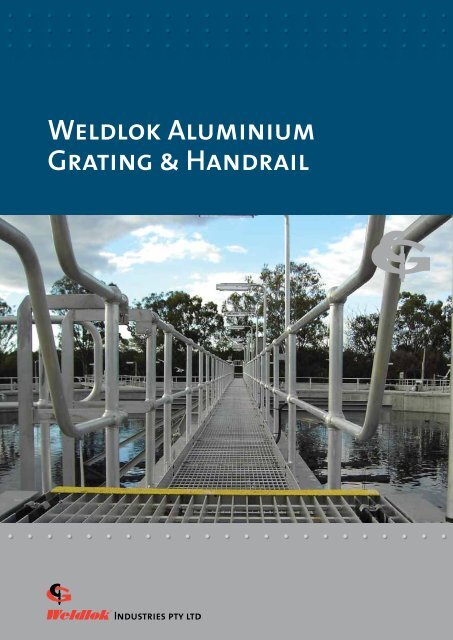
Weldlok Aluminium Grating & Handrail - Graham Group
Weldlok Aluminium Grating & Handrail - Graham Group
Weldlok Aluminium Grating & Handrail - Graham Group

Create successful ePaper yourself
Turn your PDF publications into a flip-book with our unique Google optimized e-Paper software.
<strong>Weldlok</strong> <strong>Aluminium</strong><br />
<strong>Grating</strong> & <strong>Handrail</strong>
Heading Company Profile<br />
<strong>Weldlok</strong> Industries<br />
A member of the <strong>Graham</strong> <strong>Group</strong><br />
An Australian owned company with<br />
more than 50 years’ experience<br />
The <strong>Graham</strong> <strong>Group</strong> is owned by the<br />
Nepean <strong>Group</strong>, one of Australia’s<br />
leading privately owned, diversified<br />
engineering and industrial<br />
manufacturing conglomerates.<br />
<strong>Weldlok</strong> Industries manufactures an<br />
extensive range of fabricated grating<br />
and handrail products in a variety of<br />
materials, including galvanised steel,<br />
stainless steel and aluminium.<br />
<strong>Weldlok</strong> also manufactures steel and<br />
aluminium stair treads, steel stair<br />
stringers and specialist drainage<br />
grates, as well as supplying a range<br />
of fibreglass walkway grating and<br />
handrails.<br />
This brochure is designed to assist the<br />
architect, draughtsperson, engineer,<br />
fabricator and specifier in the correct<br />
selection of our range of aluminium<br />
grating and handrail products.<br />
2<br />
CONTENTS<br />
<strong>Aluminium</strong> <strong>Grating</strong><br />
<strong>Aluminium</strong> Properties 3<br />
Bar <strong>Grating</strong> 4<br />
Stair Treads 6<br />
I-Bar <strong>Grating</strong> 7<br />
Extruded Plank 8<br />
<strong>Grating</strong> Specifications 11<br />
Grate Fastening 12<br />
Fastening Clips 13<br />
Manufacturing Tolerances 14<br />
Installation Tolerances 15<br />
<strong>Grating</strong> Terminology 16<br />
<strong>Aluminium</strong> <strong>Handrail</strong><br />
Specification & Installation 17<br />
Standard Stanchions 18<br />
Single & Multi-Ball Stanchions 19<br />
Base Plates 20<br />
Kick Plate Mounting Brackets 21<br />
Ancillary Products 22<br />
Product Weights 23<br />
Ordering Information 23
<strong>Weldlok</strong><br />
<strong>Aluminium</strong> Products<br />
<strong>Aluminium</strong> has a unique<br />
combination of properties that<br />
makes it one of the most versatile<br />
engineering and construction<br />
materials. Its many advantages<br />
include:<br />
• Excellent corrosion resistance<br />
• High strength-to-weight ratio<br />
• Can be customised on site<br />
• Non-toxic<br />
• Naturally attractive<br />
• Easily recycled<br />
• Our most abundant metallic<br />
element<br />
Rectangular Bar <strong>Grating</strong><br />
I-Bar <strong>Grating</strong><br />
Plank<br />
It is an ideal material for bar grating<br />
because of its low mass (about a<br />
third the weight of copper or steel),<br />
unmatched strength to weight ratio<br />
and excellent corrosion resistance<br />
under most service conditions.<br />
<strong>Aluminium</strong> construction products<br />
provide years of service without<br />
showing wear or decay. Because<br />
aluminium is non toxic, it can easily be<br />
cleaned and does not absorb bacteriasustaining<br />
particles. This makes it an<br />
excellent choice for food processing<br />
facilities. <strong>Aluminium</strong> is also resilient;<br />
it can deflect under loads and then<br />
spring back.<br />
These attributes make aluminium<br />
grating an ideal solution for many<br />
special applications such as sewage<br />
and wastewater treatment plants,<br />
off-shore drilling rigs, some types<br />
of chemical processing plants and<br />
marine superstructure applications. Its<br />
aesthetic appeal also makes aluminium<br />
a natural choice for architectural<br />
and commercial applications such as<br />
sunscreens, ceiling tiles, vents, fencing,<br />
building facades, fountains, walkways<br />
and entranceways.<br />
<strong>Weldlok</strong>® aluminium grating balustrades and FRP walkway at Red Bluff Shared Pathway,<br />
Lake Macquarie, NSW<br />
3<br />
<strong>Weldlok</strong>® aluminium grating at Abbot<br />
Point Coal Terminal, Qld<br />
<strong>Weldlok</strong>® aluminium handrails and FRP walkway at<br />
Palm Beach Jetty, Rockingam, WA
<strong>Weldlok</strong> <strong>Aluminium</strong><br />
Rectangular Bar <strong>Grating</strong><br />
<strong>Grating</strong> is pressure-locked, with<br />
crossbars permanently attached to<br />
load bars through a swaging process.<br />
<strong>Grating</strong> is available with a range of<br />
load bar sizes and spacing. Crossbar<br />
spacing can also be at 50mm or<br />
100mm centres. Also available with<br />
serrated surface for slip resistance.<br />
Rectangular Bar <strong>Grating</strong> is the most<br />
widely used aluminium pressurelocked<br />
grating. The square crossbars<br />
are inserted through punched holes<br />
in the rectangular load bars, then<br />
permanently locked into place by<br />
swaging.<br />
Recessed crossbars provide clean, crisp<br />
lines, while the advanced swaging<br />
process eliminates the need for<br />
welding to form the panels, allowing<br />
for variety of spacing. Its aesthetic<br />
appeal and ability to meet tight<br />
tolerances make this grating ideal for<br />
architectural applications.<br />
<strong>Grating</strong> Profiles<br />
50<br />
100<br />
50<br />
Finishes<br />
A30<br />
30 Load Bar Pitch<br />
B30<br />
30 Load Bar Pitch<br />
B60<br />
60<br />
Load Bar Pitch<br />
<strong>Aluminium</strong> <strong>Grating</strong> is available in<br />
three finishes:<br />
M = Mill Finish<br />
PV = Passivated<br />
A= Anodised<br />
Series 30 Standard Mat Sizes<br />
Load Bar Thickness Span x Width No. of Load Bars<br />
3mm 6000 x 993mm 34<br />
5mm 6000 x 995mm 34<br />
Series 60 Standard Mat Sizes<br />
Load Bar Thickness Span x Width No. of Load Bars<br />
3mm 6000 x 1023mm 18<br />
5mm 6000 x 1025mm 18<br />
Product Code Example<br />
AS 30 – 32 3 A = Series 30 <strong>Aluminium</strong> Rectangular <strong>Grating</strong>, Serrated, Load Bars<br />
32 x 3 at 30mm centres, crossbars at 100mm spacing.<br />
A S 30 – 32 3 A<br />
Cross Bar Pitch<br />
A – 100mm B – 50mm<br />
Load Bar Pitch<br />
30mm or 60mm Centres<br />
(Optional) Serrated Top Surface Profile<br />
4<br />
Load Bar Depth<br />
From 20mm to 65mm<br />
Plain Serrated<br />
<strong>Aluminium</strong><br />
Nominal Load Bar Thickness<br />
3mm or 6mm
<strong>Aluminium</strong> Rectangular <strong>Grating</strong><br />
Safe Load Tables<br />
Product Code<br />
Series 30 Safe Load and Deflection Table<br />
CLEAR SPAN<br />
600 750 900 1050 1200 1350 1500 1650 1800 1950 2100<br />
A30-253A<br />
B30-253A<br />
25x3 30<br />
100<br />
50<br />
967<br />
8.50<br />
10.26<br />
U<br />
D<br />
19.00<br />
3.50<br />
12.10<br />
5.50<br />
8.40<br />
7.90<br />
6.20<br />
10.80<br />
U – Safe uniform load (kg/m<br />
A30-255A<br />
B30-255A<br />
25 x 5 30<br />
100<br />
50<br />
1099<br />
13.00<br />
14.74<br />
U<br />
D<br />
31.60<br />
3.50<br />
20.20<br />
5.50<br />
14.10<br />
7.90<br />
10.30<br />
10.80<br />
7.90<br />
14.10<br />
A30-323A<br />
B30-323A<br />
32 x 3 30<br />
100<br />
50<br />
1164<br />
10.40<br />
11.84<br />
U<br />
D<br />
31.10<br />
2.70<br />
19.90<br />
4.30<br />
13.80<br />
6.20<br />
10.20<br />
8.40<br />
7.80<br />
11.00<br />
A30-325A<br />
B30-325A<br />
32 x 5 30<br />
100<br />
50<br />
1322<br />
16.20<br />
17.90<br />
U<br />
D<br />
51.80<br />
2.70<br />
33.20<br />
4.30<br />
23.00<br />
6.20<br />
16.90<br />
8.40<br />
13.00<br />
11.00<br />
10.20<br />
13.90<br />
A30-403A<br />
B30-403A<br />
40 x 3 30<br />
100<br />
50<br />
1376<br />
12.60<br />
14.37<br />
U<br />
D<br />
48.60<br />
2.20<br />
31.10<br />
3.40<br />
21.60<br />
4.90<br />
15.90<br />
6.70<br />
12.10<br />
8.80<br />
9.60<br />
11.10 13.70<br />
A30-405A<br />
B30-405A<br />
40 x 5 30<br />
100<br />
50<br />
1563<br />
19.80<br />
21.54<br />
U<br />
D<br />
81.00<br />
2.20<br />
51.80<br />
3.40<br />
36.00<br />
4.90<br />
26.40<br />
6.70<br />
20.20<br />
8.80<br />
16.00<br />
11.10<br />
13.00<br />
13.70<br />
10.70<br />
16.60<br />
A30-455A<br />
B30-455A<br />
45 x 5 30<br />
100<br />
50<br />
1708<br />
22.00<br />
23.74<br />
U<br />
D<br />
102.50<br />
2.00<br />
65.60<br />
3.10<br />
45.60<br />
4.40<br />
33.50<br />
6.00<br />
25.60<br />
7.80<br />
20.20<br />
9.90<br />
16.40<br />
12.20<br />
13.60<br />
14.80<br />
11.40<br />
17.60 7.80<br />
A30-505A<br />
B30-505A<br />
50 x 5 30<br />
100<br />
50<br />
1848<br />
24.30<br />
26.03<br />
U<br />
D<br />
126.50<br />
1.80<br />
81.00<br />
2.70<br />
56.20<br />
4.00<br />
41.30<br />
5.40<br />
31.60<br />
7.00<br />
25.00<br />
8.90<br />
20.20<br />
11.00<br />
16.70<br />
13.30<br />
14.10<br />
15.80<br />
12.00<br />
18.60<br />
A30-555A<br />
B30-555A<br />
55 x 5 30<br />
100<br />
50<br />
1985<br />
27.42<br />
29.15<br />
U<br />
D<br />
153.10<br />
1.60<br />
98.00<br />
2.50<br />
68.10<br />
3.60<br />
50.00<br />
4.90<br />
38.30<br />
6.40<br />
30.20<br />
8.10<br />
24.50<br />
10.00<br />
20.20<br />
12.10<br />
17.00<br />
14.40<br />
14.50<br />
16.90<br />
12.50<br />
19.60<br />
A30-655A<br />
B30-655A<br />
65x5 30<br />
100<br />
50<br />
2250<br />
32.10<br />
33.80<br />
U<br />
D<br />
213.90<br />
1.40<br />
136.90 95.00<br />
2.10 3.00<br />
69.80<br />
4.10<br />
53.50<br />
5.40<br />
42.20<br />
6.80<br />
34.20<br />
8.40<br />
28.30<br />
10.20<br />
23.80<br />
12.20<br />
20.20<br />
14.30<br />
17.50<br />
16.60<br />
2 )<br />
D – Deflection (mm)<br />
<strong>Grating</strong> for spans to the left of the heavy line have a<br />
deflection less than 5mm for uniform loads of 4 kPa<br />
When serrated grating is specified, the depth of grating<br />
required for a specific load will be 5mm greather than<br />
that shown in these tables.<br />
Load Bar Alloy 6063-T6<br />
Cross Bar Alloy 6060-T5<br />
Bold type indicates preferred item (likely to be in stock)<br />
Product Code<br />
Load Bar<br />
Size (mm)<br />
Load Bar<br />
Size (mm)<br />
Load Bar<br />
Spacing (mm)<br />
Load Bar<br />
Spacing (mm)<br />
Cross Bar<br />
Spacing (mm)<br />
Cross Bar<br />
Spacing (mm)<br />
Max Span at 4KPa,<br />
5mm deflection<br />
Max Span at 4KPa,<br />
5mm deflection<br />
Weight kg/m 2<br />
Weight kg/m 2<br />
B60-253A 25x3 60 50 813 6.80<br />
B60-255A 25 x 5 60 50 924 9.15<br />
B60-323A 32 x 3 60 50 979 7.80<br />
B60-325A 32 x 5 60 50 1112 10.70<br />
B60-403A 40 x 3 60 50 1157 8.96<br />
B60-405A 40 x 5 60 50 1315 12.65<br />
B60-455A 45 x 5 60 50 1436 13.80<br />
B60-505A 50 x 5 60 50 1554 14.95<br />
B60-555A 55 x 5 60 50 1669 16.50<br />
B60-655A 65 x 5 60 50 1892 18.00<br />
Bold type indicates preferred item (likely to be in stock)<br />
Series 60 Safe Load and Deflection Table<br />
CLEAR SPAN<br />
600 750 900 1050 1200 1350 1500 1650 1800 1950 2100<br />
U 19.00 12.10 8.40<br />
D 7.00 11.00 15.80<br />
U 31.60 20.20 14.10 10.30<br />
D 7.00 11.00 15.80 21.50<br />
U 31.10 19.90 13.80 10.20<br />
D 5.50 8.60 12.40 16.80<br />
U 51.80 33.20 23.00 16.90 13.00<br />
D 5.50 8.60 12.40 16.80 22.00<br />
U 48.60 31.10 21.60 15.90 12.10<br />
D 4.40 6.90 9.90 13.50 17.60<br />
U 81.00 51.80 36.00 26.40 20.20 16.00<br />
D 4.40 6.90 9.90 13.50 17.60 22.20<br />
U 102.50 65.60 45.60 33.50 25.60 20.20 16.40<br />
D 3.90 6.10 8.80 12.00 15.60 19.80 24.40<br />
U 126.50 81.00 56.20 41.30 31.60 25.00 20.20 16.70<br />
D 3.50 5.50 7.90 10.80 14.10 17.80 22.00 26.60<br />
U 153.10 98.00 68.10 50.00 38.30 30.20 24.50 20.20 17.00<br />
D 3.20 5.00 7.20 9.80 12.80 16.20 20.00 24.20 28.80<br />
U 213.90 136.90 95.00 69.80 53.50 42.20 34.20 28.30 23.80 20.20 17.50<br />
D 2.70 4.20 6.10 8.30 10.80 13.70 16.90 20.40 24.30 28.60 33.10<br />
5<br />
U – Safe uniform load (kg/m 2 )<br />
D – Deflection (mm)<br />
<strong>Grating</strong> for spans to the left of the heavy line have a<br />
deflection less than 5mm for uniform loads of 4 kPa<br />
When serrated grating is specified, the depth of grating<br />
required for a specific load will be 5mm greather than<br />
that shown in these tables.<br />
Load Bar Alloy 6063-T6<br />
Cross Bar Alloy 6060-T5
<strong>Weldlok</strong> <strong>Aluminium</strong><br />
Stair Treads<br />
<strong>Weldlok</strong>® aluminium stair treads<br />
are fabricated from rectangular<br />
swaged bar grating. The bar grating<br />
is available with a plain or serrated<br />
surface.<br />
<strong>Aluminium</strong> stair treads are available<br />
with two types of nosing - floor plate<br />
or non-slip yellow abrasive. The<br />
treads can be welded into place or<br />
supplied with pre-drilled holes for<br />
bolting.<br />
Overall tread length can be made to<br />
any dimension. However, <strong>Weldlok</strong><br />
advises that tread dimensions<br />
be selected from the tables of<br />
recommended widths and maximum<br />
lengths below.<br />
Stair Tread Types<br />
T3 Floor plate nosing (weld-in)<br />
T4 Floor plate nosing (bolt-in)<br />
T5 Yellow abrasive nosing (weld-in)<br />
T6 Yellow abrasive nosing (bolt-in)<br />
Recommended Widths<br />
Series 30 125 155 185 215 245 275 305<br />
Series 60 185 245 275 305<br />
Bolted Connections<br />
End Plate Hole Centres “A” 45 75 75 100 100 100 100<br />
Recommended Max. Lengths<br />
Load Bar Size 25 x 5 32 x 5 40 x 5<br />
Series 30 550 900 1275<br />
Series 60 450 700<br />
Standard End Plates for Bolted T E D TThreads R E A D S<br />
50<br />
65<br />
FRONT<br />
25<br />
Ø14mm<br />
RECOMMENDED WIDTH<br />
‘A’<br />
Note: Special End Plate Hole Centres available on request.<br />
6<br />
25<br />
T3 floor plate nosing (weld-in)<br />
T4 floor plate nosing (bolt-in)<br />
T5 yellow abrasive nosing (weld-in)<br />
T6 yellow abrasive nosing (bolt-in)<br />
35º SNIPE TO ALL TREADS<br />
(UNLESS REQUESTED OTHERWISE)
<strong>Weldlok</strong> <strong>Aluminium</strong><br />
I-Bar <strong>Grating</strong><br />
I-Bar is an attractive and reasonably<br />
priced alternative to rectangular bar<br />
grating. Extruded I- Bar sections have<br />
a similar load carrying capacity, with<br />
less weight per square metre, than<br />
rectangular bars.<br />
Striated load bar provides built-in slip<br />
resistance without the added cost of<br />
serration.<br />
<strong>Aluminium</strong> I-Bar <strong>Grating</strong> Series 30<br />
Load Bar<br />
Spacing mm<br />
Load Bar Size<br />
Max. Span at 4 kPa<br />
5mm deflection<br />
Weight kg/m 2<br />
30 25 x 6 1120 9.72<br />
30 32 x 6 1320 11.42<br />
30 40 x 6 1495 13.18<br />
30 45 x 6 1670 14.94<br />
30 50 x 6 1855 16.75<br />
30 55 x 6 2030 18.31<br />
30 65 x 6 2210 20.26<br />
7<br />
6.35mm<br />
I Bar<br />
End View<br />
I-Bar <strong>Grating</strong> Profiles<br />
CLEAR SPAN<br />
600 750 900 1050 1200 1350 1500 1650 1800 1950 2100 2400<br />
U 3085 2465 2055 1762 1543<br />
D 2.92 4.57 6.57 8.96 11.7<br />
U 4819 3852 3212 2753 2407 2143<br />
D 2.33 3.65 5.25 7.16 9.35 11.86<br />
U 6938 5551 4623 3964 3471 3085 2773<br />
D 1.95 3.048 4.39 5.69 7.79 9.88 12.19<br />
U – Safe uniform load (kg/m2 )<br />
D – Deflection (mm)<br />
<strong>Grating</strong> for spans to the left of the heavy line have a<br />
deflection less than 5mm for uniform loads of 4 kPa<br />
U 9442 7553 6292 5395 4721 4199 3779 3432 3149<br />
D 1.67 2.61 3.76 5.13 6.68 8.45 10.46 12.65 15.06<br />
U 12333 9867 8222 7050 6166 5483 4936 4487 4111 3793<br />
D 1.47 2.286 3.30 4.47 5.84 7.41 9.14 11.07 13.15 15.44<br />
U 15609 12489 10409 8920 7807 6938 6244 5678 5204 4804 4462<br />
D 1.29 2.03 2.92 3.98 5.2 6.57 8.12 9.83 11.71 13.74 15.95<br />
U 19270 15418 12850 11014 9638 8563 7709 7006 6425 5932 5507 4819<br />
D 1.168 1.83 2.64 3.58 4.67 5.92 7.31 8.84 10.54 12.37 14.35 18.72<br />
50<br />
100<br />
A 30<br />
30 Load Bar Pitch<br />
B 30<br />
30 Load Bar Pitch<br />
Other load bar spacings such as 24, 17,<br />
11 Series are available on request
<strong>Weldlok</strong> <strong>Aluminium</strong> Plank<br />
Extruded aluminium grating available<br />
in 150mm wide sections, either plainsided<br />
or interlocking. Plank can be<br />
provided in sections up to 8 metres in<br />
length.<br />
<strong>Aluminium</strong> Plank is a structurally<br />
sound and attractive alternative to<br />
bar grating. The planks are relatively<br />
maintenance-free and have no<br />
separate parts to work loose or<br />
splinter.<br />
Available unpunched as an<br />
economical and structurally<br />
superior substitute for aluminium<br />
checkerplate, or with a variety of<br />
punched patterns for the passage of<br />
air, light, heat or moisture. A diagonal<br />
punched pattern is also available for<br />
wheelchair accessibility and high-heel<br />
foot traffic.<br />
Interconnecting webs provide a<br />
flush walking surface for maximum<br />
foot contact and comfort. Planks<br />
are also an economical alternative in<br />
applications requiring open grating<br />
with plate attached to the top<br />
surface.<br />
Typical applications include<br />
wastewater treatment plants to<br />
reduce odours, as entranceways,<br />
walkways on bridges and walking<br />
trails, in marine refrigeration,<br />
stadiums, etc.<br />
Heavy Duty (Plain Sides)<br />
30mm 30mm<br />
Heavy Duty (Interlocking Sides)<br />
30mm<br />
150mm<br />
30mm 30mm<br />
Female Edge Male Edge<br />
Light Series (Plain Sides)<br />
60mm<br />
150mm<br />
30mm<br />
150mm<br />
8<br />
19mm to<br />
63.5mm<br />
25mm<br />
only<br />
25mm<br />
only
<strong>Weldlok</strong> <strong>Aluminium</strong> Plank<br />
Punch Patterns<br />
<strong>Aluminium</strong> Plank is available<br />
unpunched or with a variety of<br />
punched patterns as shown.<br />
Rectangular or square punched holes<br />
are most commonly used for water<br />
and waste treatment plants and<br />
in marine applications. The Plank<br />
surface can be supplied plain or with<br />
one of two styles of upsets (OGI or<br />
Unpunched Upset Pattern Plain Pattern<br />
WACO) designed to promote a slipresistant<br />
walkway, especially in the<br />
presence of moisture, oil or other<br />
spilled substances.<br />
Diagonal punched patterns meet<br />
specifications for high-heel and<br />
wheelchair traffic.<br />
Unpunched Square Punched Rectangular Punched<br />
Upset Pattern (OGI)<br />
38mm<br />
9<br />
Upset Pattern (OGI) Upset Pattern (WACO)<br />
AL Plank 8* AL Plank 15* AL Plank 22*<br />
19mm<br />
Diagonal Punched<br />
13mm<br />
Plain Pattern<br />
*number indicates % open area
<strong>Weldlok</strong> <strong>Aluminium</strong> Plank<br />
Safe Load & Deflection Tables<br />
Plank Depth<br />
(mm)<br />
19 990 10.74 8.78 9.76<br />
25 1244 12.69 10.74 11.72<br />
32 1473 15.62 13.67 14.65<br />
38 1702 18.55 16.60 17.57<br />
45 1905 21.48 19.53 20.50<br />
50 2108 23.92 21.97 22.95<br />
57 2311 26.85 24.41 25.87<br />
63.5 2463 28.80 26.85 27.83<br />
Plank Depth<br />
(mm)<br />
Max. Span at 4 kPa<br />
5mm deflection<br />
Max. Span at 4 kPa<br />
5mm deflection<br />
Non<br />
Punched<br />
Non<br />
Punched<br />
Weight kg/m 2<br />
Rect.<br />
Punched<br />
Weight kg/m 2<br />
Rect.<br />
Punched<br />
Square<br />
Punched<br />
Square<br />
Punched<br />
25 25 10.25 8.30 9.27<br />
Heavy Duty<br />
Clear Span (mm)<br />
600 750 900 1050 1200 1350 1500 1650 1800 1950 2100 2400<br />
U 2123 1357 942 693 527 415 337<br />
D 3.07 6.02 8.68 11.81 15.44 19.55 24.13<br />
U 4067 2602 1806 1328 1015 800 649 537 449<br />
D 3.15 4.9 7.08 9.65 12.6 15.95 19.68 23.82 28.37<br />
U 7148 4570 3173 2333 1787 1411 1142 942 791 674 581 444<br />
D 2.71 4.24 6.12 8.33 10.87 13.76 16.99 20.57 24.48 28.72 33.32 43.53<br />
U 10580 6772 4702 3451 2641 2089 1689 1396 1171 1001 859 659<br />
D 2.28 3.58 5.15 7.03 9.19 11.63 14.37 17.37 20.7 24.28 28.16 36.8<br />
U 14608 9349 6493 4770 3652 2885 2333 1928 1621 1381 1191 913<br />
D 1.98 3.12 4.49 6.12 8.00 10.11 12.49 15.11 17.98 21.13 24.48 32.00<br />
U 19407 12420 8622 6337 4848 3832 3105 2563 2153 1835 1582 1210<br />
D 1.75 2.74 3.96 5.38 7.03 8.91 10.99 13.31 15.85 18.59 21.56 28.17<br />
U 24944 15965 11083 8143 6234 4926 3989 3295 2768 2358 2036 1557<br />
D 1.55 2.41 3.48 4.75 6.2 7.85 9.7 11.73 13.97 16.41 19.02 24.86<br />
U 29153 18655 12958 9515 7284 5756 4662 3852 3237 2758 2377 1821<br />
D 1.39 2.18 3.15 4.30 5.61 7.08 8.76 10.62 12.62 14.83 17.19 2245<br />
Light Series<br />
Clear Span (mm)<br />
600 750 900 1050 1200 1350 1500 1650 1800 1950 2100 2400<br />
U 2665 1704 1181 869 664 522<br />
D 2.87 4.49 6.45 8.81 11.48 14.48<br />
10<br />
U – Safe uniform load (kg/m2 )<br />
D – Deflection (mm)<br />
<strong>Grating</strong> for spans to the left of the heavy line have a<br />
deflection less than 5mm for uniform loads of 4 kPa
<strong>Weldlok</strong> <strong>Aluminium</strong> <strong>Grating</strong><br />
Specifications<br />
These specifications are<br />
intended as a guide for<br />
architects and engineers,<br />
and should be modified to<br />
fit the specific conditions<br />
of the application.<br />
General<br />
The contractor shall provide all labour,<br />
materials, equipment and incidentals<br />
as specified to install grating and stair<br />
treads.<br />
Site measurements should be taken<br />
prior to preparation of shop drawings<br />
and fabrication, where required, to<br />
ensure proper fitting of the work.<br />
Submittals<br />
The contractor shall submit for<br />
approval shop drawings for the<br />
fabrication and erection of all work,<br />
including plans, elevations and details<br />
of sections and connections. Type and<br />
location of all fasteners should be<br />
shown.<br />
The contractor shall submit the<br />
manufacturer’s specifications, load<br />
tables, anchor details and standard<br />
installation details.<br />
Products<br />
Specify complete product details. For<br />
example:<br />
<strong>Grating</strong>: <strong>Aluminium</strong> Rectangular Bar<br />
by <strong>Weldlok</strong> Industries, or approved<br />
equivalent.<br />
Load Bars: Rectangular bars at<br />
maximum 60mm centres.<br />
Crossbars: Locked at right angles<br />
to load bars at maximum 100mm<br />
centres (50mm cross-bar centres may<br />
be specified at the discretion of the<br />
architect/engineer).<br />
Loading: <strong>Grating</strong> to carry a<br />
pedestrian loading equal to a<br />
uniform load of 2.5kN per square<br />
metre over the required clear span,<br />
with deflection not to exceed 5mm.<br />
(Alternate loading requirement may<br />
be specified at the discretion of the<br />
architect/engineer in accordance with<br />
AS1657.)<br />
Surface: Plain. (Serrated surface<br />
may be specified for maximum slip<br />
resistance.)<br />
Finish: Mill finish, passivated,<br />
anodised.<br />
Stair Treads: Specify same type and<br />
spacing as grating.<br />
Tread Nosing: Specify whether<br />
nosing is floor plate or abrasive yellow<br />
nosing. (Carrier End Plate angles<br />
should be specified in conjunction<br />
with close mesh grating treads.)<br />
Installation<br />
Prior to grating installation, the<br />
contractor shall inspect supports for<br />
correct size, layout and alignment.<br />
Any inconsistencies between contract<br />
drawings and supporting structure<br />
deemed detrimental to grating<br />
placement shall be reported in writing<br />
to the architect or owner’s agent prior<br />
to grating placement.<br />
<strong>Grating</strong> shall be installed in<br />
accordance with shop drawings and<br />
standard installation clearances.<br />
Fitting & Placement<br />
Before installation, all cutting and<br />
fitting required for installation should<br />
be completed. <strong>Grating</strong> shall be placed<br />
so that cross-bars align.<br />
11<br />
Wherever grating is pierced by pipes,<br />
ducts and structural members,<br />
openings must be cut neatly and<br />
accurately to size and a rectangular<br />
band bar of the same height and<br />
material as the load bars welded to<br />
the opening, unless a kick plate is<br />
required by AS1657.<br />
Cut-outs for circular obstructions are<br />
to be at least 50mm larger in diameter<br />
than the obstruction. Cut-outs for all<br />
piping 100mm or less shall be made<br />
on site.<br />
All rectangular cut-outs are to be<br />
made to the next load bar beyond the<br />
penetration, with a clearance not to<br />
exceed load bar spacing.<br />
Standard panel widths shall be used<br />
wherever possible.<br />
Protection of <strong>Aluminium</strong><br />
Where aluminium surfaces come<br />
into contact with dissimilar materials<br />
such as dissimilar metals, concrete,<br />
masonry or lime mortar, exposed<br />
aluminium surfaces shall be painted<br />
with one coat of bituminous paint or<br />
other approved insulating material.<br />
Where stainless steel fasteners are<br />
used these should be isolated from<br />
the aluminium by <strong>Weldlok</strong> nylon<br />
separation washers.<br />
<strong>Grating</strong> Attachment<br />
Appropriate fixing devices (such as<br />
clips, clamps and anchor blocks) and<br />
fasteners must be used to secure<br />
grating to supporting members or<br />
prepared openings. <strong>Grating</strong> fixing<br />
should be installed with a minimum<br />
of four per panel or four per square<br />
metre, whichever is greater.
<strong>Weldlok</strong> <strong>Aluminium</strong> <strong>Grating</strong><br />
Fastening Methods<br />
<strong>Weldlok</strong> fixing clips are recommended<br />
to secure grating to supporting<br />
members. A minimum of 4 clips<br />
should be used per panel or 4 per<br />
square metre, whichever is greater.<br />
30 Series<br />
<strong>Aluminium</strong> Saddle Clip<br />
Suitable for 30 Series grating.<br />
Comprises extruded aluminium top<br />
clip, 8mm diameter hex head screw<br />
and threaded bent bottom clip.<br />
Material: 6063 <strong>Aluminium</strong> Alloy<br />
(Top Clip)<br />
Stainless Steel 316<br />
(Bottom Clip/Screw)<br />
30 Series<br />
SS316 Clip Set<br />
Suitable for Series 30 <strong>Grating</strong>.<br />
Comprises top clip, 8mm diameter<br />
hex head screw, nyloc nut and folded<br />
bottom clamping bracket.<br />
Material: Stainless Steel 316<br />
60 Series<br />
SS316 Clip Set<br />
Suitable for Series 30 & 60 <strong>Grating</strong>.<br />
Comprises double saddle clip, 8mm<br />
diameter hex head screw, nyloc nut<br />
and folded bottom clamping bracket.<br />
Material: Stainless Steel 316<br />
12
<strong>Weldlok</strong> <strong>Aluminium</strong> <strong>Grating</strong><br />
Fixing Clips<br />
Top Clips<br />
30mm<br />
Ø9 HOLE<br />
25 to 65mm<br />
30 Series <strong>Aluminium</strong> Saddle Top Clip<br />
Bottom Clips<br />
Ø8.4 x 40 SLOT<br />
Folded SS316 Bottom Clip<br />
Ø8.6 HOLE<br />
R4.5<br />
30mm<br />
13<br />
20 to 65mm<br />
30 Series SS316 Clip Top<br />
94°<br />
Ø8.5°<br />
M8 TAPED<br />
Threaded SS316 Bent Bottom Clip<br />
30mm<br />
60mm<br />
NYLON INSERT<br />
Ø8.3mm<br />
20 to 65mm<br />
60 Series SS316 Clip Top<br />
60 or 100mm<br />
M8 SCREW<br />
SS316 M8 Screw with Nyloc Nut<br />
(length 65mm & 100mm)
<strong>Weldlok</strong> <strong>Aluminium</strong> <strong>Grating</strong><br />
Manufacturing Tolerances<br />
Overall Dimensions and Squareness<br />
All dimensions are maximum permissible tolerances<br />
Stair Tread Tolerances<br />
Width ± 3mm<br />
Load Bar Length ± 3mm<br />
3mm<br />
D<br />
5mm thick edge bars<br />
supplied as standard<br />
Length +0mm/-3mm<br />
Note: Length of tread is distance between outer faces of end flats<br />
Stair Tread End Flat Lean<br />
Width (W) ± 2mm<br />
c-c ± 0.8mm<br />
W1 = W ± 2mm<br />
Standard Fabrication Welding<br />
Edge bars and attachments are welded with a<br />
minimum 3mm fillet weld to one side of:<br />
Every 4th load bar on Series 30 <strong>Grating</strong><br />
Every 3rd load bar on Series 60 <strong>Grating</strong><br />
Fabrication: Edge bars and end plates welded on<br />
side of every load bar with minimum 3mm fillet weld<br />
3mm<br />
(Cross Bar Projection)<br />
D1 = D ± 3.5mm<br />
D and D1 are overall diagonal<br />
dimensions<br />
W and W1 are overall<br />
dimensions across the load<br />
bars at opposite end of panel<br />
Optional Welding<br />
Full Weld:<br />
Weld one side of every load bar.<br />
Seal Weld:<br />
Weld both sides of every load bar.<br />
1mm<br />
25mm<br />
14<br />
Longitudinal Bow<br />
1/1000 of length Load Bars<br />
Transverse Bow<br />
(Before fastening to supports)<br />
1mm per 200mm of width<br />
1mm per 200mm of width<br />
Load Bars
<strong>Weldlok</strong> <strong>Aluminium</strong> <strong>Grating</strong><br />
Installation Tolerances<br />
Overall Installation Dimensions<br />
All dimensions are maximum permissible tolerances<br />
Panel Length Panel Length<br />
10mm Nominal<br />
Cut-outs around pipes and circular ducts must have<br />
minimum clearance of 25mm all round<br />
15<br />
10mm<br />
Nominal<br />
Actual cut-out taken to nearest load bar<br />
Panel<br />
Width<br />
Panel<br />
Width<br />
Min. 25mm<br />
Bearing (Typical)<br />
Load Bar (Typical)<br />
10mm Nominal<br />
10mm 10mm 10mm 10mm<br />
Min. clearance<br />
equal to<br />
rebate angle<br />
thickness<br />
Note: Clearance can vary relative<br />
to straightness of rebate angle<br />
15mm<br />
Load Bar (Typical)<br />
10mm Nominal
<strong>Weldlok</strong> <strong>Aluminium</strong> <strong>Grating</strong><br />
<strong>Grating</strong> Terminology<br />
Load Bearing Bar<br />
A load-carrying member spanning<br />
between supports.<br />
Span<br />
Cross Bar<br />
A member fixed at right angles to the<br />
load bearing bars to provide lateral<br />
restraint.<br />
Edge Bar<br />
Non-load-bearing bars, running at<br />
right angles to the load-bearing<br />
members.<br />
Nett Area<br />
Support Centres<br />
Length (Direction of Span)<br />
The overall dimension of a panel<br />
parallel to the load-bearing bars.<br />
Length (Span)<br />
Width<br />
The overall dimension of a<br />
panel at right angles to the<br />
load- bearing bars.<br />
Serrations<br />
The area of flooring remaining after deducting cut-outs<br />
([A x B] – [C x D]).<br />
Notches formed in the top of<br />
load-bearing bars to improve slip<br />
resistance.<br />
16<br />
Width<br />
Gross Area<br />
Nosing Bar<br />
A member attached to the front<br />
edge of a stair tread or top stair<br />
landing panel.<br />
Kick Plate<br />
A large, flat bar welded to the side of<br />
a panel or ends and around cut-outs,<br />
where specified. Nominally 100mm<br />
above walking surface.<br />
Cut-Outs<br />
Area of flooring removed to clear<br />
around columns, pipes, machinery, etc.<br />
Total area of flooring, including cut-outs (A x B).
<strong>Aluminium</strong> <strong>Handrail</strong><br />
Specification & installation<br />
Stanchions<br />
Stanchions are manufactured from<br />
aluminium tubing 50mm OD x 4.0mm<br />
wall thickness. Ball size is 76mm OD x<br />
2.0mm wall thickness.<br />
Stanchion Pitching<br />
Australian Standard AS1657:1992<br />
recommends a maximum spacing for<br />
stanchions of 1800mm centres. All<br />
warranties become void if the system<br />
is not erected in compliance with this<br />
standard.<br />
Stanchion Handing<br />
Handing of stanchions is from point<br />
of view on stairway or platform,<br />
facing the inside of the stanchion.<br />
Those on the right-hand side are<br />
suffixed ‘R’, those on the left-hand<br />
side are suffixed ‘L’.<br />
Rails<br />
Standard drilled openings on<br />
stanchions allow for a top rail<br />
(handrail) of 46mm OD and a mid-rail<br />
(knee-rail) of 38.1mm OD. Rails are<br />
supplied in standard lengths of 6.0m.<br />
<strong>Handrail</strong> (HR): 46mm OD x 39mm ID.<br />
Mass = 1.34 kg/m (6.0m = 8.04kg).<br />
Knee-rail (KR): 38.1mm OD x 34.1 ID.<br />
Mass = 0.97 kg/m (6.0m = 5.82kg)<br />
Kick Plate Mounting Brackets<br />
Kick plate mounting brackets (KPMB)<br />
are manufactured from 40mm x<br />
40mm x 6mm angle x 93mm long,<br />
with a mass of 0.11kg each. Holes are<br />
14mm diameter at 51mm centres to<br />
suit 100mm high kick plate.<br />
Kick Plates<br />
Standard kick plates (KP) are 100mm<br />
x 6mm flat in 4.0m lengths, with a<br />
mass of 1.62 kg/m (4.0m = 6.48kg).<br />
Splice plates (KPSP) are 100mm x<br />
80mm x 6mm with a mass of 0.13kg<br />
each. All kick plates have two slotted<br />
holes at each end, 14mm diameter x<br />
27mm long.<br />
Base Plates<br />
Base plates are manufactured in<br />
standard, angle-mounted and corner<br />
versions. For details see page 20.<br />
Materials<br />
<strong>Weldlok</strong> can supply detailed material<br />
specifications on request. Generally,<br />
aluminium Grade 6000 series is used<br />
throughout.<br />
Finish<br />
Standard finish is passivated natural<br />
aluminium. Optional finishes include<br />
anodising and powder coating, which<br />
can be done off-site.<br />
Separation Washers<br />
<strong>Weldlok</strong> recommends the use of<br />
nylon separation washers between<br />
dissimilar metals. These can be<br />
supplied with the handrail.<br />
17<br />
General Installation<br />
Instructions<br />
1. Loosely bolt stanchions to<br />
structure.<br />
2. Feed top rails and mid-rail through<br />
ball joints.<br />
3. Where top or mid-rails join, use slip<br />
joint.<br />
4. Drill for taper pins. (Ensure the<br />
join is inside the ball unit, where<br />
possible.)<br />
5. Tighten nuts and bolts on<br />
stanchions.<br />
6. Run approximately 25mm (1 inch) of<br />
weld on side or top where ball units<br />
join top and mid-rails (not required<br />
when using tapered pins).<br />
7. Bends and corners to be fully<br />
welded then ground and primed<br />
with zinc-rich paint.
<strong>Weldlok</strong> <strong>Aluminium</strong> <strong>Handrail</strong><br />
Standard Stanchions<br />
Standard Stanchions<br />
457<br />
457<br />
505<br />
505<br />
457<br />
457<br />
560<br />
560<br />
484<br />
θ°<br />
457<br />
560 150<br />
150<br />
75<br />
18<br />
6<br />
θ°<br />
θ°<br />
θ°<br />
560 560 457 457<br />
484 θ° θ°<br />
θ°<br />
75 DIA.<br />
θ°<br />
AW AWA AWAA<br />
AC ACA ABP ABPA ABPAM<br />
457<br />
457<br />
636 636<br />
76<br />
ASMC ASM ASMAL ASMAR<br />
“O ”<br />
R100<br />
“O ”<br />
“O ”<br />
(End views)<br />
ASMC ASM ASMAL<br />
END VIEWS<br />
END VIEWS<br />
35<br />
76<br />
55<br />
35<br />
35<br />
ASMC CONVEYOR ASM TYPE<br />
76<br />
55<br />
35<br />
ASMAR<br />
64 on<br />
125 x 65<br />
CHANNEL<br />
64 on<br />
125 x 65<br />
CHANNEL<br />
64 on<br />
125 x 65 76 OFFSET<br />
CHANNEL (See table)<br />
ASMO “O ”<br />
64 on<br />
Offset 125 x 65 “O” (mm) OFFSET<br />
CHANNEL (See table)<br />
Channel “O” offset<br />
ASMO<br />
125 x 65 115<br />
150 x 75 115<br />
180 x 75 115<br />
200 x 75 115<br />
230 x 75 115<br />
250 x 90 120<br />
300 x 90 120<br />
380 x 100 135<br />
“O ”<br />
“O ”<br />
ASMOAL (End views) ASMOAR<br />
Universal Beam “O” offset<br />
ASMOAL ASMOAR<br />
200 115<br />
250 135<br />
310 135<br />
360 135<br />
410 135<br />
460 150<br />
Side Mounted<br />
ASMC CONVEYOR ASM TYPE<br />
Side Mounted Offset<br />
457<br />
505<br />
636<br />
484<br />
θ°<br />
AW AWA AWAA<br />
AC ACA ABP ABPA ABPAM<br />
457<br />
505<br />
636<br />
θ°<br />
560 560 457 457<br />
θ°<br />
θ°<br />
Welded Collar Base Plate<br />
θ°<br />
Hand when<br />
facing up<br />
the stairs<br />
θ°<br />
θ°<br />
Hand when<br />
facing up<br />
the stairs<br />
θ°<br />
457<br />
560<br />
6<br />
θ°<br />
DIA.<br />
560<br />
560<br />
560 560 457 457<br />
484 θ° θ°<br />
V iew up<br />
the stairs<br />
V iew up<br />
the stairs<br />
R100<br />
θ°
<strong>Weldlok</strong> <strong>Aluminium</strong> <strong>Handrail</strong><br />
Single & Multi-Ball Stanchions<br />
Standard Single Ball Stanchions<br />
Multi Ball Stanchions<br />
178<br />
ASBBP ASBBP<br />
D.O.S.O. ASBSM<br />
D.R.S.O.<br />
Single Ball Base Plate Single Ball Side Mounted<br />
100<br />
100<br />
ASBH ASBH<br />
End view D.R.S.O.<br />
ASBH<br />
D.L.S.O.<br />
(Hand as if bolted to wall)<br />
Single Ball Offset <strong>Handrail</strong> Single Ball Welded<br />
*<br />
*<br />
*<br />
*<br />
*<br />
220<br />
50 x 10<br />
M.S. FLAT<br />
60<br />
20<br />
18mm DIA.<br />
HOLES<br />
100<br />
PR PRR<br />
This system is mounted on<br />
road impact barriers<br />
19<br />
*<br />
254<br />
ASBSM ASBSM<br />
D.L.S.O.<br />
*<br />
θ° θ°<br />
ASBW ASBWA ASBWAA<br />
102<br />
146<br />
* Nominate dimensions<br />
Available in all base plate types<br />
75 x 10<br />
M.S. FLAT<br />
TYPICAL BASE PLATE<br />
(Except type BPAM)<br />
18mm DIA.<br />
HOLES<br />
θ°<br />
θ°<br />
44<br />
82<br />
172<br />
18mm DIA.<br />
HOLES<br />
100<br />
50<br />
65<br />
100<br />
50<br />
CORNER POST<br />
(Type BP only)<br />
ABP ABPAM BASE OF BPAM ASM C-TYPE ASMO<br />
*Specify number of balls, pitching & height required of stanchion (150mm minimum centres)<br />
Multi ball stanchions are available in any of the range of configurations<br />
75<br />
150<br />
65<br />
6<br />
θ°<br />
100 x 10<br />
M.S. FLAT
WM<br />
SM<br />
TO SUIT REQUIREMENTS<br />
<strong>Weldlok</strong> <strong>Aluminium</strong> <strong>Handrail</strong><br />
457<br />
457<br />
Special Drilling & Base Plates<br />
560<br />
457<br />
Special Drilling for Rails<br />
TO SUIT REQUIREMENTS<br />
170<br />
126<br />
80x12<br />
OFFSET “O”<br />
(See table over)<br />
ANGLE MOUNTED ONLY<br />
70<br />
152<br />
560<br />
SM<br />
PMCNR<br />
76<br />
SOM MB<br />
505<br />
76<br />
636<br />
88<br />
Typical hole size ref note 5<br />
D.O.S.O. STANCHIONS WITH CHAIN HOOKS<br />
Specify whether top rail only or both rails<br />
5mm heavy 88 duty 150 chain available on request<br />
150<br />
CORNER BASE PLATE ONLY<br />
457<br />
0.6kg<br />
SM<br />
DRILLED<br />
LEFT HAND<br />
SIDE ONLY<br />
DRILLED 146<br />
TOP<br />
102<br />
SIDE ONLY<br />
DRILLED<br />
BOTTOM<br />
SIDE ONLY<br />
170<br />
126<br />
CORNER<br />
POST<br />
80x12<br />
DRILLED ONE SIDE ONLY 80 (D.O.S.O.)<br />
These combinations of drilling are available on full range of standard stanchions<br />
ANGLE MOUNTED ONLY<br />
560<br />
STANDARD BASE PLATE<br />
TO SUIT REQUIREMENTS<br />
70<br />
TO SUIT REQUIREMENTS<br />
PMCNR<br />
CM SCM SOM MB<br />
DRILLED<br />
RIGHT HAND<br />
SIDE ONLY<br />
Standard Base Plates<br />
560<br />
76<br />
88<br />
636<br />
146<br />
170<br />
102<br />
5mm CHAIN<br />
126<br />
55<br />
80<br />
80<br />
OFFSET “O”<br />
(See table over)<br />
80x12<br />
STANDARD BASE PLATE<br />
ANGLE MOUNTED ONLY<br />
5mm CHAIN<br />
88 150<br />
150<br />
CORNER BASE PLATE ONLY<br />
0.6kg<br />
20<br />
TO SUIT REQUIREMENTS<br />
146<br />
102<br />
STANDARD BASE PLATE<br />
70<br />
88<br />
80<br />
88 150<br />
35<br />
150<br />
CORNER BASE PLATE ONLY<br />
50<br />
90°<br />
0.6kg<br />
8mm DIA.<br />
Typical DETAIL hole OF HOOK size ref note 5
“C”<br />
“C”<br />
<strong>Weldlok</strong> <strong>Aluminium</strong> <strong>Handrail</strong><br />
Closures & Kick Plates<br />
457<br />
Standard Closures, Joiners and Bends<br />
457<br />
ACB<br />
51<br />
300<br />
R130<br />
ACB<br />
93<br />
267<br />
300<br />
R130<br />
267<br />
CLOSURES<br />
CLOSURES<br />
θ°<br />
<strong>Grating</strong> or<br />
plate thickness<br />
<strong>Grating</strong> or<br />
plate thickness<br />
267<br />
300<br />
300<br />
ACBA<br />
TOP<br />
ACBA<br />
TOP<br />
14mm Dia.<br />
slotted holes<br />
14mm Dia.<br />
slotted holes<br />
“C” “C” “C”<br />
θ°<br />
Note: AWKick plate mounting AC brackets are ABPan optional extra ASM ASMO<br />
267<br />
Kick Plate Mounting Brackets<br />
51<br />
93<br />
“C” “C” “C”<br />
AW AC ABP ASM ASMO<br />
40<br />
40<br />
457<br />
457<br />
“C”<br />
“C”<br />
21<br />
300<br />
267<br />
300<br />
R130<br />
θ° R130<br />
Nominal rail size<br />
R130<br />
θ° & bend R130angle<br />
ASB Nominal ASBA rail size<br />
& bend angle<br />
BENDS<br />
ASB Special lengths available ASBA<br />
BENDS<br />
Special lengths available<br />
Drill 5mm holes for taper pins<br />
(Pins are zinc plated)<br />
Drill 5mm holes for taper pins<br />
(Pins are zinc plated)<br />
267<br />
300 150<br />
Gap shown<br />
for clarity<br />
300<br />
ACBA<br />
BOTTOM<br />
ACBA<br />
BOTTOM<br />
150<br />
RAIL JOINER<br />
(SLIP JOINT)<br />
RAIL Nominate JOINER rail size<br />
(SLIP JOINT)<br />
Nominate rail size<br />
Gap shown<br />
for clarity<br />
“C”<br />
“C”<br />
300<br />
40 x 40 x 5 x 85 LG<br />
angle<br />
40 x 40 x 5 x 85 LG<br />
angle<br />
“C”<br />
300<br />
“C”<br />
48<br />
48<br />
300<br />
300<br />
40<br />
40<br />
300<br />
300<br />
Dimension “C” (mm)<br />
Type<br />
“C” = <strong>Grating</strong> or<br />
Plate Thickness Plus<br />
W 33<br />
C 33<br />
BP 33<br />
SM 109*<br />
SMO 109*<br />
*94 when used on 125 x 65<br />
Example:<br />
If grating is 25mm deep then<br />
“C” Dimension = 55mm<br />
for types W, C, & BP.
<strong>Weldlok</strong> <strong>Aluminium</strong> <strong>Handrail</strong><br />
Ancillary Products<br />
Balustrades<br />
1017 STANDARD<br />
894 STANDARD<br />
(123)<br />
Light Poles<br />
Note: Light pole welded to<br />
Standchion at time of manufacture.<br />
Stanchion type to be specified at<br />
time of ordering.<br />
Light Pole material is<br />
46 OD x 3.5mm wall thickness.<br />
Stanchion diameter 50mm,<br />
<strong>Handrail</strong> diameter 46mm.<br />
Self-Closing Gates<br />
All gates are manufactured with<br />
316 SS spring closures and nylon<br />
bearings to guarantee years of<br />
fault-free service.<br />
Kick plates are only required on<br />
platforms that are 2m or higher.<br />
MANUFACTURED TO ORDER<br />
1500mm Maximum<br />
MANUFACTURED TO ORDER<br />
1500mm Maximum<br />
MANUFACTURED TO ORDER<br />
1500mm Maximum<br />
1800 CENTRES MAXIMUM<br />
Mass = 3.85kg + mass of stanchion<br />
100<br />
300<br />
100<br />
R150<br />
457<br />
Mass = 3.85kg + mass of stanchion<br />
LIGHT FITTING<br />
60100<br />
Mass = 3.85kg SUPPLIED + mass BY OTHERS of stanchion<br />
100<br />
300<br />
300<br />
100<br />
2167<br />
100 R150<br />
457<br />
R150<br />
457<br />
* 636<br />
RADIUS<br />
130<br />
1017<br />
LIGHT FITTING<br />
SUPPLIED BY OTHERS<br />
LIGHT FITTING<br />
60<br />
SUPPLIED BY OTHERS<br />
60<br />
2167<br />
* 76<br />
40<br />
2167<br />
80<br />
Max<br />
Tested Offset 150mm*<br />
636<br />
* RADIUS<br />
636<br />
130<br />
RADIUS Notes:<br />
130<br />
* 76<br />
80<br />
* 76<br />
80<br />
Max<br />
Tested Offset 150mm<br />
Max<br />
Tested Offset 150mm<br />
MANUFACTURED TO ORDER<br />
3000mm Maximum<br />
22<br />
1017 STANDARD<br />
894 STANDARD<br />
(123)<br />
1017<br />
1017<br />
1. All gate stanchions can be ordered<br />
to suit individual requirements<br />
2. Comprehension fabrication service<br />
available for handrail assembly.<br />
3. Stanchions and Light Poles can be<br />
custom made to individual needs.<br />
4. Quotation forms available.<br />
MANUFACTURED TO ORDER<br />
3000mm Maximum<br />
MANUFACTURED TO ORDER<br />
3000mm Maximum<br />
Raked Panels<br />
40<br />
40<br />
1800 CENTRES MAXIMUM<br />
Available with ASM, AW, AC and BP<br />
(illustrated). Supplied passivated mill<br />
finish as standard. Can be supplied<br />
powder-coated or anodized.<br />
Important<br />
When ordering self-closing gates,<br />
it is essential to nominate the swing<br />
direction and type of stanchion.<br />
NW Swing<br />
SW Swing<br />
NE Swing<br />
SE Swing
<strong>Weldlok</strong> <strong>Aluminium</strong> <strong>Handrail</strong><br />
Weights & Ordering<br />
Standard Stanchions<br />
Code Component Mass (kg)<br />
ABP Platform Mount 1.95<br />
AC Cored Mount 1.87<br />
AW Welded Mount 1.62<br />
ASM Side Mount 2.14<br />
ASMC Side Conveyor Mount 1.93<br />
ASMO Side Offset Mount 2.18<br />
AMB Multi-Ball O/A<br />
ABPAM Angle Mount 1.91<br />
AWA Angle Mount Weld 1.95<br />
ASMOAL Side Offset Angle Left 2.08<br />
ASMOAR Side Offset Angle Right 2.08<br />
ABPA Platform Mount Angle 1.95<br />
ACA Core Mount Angle 1.87<br />
AWAA Welded Mount Angle 1.62<br />
ASMAL Side Mount Angle Left 2.08<br />
ASMAR Side Mount Angle Right 2.08<br />
ABPCNR Corner Platform Mount 2.22<br />
Single Ball Stanchions<br />
Kick Plate Brackets<br />
Code Component Mass (kg)<br />
ASBBP Single Ball Base Plate Mount 0.9<br />
ASBSM Single Ball Side Mount 1.1<br />
ASBH Single Ball Wall Mount 0.9<br />
ASBW Single Ball Weld Mount 2.2<br />
ASBWA Single Ball Angle Weld Mount 2.2<br />
AKPMB Kick Plate Mounting Bracket 0.1<br />
ABASEPL Base Plate 0.4<br />
ACNRBASEPL Corner Base Plate 0.8<br />
Note: All Stanchions can be supplied Drilled One Side Only (DOSO)<br />
23<br />
Closures & Bends<br />
Code Component Mass (kg)<br />
ACB46OD Horizontal Closure Bend 1.4<br />
ACBA46OD Angle Closure Bend 1.5<br />
ASB46OD Standard Bend, Top Rail 0.8<br />
ASB38OD Standard Bend, Bottom Rail 0.4<br />
Rails & Kick Plates<br />
Code Component Mass (kg)<br />
AHR46 46mm OD <strong>Handrail</strong> x 6m 8.0<br />
AKR38 38mm OD Knee-Rail x 6m 3.9<br />
A1006KP6 100 x 6 Kick Plate x 6m 9.7<br />
A1006KP4 100 x 6 Kick Plate x 4m 6.5<br />
Ordering Information<br />
Important When Ordering<br />
1. Nominate type of stanchion (see codes in this brochure).<br />
2. State top rail and mid-rail sizes required in nominal bore<br />
pipe sizes.<br />
3. If kickplate mounting bracket is required, nominate<br />
handing and dimension “C” (refer to page 8).<br />
Note: Right-hand location of kickplate is standard and<br />
will be supplied on RH unless otherwise nominated.<br />
4. If stanchions are offset type, state “O” dimension from<br />
selection table on page 5.<br />
5. If stanchions are angled type, specify angle of elevation.<br />
6. If stanchions are to be drilled one side only, nominate<br />
handing.<br />
7. Any variations to normal stanchions should be noted and<br />
drawing supplied.<br />
8. Supply list of all joiners and split pins, rails, kickplates, etc.<br />
Information contained in this brochure is supplied in good faith and with the view to assist the user in the correct selection of our products. While every care is taken to ensure that the<br />
information contained in this brochure is correct, no warranty is made nor is any condition expressed or implied. As the use of products sold is beyond our control, a condition of purchase<br />
is that the purchaser accepts responsibility for ensuring that products purchased are suitable for the intended use.<br />
<strong>Weldlok</strong> is committed to continual product improvement and therefore reserves the right to change details and designs without notice. © <strong>Graham</strong> <strong>Group</strong>, October 2010.
A division of the <strong>Graham</strong> <strong>Group</strong><br />
ABN 58 000 175 379<br />
NEW SOUTH WALES (HEAD OFFICE)<br />
117 – 153 Rookwood Rd, Yagoona 2199<br />
PO Box 57, Yagoona NSW 2199<br />
Telephone (02) 9707 5000 Facsimile (02) 9790 1013<br />
Email info@weldlok.com.au<br />
VICTORIA<br />
171 Derrimut Drive, Derrimut VIC 3030<br />
Telephone (03) 9394 1001 Facsimile (03) 9394 1441<br />
Email vicsales@weldlok.com.au<br />
WESTERN AUSTRALIA<br />
98 Campbell Street, Belmont WA 6104<br />
Telephone (08) 9478 1266 Facsimile (08) 9277 7742<br />
Email wa@weldlok.com.au<br />
QUEENSLAND<br />
53-59 Sodium Street, Narangba QLD 4504<br />
Telephone (07) 3491 4500 Facsimile (07) 3491 4500<br />
Email qld@weldlok.com.au<br />
www.weldlok.com.au<br />
©<strong>Graham</strong> <strong>Group</strong>, January 2008<br />
24<br />
The Australian-owned <strong>Graham</strong> <strong>Group</strong> of<br />
companies manufactures a wide range of<br />
steel and galvanised products.<br />
Galintel<br />
Galvanised steel lintel bars<br />
<strong>Weldlok</strong><br />
<strong>Grating</strong>, handrail and drainage products<br />
Mastermesh<br />
Expanded and perforated metals<br />
Galvanising Services<br />
Hot-dip galvanising<br />
<strong>Graham</strong> Rolling Mills<br />
Hot-rolled and heavy-gauge coil slitting<br />
Authorised Distributor: