Cold Shrink QS-III - 3M
Cold Shrink QS-III - 3M
Cold Shrink QS-III - 3M

Create successful ePaper yourself
Turn your PDF publications into a flip-book with our unique Google optimized e-Paper software.
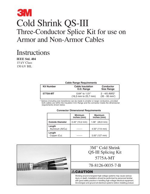
<strong>Cold</strong> <strong>Shrink</strong> <strong>QS</strong>-<strong>III</strong><br />
Three-Conductor Splice Kit for use on<br />
Armor and Non-Armor Cables<br />
Instructions<br />
IEEE Std. 404<br />
15 kV Class<br />
150 kV BIL<br />
Kit Number<br />
Cable Range Requirements<br />
Cable Insulation Conductor<br />
O.D. Range Size Range<br />
5775A-MT 0.64" to 1.01" 2 - 4/0 AWG*<br />
(16,3 mm to 25,7 mm) (35 - 95 mm 2 )<br />
* Splices (including size transitions) can be made to smaller or larger conductors, provided<br />
both cables are within the Insulation O.D. Range and the connector meets the dimensional<br />
requirements shown below.<br />
Connector Dimensional Requirements<br />
Minimum Maximum<br />
inches (mm) inches (mm)<br />
Outside Diameter 0.40" (10,2 mm) 1.06" (26,9 mm)<br />
Length<br />
Aluminum (Al/Cu)<br />
Length<br />
-------- 4.50" (114 mm)<br />
Copper (Cu) -------- 5.00" (127 mm)<br />
CAUTION<br />
<strong>3M</strong> <strong>Cold</strong> <strong>Shrink</strong><br />
<strong>QS</strong>-<strong>III</strong> Splicing Kit<br />
5775A-MT<br />
78-8126-0035-7-B<br />
Working around energized high-voltage systems may cause serious<br />
injury or death. Installation should be performed by personnel familiar<br />
with good safety practice in handling high-voltage electrical equipment.<br />
De-energize and ground all electrical systems before installing product.
Contents<br />
1.0 Kit Contents ............................................................................................................................................3<br />
2.0 Prepare Cable ..........................................................................................................................................3<br />
3.0 Place Components on Cable ..................................................................................................................5<br />
4.0 Install Splice ............................................................................................................................................6<br />
5.0 Install Armor Continuity (if cable is armored) ......................................................................................8<br />
6.0 Install Splice Jacket ................................................................................................................................9<br />
2<br />
78-8126-0035-7-B
1.0 Kit Contents:<br />
1.1 Kit Contents are as follows:<br />
3 ..............<strong>Cold</strong> <strong>Shrink</strong> 5415A <strong>QS</strong>-<strong>III</strong> Silicone Splice Bodies<br />
6 ..............Tubes, P55/R Red Compound<br />
3 ..............Metallic Shield Sleeves<br />
6 ..............Constant Force Spring Shield Connectors (0.68" I.D.)<br />
1 ..............Armor to Armor Continuity Braid<br />
2 ..............Constant Force Spring Braid Connectors (1.54" I.D.)<br />
2 ..............<strong>Cold</strong> <strong>Shrink</strong> Jacket Tubes<br />
1 ..............<strong>3M</strong> CC-2 Cable Preparation Kit<br />
1 ..............Roll, Scotch 33+ Vinyl Electrical Tape (3/4" x 66')<br />
2 ..............Rolls, Scotch Super 88 Vinyl Electrical Tape (1 1/2" x 44')<br />
1 ..............Roll, Scotch-Seal 2229 Mastic Tape (3 3/4" x 10')<br />
1 ..............Roll, Scotch 24 Electrical Shielding Tape (1" x 15')<br />
1 ..............Roll, Scotch 2228 Rubber Mastic Tape (2" x 10')<br />
3 ..............Rolls, Armorcast Structural Material (4" x 15')<br />
1 ..............Instruction Sheet<br />
6 ..............<strong>Cold</strong> <strong>Shrink</strong> Adapter Tubes<br />
6 ..............Copper Foil Tape (1/2" x 10")<br />
6 ..............Gloves<br />
2.0 Prepare Cable<br />
2.1 Prepare the cable according to your company's<br />
standard procedures. Allow cable ends to overlap as<br />
much as 10" (254 mm).<br />
Remove 26 1/2" (673 mm) of cable jacket, plus half<br />
of the overlap from Cable X.<br />
Remove 21 1/2" (546 mm) of cable jacket, plus half<br />
of the overlap from Cable Y.<br />
Keep a 16" (406 mm) piece of cable jacket removed<br />
from Cable X and an 11" (279 mm) piece of jacket<br />
from Cable Y for use later in these instructions.<br />
2.2 If cable is armored, remove cable armor leaving<br />
1 1/2” (37 mm) armor exposed beyond jacket end.<br />
Remove cable binder , if present, at the end of the<br />
jacket or armor and discard.<br />
Fold cable fillers and ground wire(s) back over<br />
cable jacket end. Do not cut off.<br />
Temporarily hold the fillers and ground wire(s) back<br />
by banding them to the cable jacket using Scotch 33+ vinyl tape included in kit.<br />
78-8126-0035-7-B<br />
3<br />
1 1/2"<br />
(37 mm)<br />
Cable X<br />
26 1/2"<br />
(673 mm)<br />
Cable Y<br />
21 1/2"<br />
(546 mm)<br />
remove<br />
binder fold fillers back<br />
DO NOT CUT OFF
2.3 Cut the phase conductors to the appropriate length.<br />
Conductors of Cable X should be 26 1/2” (673 mm)<br />
when measured from the cable jacket end or 25”<br />
(635 mm) when measured from end of the armor.<br />
Conductors of Cable Y should be 21 1/2” (546 mm)<br />
when measured from the cable jacket end or 20”<br />
(508 mm) when measured from end of the armor.<br />
2.4 Bind the metallic shields of both Cable X and<br />
Cable Y conductors with copper tape strip at a point<br />
9 3/4” (248 mm) from the end of each conductor.<br />
Remove the metallic shields to copper tape binding .<br />
If the conductors are individually jacketed, remove<br />
the individual jackets a distance of 12 3/4” (324 mm)<br />
from the end of each conductor.<br />
2.5 Remove cable semi-conductive insulation shields<br />
from conductors of both Cable X and Cable Y<br />
a distance of 6 3/4" (171 mm) from the end of each<br />
conductor.<br />
Note: Cables must be within Insulation OD Range of<br />
splice kit.<br />
2.6 Remove cable insulation from conductors ends of<br />
both Cable X and Cable Y.<br />
Remove cable insulation for 1/2 connector length plus<br />
an allowance * for increases in connector length due<br />
to crimping. Insulation removal length shall not<br />
exceed 2 1/2" (64 mm) from conductor end.<br />
Do not install connectors now.<br />
*Note: This assumes that the installer has determined<br />
the increased length of an aluminum connector<br />
crimped with a specific tool and die.<br />
Aluminum Typical Growth<br />
Connector Size allowance per end<br />
2 AWG 1/8" (3 mm)<br />
1 AWG 1/8" (3 mm)<br />
1/0 AWG 1/8" (3 mm)<br />
2/0 AWG 1/8" (3 mm)<br />
3/0 AWG 1/8" (3 mm)<br />
4/0 AWG 1/4" (6 mm)<br />
4<br />
copper<br />
tape strips<br />
Notes: 1) Copper connectors do not require a length change allowance.<br />
2) Maximum aluminum connector crimped length allowed is 5.00" (127 mm).<br />
Cable X 26 1/2" (673 mm)<br />
Cable Y 21 1/2" (546 mm)<br />
9 3/4" (248 mm)<br />
6 3/4" (171 mm)<br />
field determine<br />
78-8126-0035-7-B
3.0 Place Components on Cable<br />
3.1 Slide one large cold shrink jacket tube onto<br />
Cable X and one onto Cable Y with the loose<br />
core ribbon ends going on the cable last, extending<br />
toward the cable ends.<br />
3.2 Slide a cold shrink splice body onto each<br />
conductor of Cable X with the loose core ribbon<br />
end going on the cable first, away from cable end.<br />
3.3 Expand metallic shield sleeves and slide one onto<br />
each conductor of Cable Y. Compress the ends of<br />
each shield sleeve together next to the cable armor or<br />
jacket end, away from the prepared conductor ends.<br />
3.4 For 2 through 1/0 AWG copper connectors, 2 and<br />
1 AWG aluminum connectors, or connectors with<br />
an O.D. between 0.40–0.55" (10,2–14,0 mm): Slide<br />
the cold shrink adapter tube with the WHITE CORE<br />
onto the insulation of cable Y with the loose core<br />
ribbon end going on first, away from the cable end.<br />
78-8126-0035-7-B<br />
For 2/0 through 4/0 AWG copper connectors or<br />
connectors with an O.D. between 0.50–0.64"<br />
(12,7–16,3 mm): Slide the cold shrink adapter tube<br />
with the RED CORE onto the insulation of cables Y<br />
with the loose core ribbon end going on first, away<br />
from the cable end.<br />
5<br />
loose core<br />
ribbon end<br />
large jacket tube<br />
loose core ribbon end<br />
shield<br />
sleeve<br />
loose core ribbon end<br />
adapter tube<br />
splice body
4.0 Install Splice<br />
4.1 Install connectors. See Table on front cover of this<br />
instruction for proper connector dimensions. Crimp<br />
connectors per recommendations from connector<br />
manufacturer. For standard <strong>3M</strong> connectors, refer to<br />
table at the end of this instruction for crimping<br />
information.<br />
4.2 Apply a tape marker to cable semi-con insulation<br />
shields on Cable Y (cable side which does not<br />
contain splice body) at a distance of 8 1/2”<br />
(216 mm) measured from the CENTER of<br />
connectors.<br />
4.3 If using cold shrink adapter tube:<br />
Position cold shrink adapter tube over center of<br />
connector. <strong>Shrink</strong> the adapter near center of<br />
connector by pulling and unwinding in a counterclockwise<br />
direction.<br />
4.4 Remove any excess oxidation inhibitor from<br />
connector ends if aluminum connectors are used.<br />
Clean cable using standard practice:<br />
a. Do not use solvent or abrasive on cable<br />
semi-conductive insulation shield.<br />
b. If abrasive is used on cable insulation, do not<br />
reduce diameter below the 0.64" (16,3 mm)<br />
minimum specified for the splice.<br />
6<br />
8 1/2" (216 mm)<br />
78-8126-0035-7-B
4.5 Apply red compound on cable insulation, making<br />
certain to fill in edges of cable semi-con.<br />
Note: DO NOT use silicone grease.<br />
4.6 Individually, position each splice body over the<br />
connector area and align the leading end of the<br />
rubber with the center of the marker tape.<br />
Slowly begin to remove the inner support core by<br />
pulling while unwinding the loose ribbon end in a<br />
counterclockwise direction, allowing only 1/4”<br />
(6 mm) of the splice to shrink onto the marker tape.<br />
Carefully slide the splice body off the marker tape<br />
by pulling and twisting until the entire marker tape<br />
is exposed. Continue removing the core to complete<br />
splice body installation.<br />
Note: The splice body ends must overlap onto the<br />
semi-conducting layer of each cable by at least<br />
1/2" (12,7 mm).<br />
Note: DO NOT push the splice body towards the tape<br />
marker, as this may cause the end to roll under. If<br />
the end does roll under, DO NOT use sharp edged<br />
tools to pull it out as this could cut and damage<br />
the splice.<br />
4.7 Center the metallic shield sleeves over the splice<br />
bodies. Hand tighten sleeves from center of splices<br />
outward in both directions. Secure sleeves by<br />
applying 33+ vinyl tape bands at splice center and at<br />
each end.<br />
4.8 Connect sleeve ends to the cable metallic shield<br />
with a small constant force spring.<br />
Install each spring by unwrapping and rewrapping<br />
the spring around itself over the shield sleeve end and<br />
cable metallic shield.<br />
78-8126-0035-7-B<br />
Trim off excess shield sleeve braid material.<br />
Cover springs and trimmed shield sleeve ends with<br />
one half-lapped layer of vinyl tape.<br />
7<br />
Red P55/R<br />
compound<br />
align end of splice body to<br />
marker tape<br />
33+ vinyl tape<br />
trim off excess sleeve
4.9 Connect the ground wire(s) from Cable X to the<br />
ground wire(s)from Cable Y. Make the connection<br />
away from the splice bodies.<br />
4.10 Unfold the cable fillers and reestablish their lay<br />
between the cable conductors. Hold the fillers in<br />
place with a band of 33+ vinyl tape.<br />
5.0 Install Armor Continuity (If Cable is Armored)<br />
5.1 Apply multiple wraps of Scotch 24 shielding tape<br />
around the exposed armor on both Cable X and<br />
Cable Y to fill a valley in the corrugated armor. Half<br />
hitch to tie off.<br />
5.2 Wrap an end of the ground continuity braid around<br />
exposed armor and applied 24 tape on one cable end.<br />
Wrap one wrap only and fold the braid at 90° with<br />
the long braid end extending toward splice opening.<br />
Install a large constant force spring around the<br />
braid wrapped on the armor. Spiral wrap the braid<br />
around the splice opening to the other cable armor.<br />
Fold the braid 90° and wrap braid end around armor.<br />
Wrap braid end for one wrap only. Cut off and<br />
discard excess braid.<br />
Connect braid by installing other constant force<br />
spring. Overwrap each spring with 33+ tape.<br />
8<br />
connect ground wire(s)<br />
33+ vinyl tape<br />
constant<br />
force<br />
spring<br />
78-8126-0035-7-B
6.0 Install Splice Jacket<br />
6.1 Over wrap the exposed conductors on each side of<br />
splice bodies with jacket pieces saved from step 2.1.<br />
78-8126-0035-7-B<br />
Bind the cable jacket pieces in place with one<br />
half-lapped layer of Scotch 88, 1 1/2” wide tape.<br />
6.2 At both ends of splice, apply four wraps of 2228<br />
rubber mastic, around the cable jacket 1/2” from<br />
jacket ends.<br />
Stretch the rubber mastic to three-fourth original<br />
width when applying.<br />
6.3 Install a cold shrink jacket tube on each cable with<br />
the leading end just covering the 2228 mastic and the<br />
tube extending toward the splice bodies.<br />
Pull while unwinding the loose core ribbon end in<br />
a counterclockwise direction to install jacket tube.<br />
6.4 Apply one half lapped layer of 88 tape over the<br />
unjacketed area in splice center.<br />
9<br />
2228 rubber<br />
mastic<br />
cold shrink<br />
jacket tube<br />
overwrap jacket piece<br />
with vinyl tape<br />
88 vinyl<br />
tape
6.5 Apply two half-lapped layers of 4” wide 2229 tape<br />
over applied vinyl tape in splice center. Overlap ends<br />
of <strong>Cold</strong> <strong>Shrink</strong> jacket tubes 2” (51 mm).<br />
6.6 Cover the applied 2229 mastic with two half lapped<br />
layers of 88 tape.<br />
6.7 Overwrap the entire splice with a minimum of two<br />
half lapped layers of Armorcast wrap.<br />
Tear open the top end of the foil Armorcast material<br />
container and fill foil container half full with water.<br />
Squeeze the container four or five times allowing the<br />
water to penetrate the roll. Pour out water, remove<br />
roll from foil container and immediately apply to<br />
splice area.<br />
Bind the final wrap in place with vinyl tape.<br />
Note: Wear rubber gloves provided when handling<br />
Armorcast Wrap. The resin contains a<br />
black dye that will stain human skin.<br />
Armorcast Wrap can be applied first and then<br />
sprayed with water to activate the curing system<br />
It will also cure from moisture in the air in<br />
humid conditions.<br />
6.8 Splice is complete.<br />
10<br />
Armorcast <br />
wrap<br />
2229 mastic<br />
tape<br />
88 vinyl<br />
tape<br />
78-8126-0035-7-B
78-8126-0035-7-B<br />
Crimping Tool - Die Sets (number of crimps/end)<br />
Square D Co.<br />
<strong>3M</strong> Conductor Burndy Corporation Thomas & Betts Corp. Anderson Div. Kearney<br />
Connector Size<br />
No. (AWG or MD6 MY29 Y34A Y35, Y39 Y1000** TBM 5 TBM 8 TBM 15 VC6-3** Type O<br />
kcmil) Y45*, Y46* VC6-FT**<br />
CI-22 (Al/Cu) 2 sol. BG (3) --- U243 (1) U25ART (1) --- --- Olive(2) 50(1) (1) 5/8-1 (3)<br />
10003 (Cu) 2 str. W162(2) 2 AWG(1) A2CR(1) U2CRT(2) --- Brown(1) Brown(1) 33(1) (1) ---<br />
20003 (Al/Cu) 2 str. W163(3) 2AWG (1) A2CAB(1) UTCABT(1) (1) Pink(2) Pink(2) 42H(2) (1) 1/2 (3)<br />
CI-21 (Al/Cu) 2 str. BG (3) --- U243 (1) U25ART(1) --- --- Olive(2) 50(1) (1) 5/8-1 (3)<br />
10004 (Cu) 1 --- 1 AWG(1) A1CR(1) U1CRT(2) --- Green(1) Green(1) 37(1) (1) ---<br />
20004 (Al/Cu) 1 W163(3) 1AWG(1) A1CAB(1) U1CART(1) (1) Gold(2) Gold(2) 45(1) (1) 1/2 (3)<br />
CI-21 (Al/Cu) 1 BG (3) --- U243 (1) U25ART(1) --- --- Olive(2) 50(1) (1) 5/8-1 (3)<br />
10005 (Cu) 1/0 W163(2) 1/0(1) A25R(1) U25RT(1) --- Pink(2) Pink(2) 42(2) (1) ---<br />
20005 (Al/Cu) 1/0 W241(2) 1/0(1) A25AR(1) U25ART(1) (1) Tan(2) Tan(2) 50(1) (1) 5/8-1 (3)<br />
CI-1/0 (Al/Cu) 1/0 BG (3) --- U243 (1) U25ART(1) --- --- Olive(2) 50(1) (1) 5/8-1 (3)<br />
10006 (Cu) 2/0 W241(2) 2/0(1) A26R(1) U26RT(2) --- Black(2) Black(2) 45(1) (1) ---<br />
20006 (Al/Cu) 2/0 BG(4) 2/0(1) A26AR(2) U26ART(2) (1) Olive(2) Olive(2) 54H(2) (2) 5/8-1 (3)<br />
11006 (Cu) 2/0 W241(3) 2/0(2) A26R(2) U26RT(2) --- Black(3) Black(3) 45(2) (2) ---<br />
CI-2/0 (Al/Cu) 2/0 W249(3) --- --- U28ART(2) --- --- Blue(4) 76(2) (2) 840 (4)<br />
10007 (Cu) 3/0 W243(2) 3/0(1) A27R(1) U27RT(2) --- Orange(2) Orange(2) 50(1) (1) ---<br />
20007 (Al/Cu) 3/0 W166(4) 3/0(1) --- U27ART(2) (1) Ruby(2) Ruby(2) 60(2) (2) 737 (3)<br />
11007 (Cu) 3/0 W243(3) 3/0(2) A27R(2) U27RT(3) --- Orange(3) Orange(3) 50(2) (2) ---<br />
CI-3/0 (Al/Cu) 3/0 W249(3) --- --- U28ART(2) --- --- Blue(4) 76(2) (2) 840 (4)<br />
10008 (Cu) 4/0 BG(3) 4/0(1) A28R(2) U28RT(2) --- Purple(2) Purple(2) 54H(2) (2) ---<br />
20008 (Al/Cu) 4/0 W660(4) 4/0(2) A26AR(2) U28ART(2) (1) --- White(4) 66(4) (2) 840 (4)<br />
11008 (Cu) 4/0 BG(4) 4/0(2) A28R(3) U28RT(3) --- Purple(3) Purple(3) 54H(3) (3) ---<br />
CI-4/0 (Al/Cu) 4/0 W249(3) --- --- U28ART(2) --- --- Blue(4) 76(2) (2) 840 (4)<br />
*Y45 and Y46 accept all Y35 dies (“U Series”). For Y45, use PT6515 adapter. For Y46, use PUADP adapter.<br />
**Anderson VC6-3, VC6-FT and Burndy Y1000 require no die set.<br />
11
Armorcast , Scotch , Scotch-Seal , and <strong>3M</strong> are trademarks of <strong>3M</strong> Company.<br />
Note: The core material being removed from the Splice Body, Jacket Tubes<br />
and adapter are mixed polymers and can be recycled with other waste.<br />
Important Notice<br />
Before using this product, you must evaluate it and determine if it is suitable for your intended application. You assume all risks and liability<br />
associated with such use.<br />
Warranty; Limited Remedy; Limited Liability. This product will be free from defects in material and manufacture as of the date of<br />
purchase. <strong>3M</strong> MAKES NO OTHER WARRANTIES INCLUDING, BUT NOT LIMITED TO, ANY IMPLIED WARRANTY OF<br />
MERCHANTABILITY OR FITNESS FOR A PARTICULAR PURPOSE. If this product is defective within the warranty period stated above,<br />
your exclusive remedy shall be, at <strong>3M</strong>’s option, to replace or repair the <strong>3M</strong> product or refund the purchase price of the <strong>3M</strong> product.<br />
Except where prohibited by law, <strong>3M</strong> will not be liable for any loss or damage arising from this <strong>3M</strong> product, whether direct,<br />
indirect, special, incidental or consequential regardless of the legal theory asserted.<br />
Electrical Products Division<br />
6801 River Place Blvd.<br />
Austin, TX 78726-9000<br />
http://www.<strong>3M</strong>.com/electrical<br />
Printed on 50% recycled paper with<br />
10% post-consumer<br />
Printed in USA<br />
© <strong>3M</strong> 2002 78-8126-0035-7-B