GPU-accelerated Path Rendering - Nvidia
GPU-accelerated Path Rendering - Nvidia
GPU-accelerated Path Rendering - Nvidia

You also want an ePaper? Increase the reach of your titles
YUMPU automatically turns print PDFs into web optimized ePapers that Google loves.
<strong>GPU</strong>-<strong>accelerated</strong> <strong>Path</strong> <strong>Rendering</strong><br />
Mark J. Kilgard Jeff Bolz<br />
NVIDIA Corporation ∗<br />
Computer Graphics Proceedings, Annual Conference Series, 2012<br />
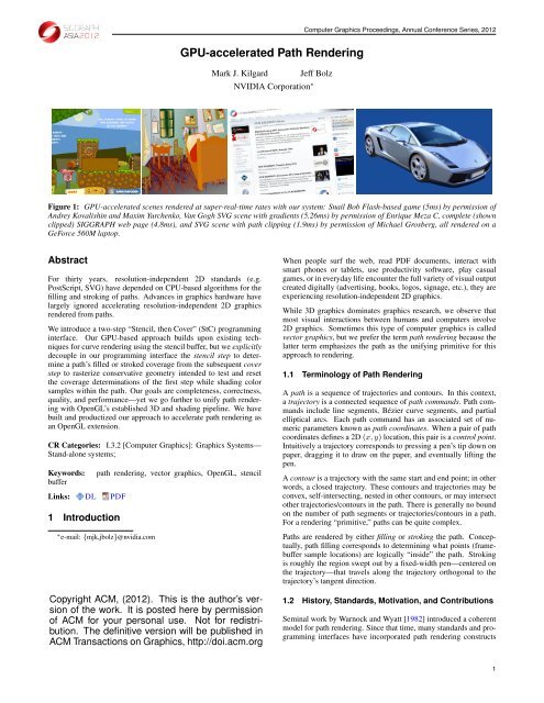
Figure 1: <strong>GPU</strong>-<strong>accelerated</strong> scenes rendered at super-real-time rates with our system: Snail Bob Flash-based game (5ms) by permission of<br />
Andrey Kovalishin and Maxim Yurchenko, Van Gogh SVG scene with gradients (5.26ms) by permission of Enrique Meza C, complete (shown<br />
clipped) SIGGRAPH web page (4.8ms), and SVG scene with path clipping (1.9ms) by permission of Michael Grosberg, all rendered on a<br />
GeForce 560M laptop.<br />
Abstract<br />
For thirty years, resolution-independent 2D standards (e.g.<br />
PostScript, SVG) have depended on CPU-based algorithms for the<br />
filling and stroking of paths. Advances in graphics hardware have<br />
largely ignored accelerating resolution-independent 2D graphics<br />
rendered from paths.<br />
We introduce a two-step “Stencil, then Cover” (StC) programming<br />
interface. Our <strong>GPU</strong>-based approach builds upon existing techniques<br />
for curve rendering using the stencil buffer, but we explicitly<br />
decouple in our programming interface the stencil step to determine<br />
a path’s filled or stroked coverage from the subsequent cover<br />
step to rasterize conservative geometry intended to test and reset<br />
the coverage determinations of the first step while shading color<br />
samples within the path. Our goals are completeness, correctness,<br />
quality, and performance—yet we go further to unify path rendering<br />
with OpenGL’s established 3D and shading pipeline. We have<br />
built and productized our approach to accelerate path rendering as<br />
an OpenGL extension.<br />
CR Categories: I.3.2 [Computer Graphics]: Graphics Systems—<br />
Stand-alone systems;<br />
Keywords: path rendering, vector graphics, OpenGL, stencil<br />
buffer<br />
Links: DL PDF<br />
1 Introduction<br />
∗ e-mail: {mjk,jbolz}@nvidia.com<br />
Copyright ACM, (2012). This is the author’s version<br />
of the work. It is posted here by permission<br />
of ACM for your personal use. Not for redistribution.<br />
The definitive version will be published in<br />
ACM Transactions on Graphics, http://doi.acm.org<br />
When people surf the web, read PDF documents, interact with<br />
smart phones or tablets, use productivity software, play casual<br />
games, or in everyday life encounter the full variety of visual output<br />
created digitally (advertising, books, logos, signage, etc.), they are<br />
experiencing resolution-independent 2D graphics.<br />
While 3D graphics dominates graphics research, we observe that<br />
most visual interactions between humans and computers involve<br />
2D graphics. Sometimes this type of computer graphics is called<br />
vector graphics, but we prefer the term path rendering because the<br />
latter term emphasizes the path as the unifying primitive for this<br />
approach to rendering.<br />
1.1 Terminology of <strong>Path</strong> <strong>Rendering</strong><br />
A path is a sequence of trajectories and contours. In this context,<br />
a trajectory is a connected sequence of path commands. <strong>Path</strong> commands<br />
include line segments, Bézier curve segments, and partial<br />
elliptical arcs. Each path command has an associated set of numeric<br />
parameters known as path coordinates. When a pair of path<br />
coordinates defines a 2D (x, y) location, this pair is a control point.<br />
Intuitively a trajectory corresponds to pressing a pen’s tip down on<br />
paper, dragging it to draw on the paper, and eventually lifting the<br />
pen.<br />
A contour is a trajectory with the same start and end point; in other<br />
words, a closed trajectory. These contours and trajectories may be<br />
convex, self-intersecting, nested in other contours, or may intersect<br />
other trajectories/contours in the path. There is generally no bound<br />
on the number of path segments or trajectories/contours in a path.<br />
For a rendering “primitive,” paths can be quite complex.<br />
<strong>Path</strong>s are rendered by either filling or stroking the path. Conceptually,<br />
path filling corresponds to determining what points (framebuffer<br />
sample locations) are logically “inside” the path. Stroking<br />
is roughly the region swept out by a fixed-width pen—centered on<br />
the trajectory—that travels along the trajectory orthogonal to the<br />
trajectory’s tangent direction.<br />
1.2 History, Standards, Motivation, and Contributions<br />
Seminal work by Warnock and Wyatt [1982] introduced a coherent<br />
model for path rendering. Since that time, many standards and programming<br />
interfaces have incorporated path rendering constructs<br />
1
ACM SIGGRAPH 2012, Singapore, November 28–December 1, 2012<br />
into their 2D graphics framework. Without being exhaustive, we<br />
note<br />
• document presentation and printing: PostScript [Adobe Systems<br />
1985], PDF [Adobe Systems 2008a]<br />
• font specification: PostScript fonts [Adobe Systems 1992]<br />
• immersive web: Flash [Adobe Systems 2008b], HTML 5’s<br />
Scalable Vector Graphics [SVG Working Group 2011a]<br />
• 2D programming interfaces: OpenVG [Khronos Group 2008]<br />
• productivity software: Illustrator, Photoshop, Office<br />
Despite path rendering’s 30 year heritage and broad adoption, it<br />
has not benefited from acceleration by graphics hardware to anywhere<br />
near the extent 3D graphics has. Most path rendering today is<br />
performed by the CPU with sequential algorithms, not particularly<br />
different from their formulation 30 years ago. Our motivation is to<br />
harness existing <strong>GPU</strong>s to improve the overall experience achievable<br />
with path rendering.<br />
We present a productized system for <strong>GPU</strong>-<strong>accelerated</strong> path rendering<br />
in the context of the OpenGL graphics system; see some of our<br />
rendering results in Figure 1. Our system works on the three mostrecent<br />
architectural generations of GeForce and Quadro <strong>GPU</strong>s—<br />
and we expect all recent <strong>GPU</strong>s can support the algorithms and programming<br />
interface we describe.<br />
The primary contributions delivered by our system are:<br />
• A novel ”stencil, then cover” programming interface for path<br />
rendering, well-suited to acceleration by <strong>GPU</strong>s.<br />
• Our programming interface’s efficient implementation within<br />
the OpenGL graphics system to avoid CPU bottlenecks.<br />
• Accompanying algorithms to handle tessellation-free stenciled<br />
stroking of paths, standard stroking embellishments such<br />
as dashing, clipping paths to arbitrary paths, and mixing 3D<br />
and path rendering.<br />
Section 2 reviews prior path rendering systems. Section 3 explains<br />
our approach; we cite the crucial prior research that our approach<br />
integrates in this section. Section 4 compares our quality and<br />
performance to other implementations and highlights our system’s<br />
novel ability to mix with 3D and <strong>GPU</strong>-shaded rendering. Section 5<br />
discusses opportunities for future work.<br />
1.3 New Demands on <strong>Path</strong> <strong>Rendering</strong><br />
Historically, applications mostly “pre-render” 2D content specified<br />
with paths into bitmaps for glyphs and icons/images for vector artwork,<br />
then cache and blit those rasterized results as needed. <strong>Rendering</strong><br />
directly from the path data generally proved too slow to be<br />
viable. Early window systems based on path rendering concepts<br />
such as Sun’s NeWS [Gosling et al. 1989] and Adobe’s Display<br />
PostScript [Adobe Systems 1993] were arguably overly ambitious<br />
in basing their 2D rendering model around path rendering rather<br />
than resolution-dependent 2D bitmap rendering as did the more<br />
successful GDI and X11-based systems that proved easier for 2D<br />
graphics hardware to accelerate.<br />
1.3.1 Increasing Screen Density and Resolution<br />
Smart phones and tablets have created new platforms free from<br />
legacy display limitations such as relatively low—by today’s available<br />
technology—display density (measured in dots-per-inch or<br />
2<br />
DPI) and the dated visual appearance established by resolutiondependent<br />
bitmap graphics. Apple’s new iPad display has a display<br />
density of 264 DPI, greatly surpassing the 100 DPI density<br />
norm for PC screens. These handheld devices are carried directly<br />
on one’s person so their screen real estate is relatively fixed—so improvements<br />
in display appearance is likely to be through increasing<br />
screen density rather than enlarging screen area.<br />
Pixel resolutions for conventional monitors are increasing too.<br />
Large 2560x1600 resolution screens are mass-produced and readily<br />
available. Driving such high resolutions with CPU-based path rendering<br />
schemes is untenable at real-time rates. Indeed the very heterogeneity<br />
of modern displays in terms of pixel resolution, screen<br />
size, and their combination—pixel density—strengthens the case<br />
for improving path rendering performance.<br />
1.3.2 Multi-touch Interfaces<br />
Mobile devices also rely on multi-touch screens for input so the<br />
user is extremely aware of the latency between touch gestures and<br />
the resulting screen update. The user is literally pointing at the<br />
pixels they expect to see updated. Multi-touch encourages rotation<br />
and scaling. When imagery can easily be rotated, scaled, sub-pixel<br />
translated, and even projected, assumptions that all text and graphics<br />
will be orthographically aligned to the screen’s pixel grid are<br />
no longer a given so rendering all path content directly from paths<br />
makes sense.<br />
1.3.3 Immersive Web Standards<br />
The proximate HTML 5 web standard exposes path rendering functionality<br />
in a standard and pervasive way through both Scalable<br />
Vector Graphics (SVG) and the Canvas element.<br />
JavaScript performance has increased to the point that dynamic content<br />
can be orchestrated within a standards-based HTML 5 web<br />
page such that the system’s path rendering performance is often<br />
a bottleneck.<br />
1.3.4 Power Wall<br />
Minimizing power consumption has become a mantra for computer<br />
system design across all classes of devices—whether mobile<br />
devices or not. When power is at a premium, moving CPUand<br />
bandwidth-intensive computations such as pixel manipulation<br />
and rasterization to more power-efficient <strong>GPU</strong> circuitry can reduce<br />
overall power consumption while improving interactivity and minimizing<br />
update latency. <strong>GPU</strong>-acceleration of path rendering is precisely<br />
such an opportunity.<br />
2 Prior <strong>Path</strong> <strong>Rendering</strong> Systems<br />
2.1 CPU-based <strong>Path</strong> <strong>Rendering</strong> Systems Critiqued<br />
<strong>Path</strong> rendering is historically and still typically performed by CPUbased<br />
scan line renderers. <strong>Path</strong>s are converted into a set of edges.<br />
These edges are transformed and sorted in Y-order. Then the edges<br />
are intersected with each scan line, sorted in X-order, and pixels in<br />
the path region are updated.<br />
The scan-line rendering approach is notable for being workefficient<br />
and cache-friendly. No computation is expended on pixels<br />
that are obviously outside the path and only active edges are considered<br />
when processing a given scan line. Such scan line renderers<br />
use a “chunker” strategy—where rather than the chunk being<br />
a 2D tile, the chunk is a single scan line. This leads to a reasonably<br />
friendly access pattern for CPU caches. Additionally the scan
Computer Graphics Proceedings, Annual Conference Series, 2012<br />
Figure 2: Performance ratios rendering SVG content at window resolutions from 100 2 to 1100 2 . A ratio of 1.0 means the<br />
NV path rendering (16 samples per pixel) performance is equal to the other renderer; higher ratios indicate how many multiples faster<br />
NV path rendering is than the alternative. Note the logarithmic Y axis. Scenes were selected for their variety. Benchmark configuration<br />
is a GeForce 650 and fast Core i7 CPU.<br />
line enter/leave counts are transient. In contrast to a window-sized<br />
ancillary buffer such as a depth or stencil buffer, the scan line enter/leave<br />
counts can live in the cache and have their storage recycled<br />
for each processed scan line.<br />
While work-efficient and cache-friendly as noted, this CPUintensive<br />
approach is quite sequential. Every path must be transformed<br />
into screen space. Every path must be scan line rasterized.<br />
Every scan line must be intersected with the active edge list. Every<br />
sorted active edge list must be scanned left-to-right. There is not an<br />
easy way to pipeline all these tasks or exploit massive parallelism—<br />
such as is routine for <strong>GPU</strong>-<strong>accelerated</strong> 3D graphics. Hence this is<br />
an approach that maps well to the CPU but cannot be obviously<br />
<strong>accelerated</strong> in this form by the <strong>GPU</strong>.<br />
2.2 <strong>GPU</strong>-based <strong>Path</strong> <strong>Rendering</strong> Systems<br />
Over the years, many attempts have been made—with varying degrees<br />
of mixed success—to accelerate path rendering with <strong>GPU</strong>s.<br />
We postpone discussion of prior techniques for <strong>GPU</strong> rendering of<br />
curves with the stencil buffer to Section 3 since they are the basis<br />
for our approach.<br />
2.2.1 Acceleration of <strong>Path</strong> <strong>Rendering</strong> Programming Interfaces<br />
Cairo [Packard and Worth 2003] is an open-source path rendering<br />
implementation. An early attempt at <strong>GPU</strong>-acceleration called Glitz<br />
[Nilsson and Reveman 2004] has since been abandoned. Glitz operated<br />
at the level of the XRender [Packard 2001] extension so did not<br />
accelerate paths directly. Arguably, Glitz was a more <strong>GPU</strong>-assisted<br />
back-end than <strong>GPU</strong> <strong>accelerated</strong>. More recently, Cairo has worked<br />
on a first-class <strong>GPU</strong> back-end but the immediate mode nature of<br />
the Cairo API and converting CPU-transformed paths to spans limits<br />
the acceleration opportunities.<br />
Microsoft’s Direct2D [Kerr 2009] API is layered upon Direct3D.<br />
Direct2D operates by transforming paths on the CPU and then performing<br />
a constrained trapezoidal tessellation of each path. The<br />
result is a set of pixel-space trapezoids and additional shaded geometry<br />
to compute fractional coverage for the left and right edges of<br />
the trapezoids. These trapezoids and shaded geometry are then rasterized<br />
by the <strong>GPU</strong>. The resulting performance is generally better<br />
than entirely CPU-based approaches and requires no ancillary storage<br />
for multisample or stencil state; Direct2D renders directly into<br />
an aliased framebuffer with properly antialiased results. Direct2D’s<br />
primary disadvantage is the ultimate performance is determined not<br />
by the <strong>GPU</strong> (doing fairly trivial rasterization) but rather by the CPU<br />
performing the transformation and trapezoidal tessellation of each<br />
path and Direct3D validation work.<br />
Skia is the C++ path rendering API used by Google’s Android and<br />
Chrome browsers. Skia has a conventional CPU-based path renderer<br />
but has recently integrated a new OpenGL ES2-<strong>accelerated</strong><br />
back-end called Ganesh. Ganesh has experimented with two <strong>accelerated</strong><br />
approaches. The first used the stencil buffer to render paths.<br />
Because of API overheads with this approach, this first approach<br />
was replaced with a second approach where the CPU-based rasterizer<br />
computes a coverage mask which is loaded as a texture upon<br />
every path draw to provide the <strong>GPU</strong> proper antialiased coverage.<br />
This hybrid scheme is often bottlenecked by the dynamic texture<br />
updates required for every rendered path.<br />
The Khronos standards body worked to develop an API standard<br />
known as OpenVG with the explicit goal of enabling hardwareacceleration<br />
of path rendering (the VG stands for vector graphics).<br />
Various companies and research groups have worked to develop<br />
OpenVG hardware designs [FreeScale, Multimedia Applications<br />
Division 2010; Huang and Chae 2006; Kim et al. 2008] that,<br />
based on available descriptions, are fairly similar to the conventional<br />
CPU-based scan line rasterizer scheme, recast as a hardware<br />
unit. Reported performance levels are quite low compared to what<br />
we report.<br />
3
ACM SIGGRAPH 2012, Singapore, November 28–December 1, 2012<br />
2.2.2 Vector Texture Schemes<br />
An unconventional approach to <strong>GPU</strong>-accelerating path rendering is<br />
cleverly encoding path content into <strong>GPU</strong> memory—typically as a<br />
texture—and then using a programmable shader essentially to decode<br />
the path content. Nehad and Hoppe [2008] and Qin [2009]<br />
adopt variations on this approach. While this approach has some<br />
interesting advantages such as being able to directly “texture map”<br />
3D geometry with path rendered content, these approaches suffer<br />
from the need to preprocess a static path scene into a specific texture<br />
encoding. This makes this approach unsuitable for editable or<br />
dynamic path rendering. Additionally, many rendering approximations<br />
and authoring limitations are needed to make vector texture<br />
schemes tractable.<br />
2.2.3 Discussion of Deficiencies<br />
The norm for CPU-based path rendering systems is maintaining<br />
roughly 16 coverage samples per pixel (details vary). This creates<br />
a challenge for <strong>GPU</strong>-based schemes because <strong>GPU</strong>s often support<br />
1, 2, 4, or 8 samples per pixel through multisampling. This often<br />
creates a situation where the <strong>GPU</strong>-<strong>accelerated</strong> path rendering is inferior<br />
to the CPU-based path rendering quality.<br />
When path rendering schemes are layered upon existing OpenGL<br />
or Direct3D APIs, we have observed performance being limited by<br />
the state change rate of the underlying 3D API. Often path rendering<br />
can result in many state changes per path when scenes can easily<br />
consist of 100s or 1000s of paths. In this case, the API overhead can<br />
substantially limit the overall performance. Our experience studying<br />
prior approaches to using <strong>GPU</strong>s for path rendering indicates<br />
these approaches are often more <strong>GPU</strong>-assisted rather than <strong>GPU</strong><strong>accelerated</strong>,<br />
with this attributable to continuous CPU involvement<br />
or substantial CPU-based preprocessing.<br />
3 Our Approach<br />
In contrast to other systems for accelerating path rendering with<br />
<strong>GPU</strong>s, our approach explicitly reveals the coverage determinations.<br />
These determinations—for both filling and stroking—appear as<br />
stencil buffer updates. A crucial insight underlying our approach<br />
is never determining the boundary between the “inside” and “outside”<br />
of a stroke or fill. Instead, we rely on point-sampled determinations<br />
of whether a particular (x, y) framebuffer location is inside<br />
or outside the stroke or fill. For antialiasing, we rely on <strong>GPU</strong> multisampling<br />
to provide multiple sample coverage positions, each with<br />
its own sub-pixel stencil value.<br />
3.1 Stencil, then Cover<br />
We perform path rendering in two steps. This is not unique; all<br />
path rendering schemes involve two steps. The two steps may be<br />
“tessellate, then render tessellation” [Kerr 2009] or “intersect with<br />
scan line, then paint pixels” [Packard and Worth 2003] or “ray cast,<br />
then shade” [Nehab and Hoppe 2008] but each rendering of a path<br />
is inherently sequential in the sense that determining what pixels<br />
are covered must precede shading and blending those pixels.<br />
What is novel in our approach is explicitly decoupling the two steps.<br />
We call our approach, with its two decoupled steps, “Stencil, then<br />
Cover” (StC). Rather than a single Draw<strong>Path</strong> operation that hides<br />
the two-step nature of path rendering within the implementation, an<br />
OpenGL application using our extension first “stencils” the path in<br />
the stencil buffer [Akeley and Foran 1995], then “covers” the path<br />
to shade it.<br />
4<br />
This explicitly decoupled approach has advantages not available in<br />
interfaces that appear to offer a one-step Draw<strong>Path</strong> command.<br />
Our two-step approach makes arbitrary path clipping, mixing with<br />
3D graphics, programmable blend modes, and other novel path rendering<br />
usages possible.<br />
3.2 Filling<br />
3.2.1 Improvements to Prior Methods<br />
Our approach to filling paths is inspired by the work of Loop and<br />
Blinn [2005] who developed an efficient fragment shader-based approach<br />
to determining whether or not an (x, y) sample is inside or<br />
outside a given quadratic or cubic Bézier hull. In the Loop-Blinn<br />
formulation, inexpensive arithmetic on interpolated texture coordinates<br />
provides a Boolean predicate which when true indicates the<br />
fragment’s sample position is not inside the Bézier region.<br />
Our approach is not the first time the stencil buffer has been utilized<br />
for stenciling paths. Kokojima et al. [2006] applied the Loop-<br />
Blinn scheme in conjunction with the stencil buffer to determine<br />
the winding number of TrueType glyph outlines. Kokojima et al.<br />
showed the general filled polygon algorithm of Lane et al. [1983]—<br />
subsequently popularized for use with the stencil buffer [Neider<br />
et al. 1993]—can naturally combine with the Loop-Blinn quadratic<br />
discard shader to determine the samples inside an arbitrarily complex<br />
TrueType outline. After stenciling each glyph into the stencil<br />
buffer, conservative geometry based on a convex hull or bounding<br />
box can test against the non-zero stencil values, shade those samples,<br />
and reset the stencil values back to an initial zero state.<br />
Kokojima’s approach does not immediately extend to cubic Bézier<br />
segments because the inside region within a cubic Bézier hull is<br />
not necessarily convex. Rueda et al. [2008] addressed this by providing<br />
simple topological strategies to subdivide cubic Bézier hulls<br />
using Bézier subdivision to guarantee convexity, but used an overly<br />
expensive discard fragment shader based on Bézier normalization<br />
rather than applying the Loop-Blinn cubic formulation.<br />
Our approach to handling cubic Bézier segments builds on all this<br />
work by combining cubic Bézier convex subdivision rules with the<br />
Loop-Blinn cubic formulation. We also perform the discard shaders<br />
at sample-rate rather than pixel-rate for improved coverage determinations<br />
and antialiasing. We use interpolation at explicit sample<br />
positions and our target <strong>GPU</strong>’s sample mask functionality to evaluate<br />
multiple samples within a pixel in a single shader instance.<br />
PostScript, SVG, and other standards support partial circular and<br />
elliptical arcs so an additional discard shader, expressed in Cg, handles<br />
these cases:<br />
void roundCoverage(float2 st : TEXCOORD0.CENTROID)<br />
{<br />
if (st.s*st.s + st.t*st.t > 1) discard;<br />
}<br />
with the (s, t) texture coordinates assigned so (0,0) is centered at<br />
the origin of roundness to discard samples outside the arc region<br />
contained in a sequence of one or more polygonal hulls bounding<br />
such arcs.<br />
3.2.2 Baked Form of Filled <strong>Path</strong>s<br />
In order to render a filled path, we “bake” the path into a resolutionindependent<br />
representation from which the path can be stenciled<br />
under arbitrary projective transforms. This baking process takes<br />
time linearly proportional to the number of path commands. The<br />
resulting baked path data resides completely on the <strong>GPU</strong>. The required<br />
<strong>GPU</strong> storage is also linearly proportional to the number of
Figure 3: Filled path, with control points, with anchor geometry,<br />
and with cubic Bézier discard hulls, and conservative cover geometry.<br />
path commands. For a static path, the baking process needs to be<br />
done just once; the baking process must be repeated if the path’s<br />
commands or coordinates change, but edits to the path, including<br />
insertions and deletions of commands, require just re-baking the<br />
path segments at or immediately adjacent to the edits.<br />
Once baked, a filled path is reduced to five sets of primitives:<br />
1. Polygonal anchor geometry (structured as triangle fans), rendered<br />
with no shader.<br />
2. Quadratic discard triangles, rendered with a Loop-Blinn<br />
quadratic discard shader.<br />
3. Cubic discard triangles (if the cubic Bézier hull is a triangle)<br />
and quadrilaterals, rendered with a Loop-Blinn cubic discard<br />
shader.<br />
4. Arc discard triangles, rendered with the roundCoverage<br />
discard shader shown above.<br />
5. Conservative covering geometry, typically a triangle fan or<br />
quadrilateral.<br />
Primitive sets #1 through #4 are rendered during the stencil fill<br />
step. Two-sided stencil testing increments non-discarded stencil<br />
samples of front-facing primitives; back-facing primitives instead<br />
decrement non-discarded stencil samples. Primitive set #5 is rendered<br />
during the cover fill step. Primitive sets #2 through #4 have<br />
properly assigned texture coordinates that drive each set’s respective<br />
discard shader. Figure 3 visualizes the baked anchor, discard,<br />
and cover geometry.<br />
This approach to path filling is theoretically sound because the<br />
stencil rendering reduces to a winding number computation consistent<br />
with a discrete formulation of Jordan’s Theorem [Fabris et al.<br />
1997].<br />
All the data for a baked path can be stored within a single allocation<br />
of <strong>GPU</strong> memory to minimize the expense of stenciling or<br />
covering the path. Because the baked representation is completely<br />
resolution-independent, robust, and entirely on the <strong>GPU</strong>, the CPU<br />
overhead to launch the stenciling and/or covering of an already<br />
baked path object is minimal.<br />
We implement our approach as an OpenGL extension named<br />
NV path rendering [Kilgard 2012]. Performing the stencil and<br />
cover steps within the graphics driver avoids the API and driver validation<br />
overhead (see Section 4.2) that plagued other <strong>GPU</strong>-based<br />
approaches. Figure 4 shows how our new path pipeline co-exists<br />
with the existing pipelines in OpenGL for pixel and vertex processing.<br />
Computer Graphics Proceedings, Annual Conference Series, 2012<br />
Figure 4: High-level data flow of OpenGL showing pixel, vertex,<br />
and new path pipelines.<br />
3.3 Stroking<br />
Our stroking approach operates similarly to our filling approach<br />
whereby we stencil, then cover stroked paths from a baked<br />
resolution-independent representation residing on the <strong>GPU</strong> that requires<br />
minimal CPU overhead to both stencil and cover.<br />
3.3.1 Quadratic Bézier Stroking<br />
Analytically determining the points contained by a stroke curved<br />
segment is not easy. The boundary of the stroked region of<br />
a quadratic Bézier corresponds to an offset curve. While the<br />
quadratic Bézier curve generating the offset curve is 2 nd order,<br />
the offset curve for this generating segment’s boundary is 6 th order<br />
[Salmon 1960]. This makes exactly determining an intersection<br />
with this boundary unfeasible, particularly within the execution<br />
context of a <strong>GPU</strong>’s fragment shader. The boundary becomes<br />
even more vexing for partial elliptical arcs and cubic Bézier segments.<br />
The boundary for a general cubic Bézier curve is 10 th order<br />
[Farouki and Neff 1990]!<br />
Quadratic Bézier Segment Point Containment Hence our approach<br />
involves simply determining if a given (x, y) point is inside<br />
or outside the stroked region of a quadratic Bézier segment. This<br />
can be reduced to solving a 3 rd order equation.<br />
A quadratic Bézier segment Q—defined by the segment’s three<br />
control points C0, C1, and C2—can converted to monomial form<br />
Q(t) = At 2 + Bt + C = 0 for t ∈ [0, 1]. A point P is judged<br />
within the stroke of Q when there is a parametric value s on Q such<br />
that Q ′ (s) · (P − Q(s)) = 0 and the squared distance between<br />
Q(s) and P is within the squared stroke radius. (The dot product<br />
of a quadratic function and the derivative of a quadratic function is<br />
3 rd order.) Intuitively this corresponds to finding the 1 or 3 points<br />
Q(s) with a tangent direction orthogonal to the segment connecting<br />
P and Q(s). Such solutions s will be local minima or maxima for<br />
the distance between P and points on Q so computing the squared<br />
distance d = (Q(s)−P )·(Q(s)−P ) for each solution s indicates<br />
if P is within the stroke of Q(t) for t ∈ [0, 1] when both s ∈ [0, 1]<br />
and d is less than or equal the square of half the path’s stroke width.<br />
Figure 5 visualizes this procedure.<br />
Solving the cubic equation at every rasterized sample is expensive,<br />
but the computation can be simplified somewhat. The cubic equation<br />
can be rearranged into an easier-to-solve depressed cubic [Cardano<br />
1545] of the form t 3 + G(x, y)t + H(x, y) = 0. While the<br />
5
ACM SIGGRAPH 2012, Singapore, November 28–December 1, 2012<br />
Figure 5: Visualization of points within and outside the stroked<br />
region of a quadratic Bézier segment and their basis for inclusion<br />
or not.<br />
Figure 6: Examples of concave (top row) and convex (bottom row)<br />
stroked quadratic Bézier segment hulls.<br />
coefficients G(x, y) and H(x, y) are different for every path-space<br />
(x, y) location, the functions G and H are linear in terms of (x, y)<br />
so a vertex shader can evaluate G(x, y) and H(x, y) at hull positions<br />
and exploit the <strong>GPU</strong>’s ability to interpolate linearly G and H<br />
at positions within the hull.<br />
Care is taken when an arrangement of quadratic Bézier control<br />
points is collinear, collocated, or very nearly so. In such cases,<br />
we demote the quadratic Bézier segment to its linear degenerate<br />
equivalent for robustness.<br />
Stroked Quadratic Segment Hull Construction To harness this<br />
approach for rendering, we construct a hull around the quadratic<br />
Bézier stroked segment. As shown in Figure 6, the hull is typically<br />
concave, consisting of seven vertices—though the hull may<br />
be convex when the quadratic stroke’s width is wide relative to its<br />
arc length. Ruf [2011] has addressed the problem of a tight bounding<br />
representation for quadratic strokes, but his approach involves<br />
parabolic edges with the assumption the CPU can evaluate such<br />
edges efficiently; for our purposes, we want a triangular decomposition<br />
of the hull suitable for <strong>GPU</strong> rasterization.<br />
While solving the cubic equation—even in depressed form—is expensive,<br />
we note that stroked regions are typically small and narrow<br />
in screen space so this expensive process is used sparingly in<br />
practice. Even when strokes are wide, the massively parallel nature<br />
of the <strong>GPU</strong> makes this approach quite fast. Most important to us,<br />
6<br />
once a quadratic stroke is “baked” for rendering, it can be rendered<br />
under an arbitrary linear transformation—including projection—<br />
without any further CPU re-processing. The hull vertices and their<br />
coefficients for G and H can be stored in <strong>GPU</strong> memory so that<br />
stencil-only rendering the quadratic stroke involves simply configuring<br />
the appropriate buffers, the appropriate vertex and fragment<br />
shader pair, and rendering the hull geometry of the quadratic stroke.<br />
Higher-order-than-Quadratic Stroking <strong>Path</strong> rendering standards<br />
incorporate cubic Bézier segments and partial elliptical arcs;<br />
these involve cubic and rational quadratic generating curves for rasterized<br />
offset curve regions. The direct evaluation approach applied<br />
to generating quadratic Bézier curves is not tractable.<br />
Instead we subdivide cubic Bézier segments and partial elliptical<br />
arcs into an approximating sequence of quadratic Bézier segments.<br />
To maintain a curved boundary appearance at all magnifications,<br />
our subdivision approach maintains G 1 continuity at<br />
quadratic Bézier segment boundaries. No matter how much you<br />
zoom into the boundary of higher-order stroked segments, there is<br />
never any sign of linear edges or even a false discontinuity in the<br />
curvature.<br />
Following the approach of Kim and Ahn [2009], we bound the subdivision<br />
such that the true higher-order generating curve never escapes<br />
a specified percentage threshold of the stroke width of the<br />
approximating quadratic stroke sequence. We also subdivide at<br />
key topological features, specifically points of self-intersection and<br />
minimum curvature.<br />
3.3.2 Stroking Embellishments<br />
Stroking of line segments, end caps, and joins is straightforward.<br />
Stroked line segments are drawn as stencil-only rectangles. Polygon<br />
caps (square and triangular) and joins (bevel and miter) are likewise<br />
drawn as stencil-only triangles. This geometry can be drawn<br />
without any fragment shader. Round caps and joins are drawn<br />
with the same roundCoverage stencil-only sample-rate discard<br />
shader (Section 3.2.1) used for partial circular and elliptical arcs<br />
for filling with the (s, t) texture coordinates assigned appropriately<br />
to discard samples outside the circular region of the round cap or<br />
join. The baking process for stroked paths includes generating the<br />
rectangles and triangles for line segment and polygonal caps and<br />
joins. Geometry for round caps and joins is generated along with<br />
the texture coordinates to drive the round coverage discard shader.<br />
3.3.3 Dashing<br />
Dashing is a feature of all major path rendering standards except<br />
Flash. Dashing complicates stroking by turning on and off the<br />
stroking along a path based on an application-specified repeating<br />
on-off pattern specified in units of arc length. Our stroke baking<br />
process applies the dash pattern while gathering the geometry for<br />
the stroked path. While complicated in its details, our dashing process<br />
is similar to other path rendering implementations in its highlevel<br />
structure. The primary difference is curved path segments are<br />
reduced to quadratic Bézier segments in our approach instead of<br />
line segments. Whereas the arc length computations in conventional<br />
path rendering systems typically involve recursive subdivision<br />
until the curved segment approximates a line segment, our approach<br />
can stop subdividing at quadratic Bézier segments. Unlike<br />
higher order curves, the arc length of a quadratic Bézier segment (a
segment of a parabola) has a closed form analytical solution:<br />
1<br />
0<br />
Qx(t) 2 + Qy(t) 2 dt =<br />
b+2<br />
ln(<br />
√ ac<br />
b+2 c+2 √ c(c+a+b) )(b2−4 ac)+2 (b+2 c) √ c(c+a+b)−2 b √ ac<br />
8c 3/2<br />
with copious common subexpressions and where a = B · B,<br />
b = 2B · C, and c = C · C. Our interest in this approach is<br />
our desire to minimize use of expensive recursive subdivision algorithms<br />
while baking stroked paths, particularly during dashing.<br />
Some numerical care must be taken to avoid negative square roots,<br />
negative logarithms, and division by zero, but these cases occur<br />
when quadratic segments are nearly linear.<br />
Our dashing approach results in a resolution-independent baked<br />
form of the dashed stroked path. Once dashed and baked, no further<br />
CPU-based processing is necessary to render dashed paths. This<br />
is in contrast to other implementations of dashed stroking where<br />
dashing has a considerable CPU processing expense during rendering.<br />
While our implementation must of course represent each<br />
segment resulting from dashing, our render-time algorithm is completely<br />
oblivious to whether the original path was dashed.<br />
3.3.4 Baked Form of Stroked <strong>Path</strong>s<br />
Once baked, a stroked path is reduced to four sets of primitives:<br />
1. Polygonal geometry (line segments, bevel and miter joins,<br />
square and triangular end caps) with no shader.<br />
2. Triangle fans corresponding to quadratic Bézier segment hulls<br />
(curved path segments), rendered with a stroked quadratic discard<br />
shader.<br />
3. Triangle fans corresponding to round hulls (round end caps<br />
and joins) rendered with a round coverage shader.<br />
4. Conservative covering geometry, typically a triangle fan or<br />
quadrilateral.<br />
Primitive sets #1 through #3 are rendered during the stencil stroke<br />
step. Primitive set #4 is rendered during the cover stroke step.<br />
The REPLACE stencil operation used for stroking is order-invariant.<br />
Therefore we select a static rendering order during the baking process<br />
that minimizes <strong>GPU</strong> state changes during rendering.<br />
The geometry, texture coordinates, and per-hull quadratic discard<br />
shader coefficients are all packed into a single <strong>GPU</strong> buffer allocation.<br />
The rendering process for stenciling the baked path is very<br />
straightforward, requiring no more than three <strong>GPU</strong> state reconfigurations,<br />
one per primitive set above.<br />
The <strong>GPU</strong> storage for the linear and quadratic path segments in a<br />
baked stroked path is linearly proportional to the number of segments<br />
(post-dashing). For cubic Bézier segments and partial elliptical<br />
arcs, the storage depends on their required level of subdivision.<br />
Because this subdivision is tied to the stroke width, narrower stroke<br />
widths require more storage while wider stroke widths require less<br />
storage.<br />
3.4 Clipping to Arbitrary <strong>Path</strong>s<br />
All major path rendering standards support clipping a draw path to<br />
the filled region of a clip path. Our two-step “stencil, then cover”<br />
approach readily supports clipping to arbitrary paths. We briefly describe<br />
the process assuming an 8-bit stencil buffer, initially cleared<br />
to zero:<br />
Computer Graphics Proceedings, Annual Conference Series, 2012<br />
Figure 7: Complex clipping scenario. Our approach: 8.69ms @<br />
1000x1000x16. Cairo: 909ms @ 1000x1000. System: Core i7 +<br />
GeForce 560M <strong>GPU</strong>.<br />
1. Stencil the clip path into the stencil buffer with a “stencil fill”<br />
operation.<br />
2. Perform a “cover fill” operation to coalesce the samples<br />
matching the fill rule so that the most-significant stencil bit<br />
is set and all the lower bits are cleared. For example, if a sample’s<br />
stencil value is non-zero, replace the stencil value with<br />
0x80. This step updates only the stencil buffer (disable any<br />
color writes).<br />
3. Stencil the draw path into the stencil buffer with a “stencil<br />
fill” operation, but (a) modify only the bottom 7 bits of the<br />
stencil buffer, and (b) discard any rasterized samples without<br />
the topmost bit of the stencil buffer set.<br />
4. Perform a shaded “cover” operation on the draw path. Update<br />
any color sample whose stencil value’s bottom 7 bits are nonzero<br />
and zero the bottom 7 bits of the sample’s stencil value.<br />
Write shaded color samples during this step; due to the stencil<br />
configuration, only samples within both the clip and draw<br />
paths get shaded and updated.<br />
5. Finally to undo the clip path’s stencil manipulation from step<br />
1, perform a “cover” operation on the clip path to reset the<br />
most significant stencil bit back to zero.<br />
Many variations on this approach are possible. For example, steps<br />
3 and 4 can be repeated for each path in a layered group of paths.<br />
This avoids having to re-render the clip path for each and every path<br />
in a group of paths.<br />
Most standards allow nested clipping of paths to other paths. Clever<br />
manipulation of the stencil bit-planes allows such nested clipping.<br />
Standards such as SVG allow for clipping to the union of an arbitrary<br />
number of paths as shown in Figure 7. Again, we can accomplish<br />
this by clever use of stencil bit-planes and re-coalescing<br />
coverage from different clip paths.<br />
3.5 Painting<br />
What path rendering standards often call “painting” a filled or<br />
stroked path is called shading in 3D graphics. Our goal is to allow<br />
the full generality of <strong>GPU</strong>-based programmable shading to be<br />
exposed when painting paths.<br />
7
ACM SIGGRAPH 2012, Singapore, November 28–December 1, 2012<br />
Figure 8: Bump map shader applied to path rendered text, rendered<br />
from to different light positions, shown in yellow.<br />
During the cover step where a conservative bounding box or convex<br />
hull is rendered to cover fully the stenciling of the path, the<br />
application can configure arbitrary OpenGL shading. This could be<br />
fixed-function shading, assembly-level shaders, or shaders written<br />
in a high-level language such as Cg or GLSL.<br />
In conventional path rendering systems, linear and radial gradients<br />
are a common form of paint for paths. We note how straightforward<br />
radial gradient paint can be implemented, including mipmapped filtering<br />
of the lookup table accesses, with the following Cg shader:<br />
void radialFocalGradient(float3 str : TEXCOORD0.CENTROID,<br />
float4 c : COLOR.CENTROID,<br />
out float4 color : COLOR,<br />
uniform sampler1D ramp : TEXUNIT0)<br />
{<br />
color = c*tex1D(ramp, length(str.xy) + str.z);<br />
}<br />
The texture coordinates needed for this shader can be generated<br />
as a linear function of the path-space coordinate system. Painting<br />
need not be limited to conventional types of path rendering paint.<br />
Arbitrary fragment shader processing can be performed during the<br />
cover step (see Figure 8).<br />
3.6 Blending and Blend Modes<br />
OpenGL blending is sufficient for most path rendering where the<br />
default path compositing operation is the “over” blend mode, assuming<br />
pre-multiplied alpha. Color writes during our cover step<br />
apply the currently configured OpenGL blend state. Modern <strong>GPU</strong>s<br />
also have efficient first-class support for blending in the widelyused<br />
sRGB device color space.<br />
Sophisticated path rendering systems have additional blend modes<br />
[SVG Working Group 2011b] beyond the standard Porter-Duff<br />
compositing algebra [1984]. Digital artists are familiar with these<br />
modes with names such as ColorDodge, HardLight, etc. However<br />
<strong>GPU</strong> blending does not support these blend modes because they are<br />
rare, complex, and not used by 3D graphics. While some of these<br />
blend modes can be simulated with multiple rendering passes, many<br />
of these modes are impossible to construct from conventional <strong>GPU</strong><br />
blending operations.<br />
Our “stencil, then cover” approach makes it possible to implement<br />
these blend modes despite their lack of direct <strong>GPU</strong> hardware support.<br />
Normally, <strong>GPU</strong>s do not reliably support reading-as-a-texture<br />
a framebuffer currently being rendered. However a recent OpenGL<br />
extension called NV texture barrier [Bolz 2009] provides a<br />
reliable memory barrier under restrictive conditions. A fragment<br />
shader must ensure there is a single read and write for any particular<br />
pixel done from that pixel’s fragment shader instance.<br />
The “stencil, then cover” approach provides precisely such a “no<br />
double blending” guarantee. So by preceding each cover operation<br />
8<br />
Figure 9: Various path rendering implementations drawing a difficult<br />
cubic Bézier curve (the centurion head).<br />
(whether fill or stroke) with an OpenGL glTextureBarrierNV<br />
command and reading the pixel’s color value as a fetch to the framebuffer<br />
bound as a texture, reliable programmable blending with the<br />
fragment shader is possible.<br />
4 Discussion<br />
4.1 Quality<br />
Our system’s rendering quality is directly tied to how many color<br />
and stencil samples the framebuffer maintains per pixel. This determines<br />
the quality of our antialiasing. Our GeForce <strong>GPU</strong>s support<br />
up to 16 samples per pixel while our Quadro <strong>GPU</strong>s support 32 and<br />
64 samples per pixel as well.<br />
At 16 samples per pixel, our rendering quality compares quite favorably<br />
with CPU-based path renderers. Because our <strong>GPU</strong>s have<br />
8 bits of sub-pixel precision, irregular coverage sample positions,<br />
and our point containment determinations are numerically sound,<br />
we are well-justified in stating our quality exceeds what can reasonably<br />
be expected for CPU-based path renderers. We focus on<br />
two aspects of path rendering quality where our implementation<br />
has superior quality.<br />
4.1.1 Stroking Quality<br />
For stroking, our quadratic Bézier stroke discard shader is mathematically<br />
consistent with the sweep of an orthogonal pen traversing<br />
the path’s trajectory. In Figure 9 we compare our very fast<br />
stroking result to alternatives that are generally substantially slower<br />
on a difficult cubic Bézier stroke test case. Notice three path rendering<br />
implementation get this test case quite wrong—whereas<br />
NV path rendering matches the OpenVG reference implementation<br />
and Direct2D version.<br />
4.1.2 Conflation Avoidance<br />
Conflation is an artifact in path rendering systems that occurs when<br />
coverage (a Boolean concept) is conflated with opacity. This generally<br />
occurs when sub-pixel coverage is converted to a fractional<br />
value and multiplied into the alpha color component for compositing.<br />
While this approach is standard practice, it can result in noticeably<br />
incorrect colors.<br />
Conflation is particularly noticeable when two opaque paths exactly<br />
seam at a shared boundary. Say path A covers 40% of the pixel and<br />
an adjacent path B covers the other 60%. But if A is drawn first,
Figure 10: Flash scene with shared edges.<br />
NV path rendering shows no conflation while Direct2D<br />
(and Cairo, Skia, Qt, and OpenVG) shows conflation. Upper left<br />
corner shows the background clear color; conflation is tinted by<br />
this color in the bottom scenes. Notice the conflated blue tint on<br />
the girl’s cheek.<br />
the pixel picks up 40% of A’s color and 60% of the background<br />
color. Now when B is drawn, the pixel gets 60% of B’s color and<br />
40% of the combination of 40% of A’s color and 60% of the background<br />
color. The result is some fraction of the background color<br />
has leaked into the pixel when a more accurate assessment of coverage<br />
would have no background color.<br />
Flash content is particularly prone to conflation artifacts because<br />
path edges are typically authored for exact sharing of edges.<br />
Adobe’s Flash player specifically works to avoid conflation artifacts.<br />
This is possible because Flash player has complete knowledge<br />
of all the paths in a Flash shape and how those path edges<br />
are shared. Exact sharing of edges is helpful from a content creation<br />
standpoint because a shared edge can be stored once and<br />
used by two paths (more compact) and reduces the overall layered<br />
depth complexity of the scene by avoiding overlaps. Because<br />
NV path rendering maintains distinct sub-pixel color samples,<br />
the scene in Figure 10 renders free of conflation artifacts.<br />
4.2 Performance<br />
The rendering performance of NV path rendering scales with<br />
<strong>GPU</strong> performance. Because the baked paths reside on the <strong>GPU</strong><br />
and are resolution-independent, once baked, path rendering performance<br />
is decoupled from CPU performance. Figure 2 charts the<br />
performance of NV path rendering relative to alternatives—<br />
including <strong>GPU</strong>-<strong>accelerated</strong> alternatives such as Direct2D and<br />
Skia’s Ganesh approach.<br />
Our performance advantage is attributable to the overall rendering<br />
and shading performance of our underlying <strong>GPU</strong>s. Several aspects<br />
are particularly noteworthy. Our underlying <strong>GPU</strong>s support<br />
a fast stencil culling mode so hundreds of pixels can be culled in<br />
a single clock if a coarse grain test can determine the stencil test<br />
for all the pixels would fail. This mitigates much of what might<br />
otherwise seem very inefficient about the “stencil, then cover” approach.<br />
Also stencil processing generally is very well optimized.<br />
The 8-bit memory transactions during the stencil and cover steps<br />
can often run at memory bus saturating rates. Our OpenGL driver<br />
Computer Graphics Proceedings, Annual Conference Series, 2012<br />
Figure 11: Mixing 3D and path rendering in a single window.<br />
implementation makes use of a configurable front-end processor<br />
within the <strong>GPU</strong>—not otherwise accessible to applications—to transition<br />
quickly between the stencil step and cover step and back.<br />
This avoids the driver performing expensive revalidations of CPUmanaged<br />
state so our rendering stays <strong>GPU</strong>-limited rather than CPUbottlenecked,<br />
even when presented with otherwise overwhelming<br />
numbers of small paths.<br />
4.3 New Functionality<br />
Because NV path rendering is integrated into the OpenGL<br />
pipeline and the coverage information is accessible through the<br />
stencil buffer, we are able to implement unconventional algorithms<br />
such as mixing path rendering with arbitrary 3D graphics.<br />
Figure 11 demonstrates an example of this capability. No textures<br />
are used in this scene. Arbitrary zooming into the tigers’ detail is<br />
supported. Notice how the tigers properly occlude each other and<br />
the teapot. Due to the perspective 3D view, the path rendering is<br />
properly rendered in perspective as well.<br />
5 Future Work<br />
We believe our performance can be further improved. We are investigating<br />
hardware improvements to mitigate some of the memory<br />
bandwidth expense involved in our underlying stencil-based algorithms.<br />
In particular, we are seeking to reduce the <strong>GPU</strong> memory<br />
footprint.<br />
Web browser architecture should change to incorporate <strong>GPU</strong><strong>accelerated</strong><br />
path rendering. Today web browsers respecify paths<br />
every time a web page with path content is re-rendered assuming respecifying<br />
paths is cheap relative to the expense of rendering them.<br />
When path rendering is fully <strong>GPU</strong>-<strong>accelerated</strong>, a retained model<br />
of rendering is more appropriate and efficient. We believe web<br />
browsers should behave more like video games in this respect to<br />
exploit the <strong>GPU</strong>.<br />
Mobile devices are power constrained so off-loading path rendering<br />
to a graphics processor designed for efficient pixel processing<br />
makes good sense. Mobile devices in particular prize a low-latency<br />
experience for the user so the sooner the device can complete its<br />
resolution-independent 2D rendering, the better the user experience<br />
and the sooner the device can power down to a low power state.<br />
9
ACM SIGGRAPH 2012, Singapore, November 28–December 1, 2012<br />
Acknowledgements<br />
Michael Toksvig corrected Mark’s 3D bigotry and insisted 2D rendering<br />
deserved acceleration. Chris Dalton assisted building our<br />
test bed. Tero Karras provided crucial math insights. Barthold<br />
Lichtenbelt supported this work throughout.<br />
References<br />
ADOBE SYSTEMS. 1985. PostScript Language Reference Manual,<br />
1 st ed. Addison-Wesley Longman Publishing Co., Inc. 2<br />
ADOBE SYSTEMS. 1992. Adobe Type 1 Font Format, 2 nd ed.<br />
Addison-Wesley Longman Publishing Co., Inc. 2<br />
ADOBE SYSTEMS. 1993. Display PostScript System–Introduction:<br />
Perspective for Software Developers. 2<br />
ADOBE SYSTEMS. 2008. Document management–Portable document<br />
format–Part 1: PDF 1.7. Also published as ISO 3200.<br />
2<br />
ADOBE SYSTEMS. 2008. SWF File Format Specification, version<br />
10. 2<br />
AKELEY, K., AND FORAN, J., 1995. Apparatus and method for<br />
controlling storage of display information in a computer system.<br />
US Patent 5,394,170. 4<br />
BOLZ, J., 2009. NV texture barrier.<br />
http://www.opengl.org/registry/specs/NV/texture barrier.txt . 8<br />
CARDANO, G. 1545. Artis magnae sive de regulis algebraicis,<br />
liber unus. 5<br />
FABRIS, A., SILVA, L., AND FORREST, A. 1997. An efficient filling<br />
algorithm for non-simple closed curves using the point containment<br />
paradigm. In Proceedings of X Brazilian Symposium<br />
on Computer Graphics and Image Processing, 2 –9. 5<br />
FAROUKI, R., AND NEFF, C. 1990. Algebraic properties of plane<br />
offset curves. Computer Aided Geometric Design 7, 101–127. 5<br />
FREESCALE, MULTIMEDIA APPLICATIONS DIVISION. 2010.<br />
i.MX35 <strong>accelerated</strong> 2D graphics: Optimizing 2D graphics with<br />
OpenVG and i.MX35, application note, doc. # an3975. 3<br />
GOSLING, J., ROSENTHAL, D. S. H., AND ARDEN, M. J. 1989.<br />
The NeWS book: an introduction to the network/extensible window<br />
system. Springer-Verlag. 2<br />
HUANG, R., AND CHAE, S.-I. 2006. Implementation of an<br />
OpenVG rasterizer with configurable anti-aliasing and multiwindow<br />
scissoring. In Proceedings of the 6 th IEEE International<br />
Conference on Computer and Information Technology,<br />
IEEE Computer Society, CIT ’06, 179. 3<br />
KERR, K. 2009. Introducing Direct2D. MSDN Magazine (June).<br />
3, 4<br />
KHRONOS GROUP, 2008. OpenVG specification version 1.1. 2<br />
KILGARD, M., 2012. NV path rendering.<br />
http://www.opengl.org/registry/specs/NV/path rendering.txt . 5<br />
KIM, Y., AND AHN, Y. 2009. Explicit error bound for quadratic<br />
spline approximation of cubic spline. Journal of the Korean Society<br />
for Industrial and Applied Mathematics 13, 4, 257–265. 6<br />
KIM, D., CHA, K., AND CHAE, S.-I. 2008. A high-performance<br />
OpenVG accelerator with dual-scanline filling rendering. Consumer<br />
Electronics, IEEE Transactions on 54, 3 (August), 1303<br />
–1311. 3<br />
10<br />
KOKOJIMA, Y., SUGITA, K., SAITO, T., AND TAKEMOTO, T.<br />
2006. Resolution independent rendering of deformable vector<br />
objects using graphics hardware. In ACM SIGGRAPH 2006<br />
Sketches, SIGGRAPH ’06. 4<br />
LANE, J. M., MAGEDSON, R., AND RARICK, M. 1983. An algorithm<br />
for filling regions on graphics display devices. ACM Trans.<br />
Graph. 2, 3 (July), 192–196. 4<br />
LOOP, C., AND BLINN, J. 2005. Resolution independent curve<br />
rendering using programmable graphics hardware. In ACM SIG-<br />
GRAPH 2005 Papers, SIGGRAPH ’05, 1000–1009. 4<br />
NEHAB, D., AND HOPPE, H. 2008. Random-access rendering of<br />
general vector graphics. In ACM SIGGRAPH Asia 2008 papers,<br />
SIGGRAPH Asia ’08, 135:1–135:10. 4<br />
NEIDER, J., DAVIS, T., AND WOO, M. 1993. OpenGL Programming<br />
Guide, 1 st edition. See ”Drawing Filled, Concave Polygons<br />
Using the Stencil Buffer”, 398–399. 4<br />
NILSSON, P., AND REVEMAN, D. 2004. Glitz: hardware <strong>accelerated</strong><br />
image compositing using OpenGL. In Proceedings of the<br />
FREENIX Track: 2004 USENIX Annual Technical Conference,<br />
29–40. 3<br />
PACKARD, K., AND WORTH, C. 2003. A realistic 2D drawing<br />
system. A rejected SIGGRAPH 2003 paper submission. 3, 4<br />
PACKARD, K. 2001. Design and implementation of the X <strong>Rendering</strong><br />
Extension. In Proceedings of the FREENIX Track: 2001<br />
USENIX Annual Technical Conference, USENIX Association,<br />
213–224. 3<br />
PORTER, T., AND DUFF, T. 1984. Compositing digital images. In<br />
Proceedings of the 11 th annual Conference on Computer Graphics<br />
and Interactive Techniques, SIGGRAPH ’84, 253–259. 8<br />
QIN, Z. 2009. Vector Graphics for Real-time <strong>Rendering</strong>. PhD<br />
thesis. University of Waterloo. 4<br />
RUEDA, A. J., RUIZ DE MIRAS, J., AND FEITO, F. R. 2008. <strong>GPU</strong>based<br />
rendering of curved polygons using simplicial coverings.<br />
Computer Graphics 32, 5 (Oct.), 581–588. 4<br />
RUF, E. 2011. An inexpensive bounding representation for offsets<br />
of quadratic curves. In Proceedings of the ACM SIGGRAPH<br />
Symposium on High Performance Graphics, HPG ’11, 143–150.<br />
6<br />
SALMON, G. 1960. A Treatise on Conic Sections. Chelsea New<br />
York (reprint). 5<br />
SVG WORKING GROUP, 2011. Scalable Vector Graphics (SVG)<br />
1.1 (2 nd edition). 2<br />
SVG WORKING GROUP, 2011. SVG compositing specification.<br />
W3C working draft March 15, 2011. 8<br />
WARNOCK, J., AND WYATT, D. K. 1982. A device independent<br />
graphics imaging model for use with raster devices. In Proceedings<br />
of the 9 th Annual Conference on Computer Graphics and<br />
Interactive Techniques, SIGGRAPH ’82, 313–319. 1