

Steel Joists and joist Girders - New Millennium Building Systems
Steel Joists and joist Girders - New Millennium Building Systems
Steel Joists and joist Girders - New Millennium Building Systems

Create successful ePaper yourself
Turn your PDF publications into a flip-book with our unique Google optimized e-Paper software.
Introduction<br />
General Joist<br />
Information<br />
Economical<br />
Design Guide<br />
Top Chord<br />
Ext., K-Series<br />
KCS <strong>Joists</strong> Joist Substitutes<br />
& Outriggers<br />
Joist LRFD<br />
Load Tables<br />
Joist ASD<br />
Load Tables<br />
Load/Load<br />
Weight Tables<br />
Joist Girder<br />
Weight Tables<br />
SJI St<strong>and</strong>ard<br />
Specifications<br />
SJI Code of<br />
St<strong>and</strong>. Practice<br />
Fire Resistance<br />
Ratings<br />
OSHA Safety<br />
St<strong>and</strong>ards<br />
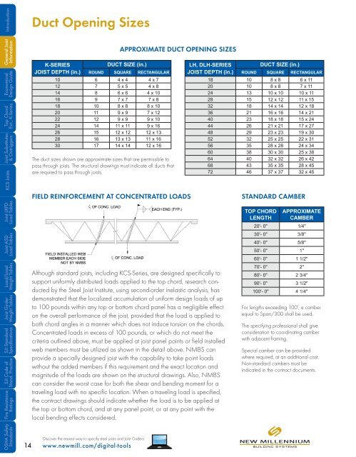
Duct Opening Sizes<br />
K-SERIES<br />
DUCT SIZE (in.)<br />
JOIST DEPTH (in.) ROUND SQUARE RECTANGULAR<br />
10 6 4 x 4 4 x 7<br />
12 7 5 x 5 4 x 8<br />
14 8 6 x 6 4 x 10<br />
16 9 7 x 7 7 x 8<br />
18 10 8 x 8 8 x 10<br />
20 11 9 x 9 7 x 12<br />
22 12 9 x 9 9 x 10<br />
24 14 11 x 11 9 x 16<br />
26 15 12 x 12 12 x 13<br />
28 16 13 x 13 11 x 16<br />
30 17 14 x 14 12 x 16<br />
The duct sizes shown are approximate sizes that are permissible to<br />
pass through <strong>joist</strong>s. The structural drawings must indicate all ducts that<br />
are required to pass through <strong>joist</strong>s.<br />
Discover the easiest way to specify steel <strong>joist</strong>s <strong>and</strong> Joist <strong>Girders</strong>:<br />
14 www.newmill.com/digital-tools<br />
APPROXIMATE DUCT OPENING SIZES<br />
FIELD REINFORCEMENT AT CONCENTRATED LOADS<br />
Although st<strong>and</strong>ard <strong>joist</strong>s, including KCS-Series, are designed specifically to<br />
support uniformly distributed loads applied to the top chord, research conducted<br />
by the <strong>Steel</strong> Joist Institute, using second-order inelastic analysis, has<br />
demonstrated that the localized accumulation of uniform design loads of up<br />
to 100 pounds within any top or bottom chord panel has a negligible effect<br />
on the overall performance of the <strong>joist</strong>, provided that the load is applied to<br />
both chord angles in a manner which does not induce torsion on the chords.<br />
Concentrated loads in excess of 100 pounds, or which do not meet the<br />
criteria outlined above, must be applied at <strong>joist</strong> panel points or field installed<br />
web members must be utilized as shown in the detail above. NMBS can<br />
provide a specially designed <strong>joist</strong> with the capability to take point loads<br />
without the added members if this requirement <strong>and</strong> the exact location <strong>and</strong><br />
magnitude of the loads are shown on the structural drawings. Also, NMBS<br />
can consider the worst case for both the shear <strong>and</strong> bending moment for a<br />
traveling load with no specific location. When a traveling load is specified,<br />
the contract drawings should indicate whether the load is to be applied at<br />
the top or bottom chord, <strong>and</strong> at any panel point, or at any point with the<br />
local bending effects considered.<br />
LH, DLH-SERIES<br />
DUCT SIZE (in.)<br />
JOIST DEPTH (in.) ROUND SQUARE RECTANGULAR<br />
18 10 8 x 8 6 x 11<br />
20 10 8 x 8 7 x 11<br />
24 13 10 x 10 10 x 11<br />
28 15 12 x 12 11 x 15<br />
32 18 14 x 14 12 x 18<br />
36 21 16 x 16 14 x 21<br />
40 23 18 x 18 15 x 24<br />
44 26 21 x 21 17 x 27<br />
48 29 23 x 23 19 x 30<br />
52 32 25 x 25 22 x 31<br />
56 35 28 x 28 24 x 34<br />
60 38 30 x 30 25 x 38<br />
64 40 32 x 32 26 x 42<br />
68 43 35 x 35 28 x 45<br />
72 46 37 x 37 32 x 45<br />
STANDARD CAMBER<br />
TOP CHORD<br />
LENGTH<br />
APPROXIMATE<br />
CAMBER<br />
20'- 0" 1/4"<br />
30'- 0" 3/8"<br />
40'- 0" 5/8"<br />
50'- 0" 1"<br />
60'- 0" 1 1/2"<br />
70'- 0" 2"<br />
80'- 0" 2 3/4"<br />
90'- 0" 3 1/2"<br />
100'- 0" 4 1/4"<br />
For lengths exceeding 100’, a camber<br />
equal to Span/300 shall be used.<br />
The specifying professional shall give<br />
consideration to coordinating camber<br />
with adjacent framing.<br />
Special camber can be provided<br />
where required, at an additional cost.<br />
Non-st<strong>and</strong>ard cambers must be<br />
indicated in the contract documents.

