building control guidance domestic loft conversions - Forest of Dean ...
building control guidance domestic loft conversions - Forest of Dean ...
building control guidance domestic loft conversions - Forest of Dean ...

Create successful ePaper yourself
Turn your PDF publications into a flip-book with our unique Google optimized e-Paper software.
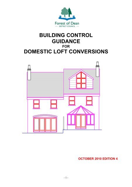
BUILDING CONTROL<br />
GUIDANCE<br />
FOR<br />
DOMESTIC LOFT CONVERSIONS<br />
- 1 -<br />
OCTOBER 2010 EDITION 4
Introduction<br />
This document intends to provide education and <strong>guidance</strong> on how some <strong>of</strong> the technical design<br />
and construction requirements <strong>of</strong> the Building Regulations 2010 can be achieved and met for<br />
<strong>l<strong>of</strong>t</strong> <strong>conversions</strong> to dwellings up to two storeys in height and within 4.5m <strong>of</strong> ground level and<br />
additional <strong>guidance</strong> is given for three storeys in height which has a floor 4.5m above ground<br />
level. For <strong>l<strong>of</strong>t</strong> <strong>conversions</strong> <strong>of</strong> four storeys or more with more than one floor above 4.5m please<br />
contact <strong>building</strong> <strong>control</strong> for advice.<br />
In all cases the design and construction <strong>of</strong> the proposed works is the responsibility <strong>of</strong> the<br />
designer, applicant and contractor and should be carried out to the relevant submitted and<br />
approved design. For further information reference should be made to the relevant Approved<br />
Document or standard as well as consulting a suitably qualified and experienced construction<br />
pr<strong>of</strong>essional.<br />
The Approved Documents listed below are available to purchase from The Stationary Office<br />
(TSO) on line at www.tsoshop.co.uk or telephone: 0870 600 5522.<br />
However, the Building Regulation requirements may be satisfied in other ways or non-standard<br />
ways by calculations or test details from a manufacturer or an approved 3rd party method <strong>of</strong><br />
certification such as BBA (British Board <strong>of</strong> Agreement) Certificate.<br />
This document can be made available on a range <strong>of</strong> other formats if required. For further<br />
information please contact us on 01594 810000.<br />
Approved Documents and sections they cover;<br />
A: Structure (2004 edition) including TRADA span tables for solid timber members in floors,<br />
ceilings and ro<strong>of</strong>s for dwellings (2nd edition 2008)*;<br />
B1: Fire safety in dwelling houses (2006 edition);<br />
C: Site preparation and resistance to contaminants & moisture (2004 edition);<br />
D: Toxic substances (1992 with 2002 amendments);<br />
E: Resistance to the passage <strong>of</strong> sound (2003 with 2004 amendments);<br />
F: Ventilation (2010 edition);<br />
G: Sanitation, hot water safety and water efficiency (2010 edition);<br />
H: Drainage and waste disposal (2002 edition);<br />
J: Combustion appliances & fuel storage systems (2010 edition);<br />
K: Protection from falling, collision and impact (1998 with 2002 amendments);<br />
L1B: Conservation <strong>of</strong> fuel and power in existing dwellings (2010 edition);<br />
N: Glazing – Safety in relation to impact, opening & cleaning (1998 with 2000 amendments);<br />
P: Electrical safety (2006 edition);<br />
Regulation 7 Materials and workmanship (1992 with 2000 amendments).<br />
Other <strong>guidance</strong> documents available: New Dwellings, New extensions<br />
Commercial/industrial <strong>building</strong>s & Fire Safety for Conversion <strong>of</strong> <strong>building</strong>s into Holiday Lets,<br />
Guest Houses & Supervised Groups with Learning Difficulties.<br />
Important note: Typical section details have been provided in these <strong>guidance</strong> notes for the<br />
more common construction methods used in dwellings. These details are suggested methods <strong>of</strong><br />
construction and are for <strong>guidance</strong> only. You are advised to contact a suitably qualified and<br />
experienced property pr<strong>of</strong>essional for details and specifications for the most suitable form and<br />
method <strong>of</strong> construction for your project.<br />
- 2 -
CONTENTS PAGE NUMBER<br />
INTRODUCTION 2<br />
1.0 CONVERTING AN EXISTING LOFT SPACE 6<br />
2.0 ENGAGING A PROPERTY PROFESSIONAL<br />
3.0 OBTAINING BUILDING REGULATIONS APPROVAL<br />
3.1 full plans application<br />
3.2 <strong>building</strong> notice application 7<br />
4.0 EXEMPT BUILDINGS AND WORK<br />
5.0 COMPETENT PERSON SCHEME<br />
6.0 PLANNING PERMISSION, LISTED BUILDING & CONSERVATION AREA CONSENTS 8<br />
7.0 THE PARTY WALL ACT 1996<br />
8.0 CONSTRUCTION (DESIGN AND MANAGEMENT) REGULATIONS 2007 (CDM)<br />
9.0 ASSESSING THE FEASIBILITY OF YOUR LOFT CONVERSION 9<br />
10.0 GENERAL TECHNICAL & PRACTICAL GUIDANCE FOR LOFT CONVERSIONS 10<br />
A1: PREPARATION, PROTECTION, ACCESS & DEMOLITION<br />
A2: INSPECTION OF THE EXISTING ROOF & STRUCTURE<br />
A3: ALTERATION, MODIFICATION & STRENGTHENING OF THE EXISTING ROOF/STRUCTURE<br />
Diagram 1: Typical plan layout <strong>of</strong> a <strong>l<strong>of</strong>t</strong> conversion with dormer pitched ro<strong>of</strong> 11<br />
Diagram 2: Typical section through a <strong>l<strong>of</strong>t</strong> conversion with dormer pitched ro<strong>of</strong> 12<br />
Diagram 3: Typical section through a <strong>l<strong>of</strong>t</strong> conversion with dormer flat ro<strong>of</strong><br />
A4: NEW PITCHED ROOFS 13<br />
Pitched ro<strong>of</strong> coverings<br />
Pitched ro<strong>of</strong> structure<br />
Ro<strong>of</strong> trusses (including attic & girder trusses)<br />
Cut ro<strong>of</strong> construction<br />
Table 1: Spans for Common Domestic Timber Rafter Sizes at 400mm spacing 14<br />
Table 2: Spans for Common Domestic Timber Ceiling Joist Sizes at 400mm spacing<br />
Table 3: Spans for Common Domestic Timber Purlin Sizes<br />
Table 4: Permissible Clear Spans for Common Ceiling Binders Sizes 15<br />
Diagram 4: Typical section through a pitched ro<strong>of</strong><br />
Ro<strong>of</strong> restraint<br />
Ro<strong>of</strong> insulation 16<br />
Table 5: Insulation laid horizontally between and over ceiling joists<br />
Table 6: Insulation fixed between/under rafters<br />
Table 7: Insulation fixed between/over rafters<br />
Diagram 5: Typical ro<strong>of</strong> valley detail 17<br />
Diagram 6: Typical section through a dormer ro<strong>of</strong><br />
Ro<strong>of</strong> ventilation 18<br />
A5: FLAT ROOF CONSTRUCTION<br />
Diagram 7: Typical section through a flat (cold) ro<strong>of</strong> 19<br />
Table 8: Spans for Common Flat Ro<strong>of</strong> Joist Sizes<br />
Table 9: Insulation Fixed Between/Under Flat Ro<strong>of</strong> Joists 20<br />
Table 10: Insulation Fixed above Flat Ro<strong>of</strong> Joists<br />
Valleys and lead work<br />
L<strong>of</strong>ts hatches, doors & Light wells to ro<strong>of</strong> spaces<br />
A6: NEW EXTERNAL WALLS 21<br />
Cavity walls<br />
Table11: Insulation requirements for external cavity walls<br />
External timber framed walls with render finish 22<br />
Diagram 8: Typical section through external timber framed walls with render finish<br />
External timber framed walls with cladding finish<br />
Diagram 9: Typical section through external timber framed walls with cladding finish 23<br />
Wall abutments<br />
Lintels & weep holes<br />
Structural columns/beams etc<br />
Expansion joints<br />
Strapping and restraint<br />
Cavity closers<br />
A7: INTERNAL LOAD BEARING WALLS 24<br />
Internal load bearing timber stud walls<br />
Diagram 10: Typical section through internal load bearing timber stud wall supporting<br />
ro<strong>of</strong> loads<br />
Table 12 : Insulation requirements to exposed timber framed walls<br />
Internal load bearing masonry partitions<br />
A8: INTERNAL NON LOAD BEARING PARTITIONS 25<br />
Internal masonry non-load bearing partitions<br />
Internal timber studwork non-load bearing partitions<br />
- 3 -
A9: UPGRADING EXISTING EXTERNAL WALLS 26<br />
Diagram 11: Typical plan layout <strong>of</strong> upgrading existing walls in <strong>l<strong>of</strong>t</strong> conversion<br />
Table 13: Insulation requirements for upgrading existing external walls<br />
A10: SEPARATING (PARTY) WALLS & FLOORS BETWEEN DWELLINGS 27<br />
Masonry party walls separating dwellings<br />
Timber frame party walls separating <strong>building</strong>s<br />
Upgrading sound insulation <strong>of</strong> existing separating walls<br />
Party floors separating <strong>building</strong>s<br />
Sound testing requirements<br />
A11: ADDITIONAL PROVISIONS FOR 3 STOREY BUILDINGS/EXTENSIONS 28<br />
Compressive strength <strong>of</strong> masonry units<br />
A12: INTERMEDIATE UPPER FLOOR(S)<br />
Diagram 12: Typical section through a <strong>l<strong>of</strong>t</strong> floor<br />
Diagram 13: Typical section through an upper floor 29<br />
Table 14: Spans for Common Domestic Floor Joist Sizes<br />
Table 15: Spans for Common Trimmer Joist supporting Trimmed Joists<br />
Table 16: Spans for Common Trimming Joist supporting Trimmer Joist<br />
Sound insulation to floors within the dwelling 30<br />
SVP pipe boxing<br />
Exposed intermediate upper floors<br />
Table 17: Insulation requirements to exposed intermediate floors<br />
PART B: FIRE SAFETY & MEANS OF ESCAPE 31<br />
MEANS OF ESCAPE FROM SINGLE STOREY DWELLING WITH NEW SECOND STOREY<br />
MEANS OF ESCAPE FROM TWO STOREY DWELLINGS WITH NEW THIRD STOREY 32<br />
Option 1: Protected stairway<br />
Option 2: Protected stairway with alternative exits at ground floor level 33<br />
Option 3: Fire separated 3 rd storey with alternative external/internal fire exit 34<br />
Option 4: Residential sprinkler systems for means <strong>of</strong> escape 35<br />
Fire doors<br />
Smoke alarms<br />
Fire resistance to new storey floor 36<br />
Permitted <strong>building</strong> openings in relation to a boundary:<br />
Openings within 1.0m <strong>of</strong> a boundary<br />
Openings more than 1.0m from a boundary<br />
Table 18: Permitted unprotected areas in relation to a relevant boundary<br />
Fire resistance to elements <strong>of</strong> structure etc<br />
Table 19: Fire resistance to common elements <strong>of</strong> structure etc<br />
Surface spread <strong>of</strong> flame: wall & ceiling linings 37<br />
Table 20: Surface spread <strong>of</strong> flame: Classification <strong>of</strong> wall & ceiling linings<br />
PART C: SITE PREPARATION AND RESISTANCE TO CONTAMINANTS & MOISTURE 38<br />
Horizontal damp pro<strong>of</strong> courses & trays (dpc’s)<br />
Vertical damp pro<strong>of</strong> courses & trays etc (dpc’s)<br />
PART D: CAVITY WALL FILLING WITH INSULATION BY SPECIALISTS<br />
PART E: RESISTANCE TO THE PASSAGE OF SOUND<br />
New Internal walls & floors in <strong>l<strong>of</strong>t</strong> conversion<br />
New/existing party walls and floors in <strong>l<strong>of</strong>t</strong> conversion<br />
PART F: VENTILATION 39<br />
Purge (natural) ventilation<br />
Mechanical extract ventilation & fresh air inlets for rooms without purge ventilation<br />
Background ventilation<br />
Mechanical extract ventilation rates<br />
General requirements for mechanical extract ventilation<br />
PART G: SANITATION, HOT WATER SAFETY AND WATER EFFICIENCY 40<br />
PART H: DRAINAGE AND WASTE DISPOSAL 41<br />
H1: FOUL WATER DRAINAGE<br />
Foul, rain & storm water drainage systems<br />
Waste pipes<br />
H2: SEPTIC TANKS, SEWAGE TREATMENT SYSTEMS & CESSPOOLS 42<br />
Existing septic tank & effluent drainage<br />
Non mains foul drainage waste water treatment systems<br />
Septic tanks<br />
Sewage treatment systems 43<br />
Treatment <strong>of</strong> sewage from septic tanks & sewage treatment systems<br />
Drainage fields<br />
Drainage mounds<br />
Wetlands/reed beds 44<br />
Percolation test method to calculate area <strong>of</strong> drainage field for septic tanks<br />
or sewage treatment systems.<br />
Diagram 14: Typical section through a septic tank/sewage treatment system drainage field 45<br />
Diagram 15 : Typical drainage field plan layout (not to scale)<br />
- 4 -
H3: RAINWATER DRAINAGE AND HARVESTING 46<br />
Rainwater gutters and down pipes<br />
Table 21: Gutter sizes & pipe outlet sizes for drainage <strong>of</strong> ro<strong>of</strong> areas<br />
Rainwater/ grey water harvesting storage tanks & systems<br />
Surface water drainage around the <strong>building</strong><br />
PART J: COMBUSTION APPLIANCES & FUEL STORAGE SYSTEMS 47<br />
SPACE & HOT WATER HEAT PRODUCING APPLIANCES IN GENERAL<br />
SOLID FUEL APPLIANCES UP TO 50KW RATED OUTPUT<br />
Construction <strong>of</strong> open fire place with recess & hearth<br />
Free standing stove with hearth<br />
Air supply (ventilation) to solid fuel appliances<br />
Table 22: Air supply (ventilation) to solid fuel appliances 48<br />
Carbon monoxide alarms<br />
Table 23: Sizes <strong>of</strong> flues in chimneys<br />
Construction <strong>of</strong> masonry chimneys 49<br />
Construction <strong>of</strong> factory made flue block chimneys<br />
Construction <strong>of</strong> factory made metal chimneys<br />
Configuration <strong>of</strong> flues serving open flue appliances<br />
Inspection & cleaning openings in flues<br />
Interaction <strong>of</strong> mechanical extract vents & opened flue solid fuel appliances<br />
Chimney heights 50<br />
Repair/relining <strong>of</strong> existing flues<br />
Notice plates for hearths & flues<br />
APPLIANCES OTHER THAN SOLID FUEL<br />
Interaction <strong>of</strong> mechanical extract vents & opened flue combustion appliances<br />
Gas appliances<br />
Oil appliances<br />
Gas heating appliances up to 70kw<br />
Oil heating appliances up to 45kW 51<br />
Renewable energy Installations<br />
PROVISION OF INFORMATION- COMMISSIONING CERTIFICATES (TESTING)<br />
FUEL STORAGE TANKS<br />
LPG tanks and cylinders up to 1.1 tonnes<br />
Oil tanks up to 3500 litres<br />
PART K: PROTECTION FROM FALLING, COLLISION AND IMPACT 52<br />
STAIRS, LANDINGS AND CHANGES IN LEVEL OF 600MM OR MORE (INCLUDING EXTERNAL STEPS)<br />
Diagram 16: Measuring rise & goings<br />
Diagram 17: Typical internal stair case & guarding construction details 53<br />
GUARDING TO EXTERNAL STEPPED ACCESS, BALCONIES, FLAT ROOFS<br />
& LOW LEVEL WINDOW OPENINGS<br />
PART L: CONSERVATION OF FUEL AND POWER IN EXISTING DWELLINGS 54<br />
LISTED BUILDINGS, CONSERVATION AREAS & ANCIENT MONUMENTS<br />
AREAS OF EXTERNAL WINDOWS, ROOF WINDOWS & DOORS<br />
NEW THERMAL ELEMENTS<br />
External glazing<br />
Table 24: U Values for new external windows & doors including ro<strong>of</strong> windows<br />
Closing around window & door openings<br />
Sealing Measures<br />
External Walls, ro<strong>of</strong>s, floors & swimming pool basin 55<br />
Table 25: U Values for new external walls, ro<strong>of</strong>s, floors & swimming pool basin<br />
RENOVATION/UPGRADING OF EXISTING THERMAL ELEMENTS<br />
Table 26: Renovation/upgrading <strong>of</strong> existing thermal elements<br />
Payback report<br />
ENERGY EFFICIENT LIGHTING 56<br />
Fixed internal lighting<br />
Fixed external lighting<br />
CONSEQUENTIAL IMPROVEMENTS<br />
COMMISSIONING OF FIXED BUILDING SERVICES<br />
PROVIDING INFORMATION -BUILDING LOG BOOK<br />
PART N: SAFETY GLAZING, OPENING & CLEANING 57<br />
Safety glass and glazing<br />
Diagram 18: Glazing in windows, partitions, doors, side panels/screens & walls<br />
PART P: ELECTRICAL SAFETY 58<br />
Electrical Installations<br />
EXTERNAL WORKS- PATHS, DRIVES, PATIO & GARDENS 59<br />
MATERIALS AND WORKMANSHIP 60<br />
ADDITIONAL BUILDING CONTROL SERVICES WE CAN PROVIDE<br />
GLOUCESTERSHIRE BUILDING CONTROL DEPARTMENTS CONTACT DETAILS 61<br />
USEFUL NUMBERS OF OTHER AGENCIES OR COMPANIES<br />
- 5 -
1.0 Converting an existing <strong>l<strong>of</strong>t</strong> space<br />
Converting an existing <strong>l<strong>of</strong>t</strong> space can be an easy and cost effective way <strong>of</strong> increasing living<br />
accommodation in most houses. This guide to <strong>l<strong>of</strong>t</strong> <strong>conversions</strong> will provide useful <strong>guidance</strong> on<br />
how some <strong>of</strong> the technical design and construction requirements <strong>of</strong> the Building Regulations<br />
can be achieved where the <strong>l<strong>of</strong>t</strong> space <strong>of</strong> an existing one or two storey dwelling is being<br />
converted into habitable accommodation to form an additional storey to the dwelling. Where the<br />
house has three or more storeys before the <strong>l<strong>of</strong>t</strong> is converted -please contact <strong>building</strong> <strong>control</strong> for<br />
further <strong>guidance</strong>.<br />
2.0 Engaging a property pr<strong>of</strong>essional<br />
This type <strong>of</strong> work can be complex and unless you are experienced in construction you will need<br />
to get some pr<strong>of</strong>essional advice from the following:<br />
1. Appointing a suitably qualified and experienced property pr<strong>of</strong>essional who will prepare<br />
drawings and designs for your proposal, obtain the necessary approvals and if required<br />
they will also help you to find a suitable builder and manage the project for you.<br />
2. Appointing a specialist company who can <strong>of</strong>fer a one stop shop for this type <strong>of</strong> work, they<br />
can prepare drawings and designs for your proposal, obtain the necessary approvals and<br />
carry out all the necessary construction works to complete the project.<br />
3. Using an experienced builder.<br />
3.0 Obtaining Building Regulations approval<br />
The <strong>building</strong> owner or agent must make a <strong>building</strong> regulations application & pay a fee for the<br />
proposed works. All work must comply with the 2010 Building Regulations and the technical<br />
design and constructional requirements <strong>of</strong> the current Approved Documents A to P and<br />
Regulation - 7 Materials and Workmanship.<br />
The person carrying out the <strong>building</strong> works is to liaise with and meet the requirements <strong>of</strong> the LA<br />
Building Control/Certifying Body, giving required notices <strong>of</strong> stages <strong>of</strong> works as required by the<br />
Building Regulations including:<br />
Foundation excavations before any concrete is laid<br />
Over site covering to ground floors before any concrete is laid<br />
Foul & surface water drainage before any pipes are covered over<br />
Structural timbers (upper storey floor joists/beams and ro<strong>of</strong> structure before any<br />
coverings are fixed<br />
Completion <strong>of</strong> <strong>building</strong>-prior to occupation<br />
There are two methods <strong>of</strong> making a Building Regulations application as follows:<br />
3.1 Full Plans application<br />
This is <strong>of</strong>ten thought <strong>of</strong> as the traditional way <strong>of</strong> applying for Building Regulations<br />
Approval. The <strong>building</strong> designer will draw up detailed plans and supporting information<br />
for the proposed scheme and will send them to us together with a completed application<br />
form and the necessary fee which are available to down load from our web site at:<br />
www.fdean.gov.uk. We will then check the details and following any necessary<br />
consultations and liaisons with the <strong>building</strong> designer a Building Regulations Approval will<br />
be issued.<br />
Work can start any time after the application has been received although it is wise to wait<br />
until the scheme has had its initial check under the Building Regulations, this usually<br />
takes between two and three weeks.<br />
- 6 -
Our team <strong>of</strong> surveyors will liaise with your builder and inspect the work as it progresses<br />
on site. When the project is satisfactorily completed a Building Regulations Completion<br />
Certificate will be issued showing that the project has been independently inspected and<br />
that it complied with the Building Regulations.<br />
3.2 Building Notice application<br />
This system is best suited to minor <strong>domestic</strong> work carried out by a competent builder.<br />
Under this scheme no formal Approval <strong>of</strong> plans is issued and work is approved on site as<br />
it progresses.<br />
To use the Building Notice process you or your agent will need to submit a completed<br />
Building Notice application form together with a site location plan and the required fee.<br />
The application forms are available to down load from our web site at:<br />
www.fdean.gov.uk. Work can commence 48 hours after the notice has been received.<br />
When work commences one <strong>of</strong> our surveyors will meet with your builder to discuss your<br />
intentions, to agree how the work should be carried out, agree when the work will need to<br />
be inspected and to establish whether any further information will be required.<br />
When the project is satisfactorily completed a Building Regulations Completion<br />
Certificate will be issued showing that the project has been independently inspected and<br />
that it complied with the Building Regulations.<br />
4.0 Exempt <strong>building</strong>s and work<br />
Green Houses & agricultural <strong>building</strong>s: Buildings used for agriculture or keeping <strong>of</strong> animals<br />
providing no part is used as as a dwelling and is more than 1.5 times its height from a <strong>building</strong><br />
containing sleeping accommodation<br />
Temporary <strong>building</strong>s: Buildings erected for less than 28 days<br />
Ancillary <strong>building</strong>s: Buildings used in connection with the sale <strong>of</strong> <strong>building</strong>s or plots on that site,<br />
or in connection with a <strong>building</strong> project or mine/quarry and contains no sleeping<br />
accommodation.<br />
Small detached <strong>building</strong>s (garages, workshops or sheds): A detached single storey <strong>building</strong><br />
with less than 30m 2 internal floor area, with no sleeping accommodation. If constructed<br />
substantially <strong>of</strong> combustible materials it must be positioned at least one metre from the<br />
boundary <strong>of</strong> its cartilage. Other detached <strong>building</strong>s with less than 15m 2 internal floor area, with<br />
no sleeping accommodation. (no boundary restrictions if constructed <strong>of</strong> combustible materials)<br />
Conservatory, porch, covered yard/way & carports: A detached single storey <strong>building</strong> with<br />
less than 30m 2 internal floor area, fitted with safety glass in critical locations in compliance with<br />
ADN. Existing walls, doors & windows <strong>of</strong> the <strong>building</strong> separating the conservatory or porch is to<br />
be retained or, if removed are replaced with elements that meet the energy efficiency<br />
requirements <strong>of</strong> ADL1B. The heating system <strong>of</strong> the dwelling must not be extended into the<br />
conservatory or porch. Carports must be open on two sides.<br />
5.0 Competent Person Scheme<br />
Certain works can be carried out by an installer who is registered with a Competent<br />
Persons Scheme and will not require <strong>building</strong> regulations approval. For a list <strong>of</strong> all<br />
scheme members go to www.competentperson.co.uk<br />
- 7 -
6.0 Planning Permission, listed <strong>building</strong> & conservation area consents<br />
Planning permission, listed <strong>building</strong>/conservation area consents may be required for your<br />
proposed development and no works should be commenced until approval has been<br />
given by the planning department.<br />
If the requirements <strong>of</strong> the <strong>building</strong> regulations will unacceptably alter the character or<br />
appearance <strong>of</strong> a historic/listed <strong>building</strong>/ancient monument or <strong>building</strong> within<br />
a conservation area, then the requirements may be exempt or improved to what is<br />
reasonably practical or acceptable and would not increase the risk <strong>of</strong> deterioration <strong>of</strong> the<br />
<strong>building</strong> fabric or fittings in consultation with the local planning authorities conservation<br />
<strong>of</strong>ficer. For any further information, please contact the FODDC duty planning <strong>of</strong>ficer on<br />
01594 810000.<br />
7.0 The Party Wall Act 1996<br />
If the project affects a party wall, you may be required to give your neighbor the<br />
required notice under the Party Wall Act.<br />
Two months notice in writing is to be given to adjoining owner(s) for the following works to an<br />
existing Party Wall:<br />
Support <strong>of</strong> beam<br />
Insert DPC through wall<br />
Raise wall or cut <strong>of</strong>f projections<br />
Demolition and re<strong>building</strong><br />
Underpinning<br />
Insert lead flashings<br />
Excavations within 3 meters <strong>of</strong> an existing structure where the new foundations will go<br />
deeper than adjoining foundations, or within 6 meters <strong>of</strong> an existing structure where the<br />
new foundations are within a 45 degree line <strong>of</strong> the adjoining foundations.<br />
In the event <strong>of</strong> a disagreement, a Party Wall Surveyor may be required to resolve the dispute<br />
under the terms <strong>of</strong> the Party Wall Act. Copies <strong>of</strong> the Party Wall Act can be obtained from the<br />
Council Offices or www.communities.gov.uk<br />
8.0 Construction (Design and Management) Regulations 2007 (CDM)<br />
The Construction (Design and Management) Regulations 2007 apply to every<br />
construction project. If you are about to undertake construction work, which could include<br />
alterations, extensions, routine maintenance, new build or demolitions, then you need to<br />
know to what extent these Regulations will apply to you and whether you are a duty<br />
holder under these Regulations.<br />
With non-<strong>domestic</strong>* projects expected to last longer than 30 days, or more than 500 man<br />
hours, you will require the assistance <strong>of</strong> an advisor called a CDM Co-ordinator, who<br />
should be appointed at the earliest opportunity, before detailed design work is complete.<br />
If you are a Client thinking <strong>of</strong> commissioning work, a Designer appointed to work on a<br />
project, or a builder/developer about to undertake work, you should be aware <strong>of</strong> your<br />
responsibilities or duties under CDM 2007.<br />
*Non-<strong>domestic</strong> Clients are people who commission <strong>building</strong> works related to a<br />
trade or business, whether for pr<strong>of</strong>it or not. This work can be carried out on a<br />
<strong>domestic</strong> property; it is the type <strong>of</strong> Client that matters, not the type <strong>of</strong> property.<br />
- 8 -
9.0 Assessing the feasibility <strong>of</strong> your <strong>l<strong>of</strong>t</strong> conversion<br />
Before commencing a <strong>l<strong>of</strong>t</strong> conversion it is important to assess the feasibility <strong>of</strong> the project. This<br />
will involve inspection <strong>of</strong> the existing <strong>l<strong>of</strong>t</strong> & dwelling to assess the following:<br />
Ro<strong>of</strong> structure & shape- The overall form, construction and pr<strong>of</strong>ile <strong>of</strong> the ro<strong>of</strong> will have a major<br />
bearing on the whether the ro<strong>of</strong> is suitable for conversion to a usable space. Traditional cut<br />
timber pitched ro<strong>of</strong>s with gable ends walls (cavity walls or solid walls at least 250mm thick) and<br />
horizontal ridges are generally easier to convert and can normally support structural beams than<br />
hipped ro<strong>of</strong>s or ro<strong>of</strong>s with intersecting pitches and valleys which may require more complicated<br />
structural designs.<br />
Trussed rafter ro<strong>of</strong>s constructed using a series <strong>of</strong> complex trusses should only be altered,<br />
modified and converted in compliance with details and calculations carried out by a suitable<br />
qualified and experience property pr<strong>of</strong>essional. No trussed rafter should ever be cut or modified<br />
in any way until a new supporting structure is in place which has been designed by a suitably<br />
qualified and experienced specialist designer. Further information for <strong>l<strong>of</strong>t</strong> <strong>conversions</strong> with<br />
trussed rafter ro<strong>of</strong>s can be obtained from TRADA at: www.tra.org.uk<br />
All existing timbers should be in a sound condition, any defective timber is to be replaced with<br />
new in compliance with details and calculations carried out by a suitable qualified and<br />
experience property pr<strong>of</strong>essional. Existing timbers are to be inspected and where necessary<br />
treated against insect and fungal attack by a suitable qualified and experience specialist.<br />
Ro<strong>of</strong> Coverings & ro<strong>of</strong>ing felt - Should be in a sound and weather tight condition; any<br />
defective coverings/felt should be replaced with matching new/existing sound coverings, fixed<br />
as manufacturer’s details.<br />
Ceilings- To the underside <strong>of</strong> the new storey floor should achieve 30 minutes fire resistance.<br />
Normally 13mm plaster board & skim or sound lath and plaster in older houses will achieve this,<br />
otherwise additional upgrading will be required.<br />
Internal space available – The ro<strong>of</strong> space should not have any chimneys or services passing<br />
centrally through the <strong>l<strong>of</strong>t</strong> space that cannot be easily moved, altered or modified by suitable<br />
experienced and qualified property pr<strong>of</strong>essionals. Structural alterations/modifications should be<br />
in compliance with details and calculations carried out by a suitable qualified and experience<br />
property pr<strong>of</strong>essional.<br />
Head room available- Is measured vertically from the top <strong>of</strong> the new floor (which typically can<br />
be 200mm above the existing ceiling joists) to the underside <strong>of</strong> the new horizontal/sloping<br />
ceilings (which can typically down stand 50 -75mm from the existing ro<strong>of</strong> structure). A minimum<br />
headroom <strong>of</strong> 2.0m is required at the head <strong>of</strong> the stairs to comply with <strong>building</strong> regulations. A<br />
ceiling height <strong>of</strong> 2.2 to 2.3 is preferred in the centre <strong>of</strong> the ro<strong>of</strong> in habitable rooms reducing to<br />
0.800 to 1.2m for the side walls on sloping ceilings so low furniture can be placed in front <strong>of</strong><br />
them. If your existing ro<strong>of</strong> pitch is less than 30 degrees and ro<strong>of</strong> span is less than 6 metres, a<br />
<strong>l<strong>of</strong>t</strong> conversion may be impractical and the only possibility may be to remove the ro<strong>of</strong> completely<br />
and replace it with attic trusses suitable for rooms in the ro<strong>of</strong> designed by a specialist.<br />
Means <strong>of</strong> escape- Three storey houses will require a protected stairs that connects to a hall<br />
and final exit at ground floor level or give access to at least two escape routes to final exits at<br />
ground level which will require separated by fire resisting construction and fire doors.<br />
Alternatively, the new top storey can be separated by fire resisting construction and provided<br />
with an alternative escape route (subject to planning permission), or a <strong>domestic</strong> sprinkler<br />
system can designed by a fire engineer. The full means <strong>of</strong> escape and fire safety requirements<br />
are covered in detail later in this <strong>guidance</strong>.<br />
- 9 -
10.0 General technical & practical <strong>guidance</strong> for <strong>l<strong>of</strong>t</strong> <strong>conversions</strong><br />
A1: Preparation, protection, access & demolition<br />
Provide all necessary scaffolding, access ladders, material hoists, temporary protection and<br />
working platforms etc for the <strong>l<strong>of</strong>t</strong> conversion which are to be erected, maintained, certificated,<br />
dismantled and removed by suitably qualified and insured specialists.<br />
All plumbing, drainage, heating, electrical services etc including re-siting <strong>of</strong> heating appliances/<br />
boilers/ flues /tanks etc to be altered /modified /adjusted as necessary by suitably qualified &<br />
experience specialists or registered competent persons, tested & appropriate certification<br />
issued where required in this specification.<br />
Any asbestos is to be inspected by a specialist, removed and disposed <strong>of</strong>f site by a specialistlicensed<br />
contractor in compliance with the Control <strong>of</strong> Asbestos Regulations 2006.<br />
Prior to and during works, the person carrying out the works is to liaise with and meet the<br />
requirements <strong>of</strong> the relevant Service Authorities, including the location and protection <strong>of</strong> all<br />
services as necessary.<br />
The builder is to allow for and maintain all temporary protection to the <strong>building</strong> to maintain<br />
weather tightness until completion <strong>of</strong> the works. All structural timber is to be grade C24, stress<br />
graded to BS 4978 and sawn to BS 4471. All timber is to be protected on site to minimize<br />
moisture content which must not exceed 22%.<br />
A2: Inspection <strong>of</strong> the existing ro<strong>of</strong> & structure<br />
Existing foundations, lintels and wall structure that will be built <strong>of</strong>f or support the new storey<br />
loads from the proposed works may need to be exposed at the discretion <strong>of</strong> the Building Control<br />
Surveyor and structural engineer to ensure that they are adequate and suitable - this may<br />
include opening up or excavating walls/floors (and making good to match the existing) to check<br />
internal foundations or walls. If they do not appear to be adequate to support the proposed<br />
works, details/justification <strong>of</strong> the proposed remedial works/alterations including necessary<br />
engineering calculations and details will need to be submitted for approval before works<br />
commence on site.<br />
A3: Alteration, modification & strengthening <strong>of</strong> the existing ro<strong>of</strong> & structure<br />
Over haul existing ro<strong>of</strong> coverings and structural timbers as necessary, replace defective and<br />
missing tiles, treated timber battens, ro<strong>of</strong>ing felt, lead valleys, flashings, facia boards, s<strong>of</strong>fit/<br />
barge boards and rainwater goods etc as necessary to match existing. Repoint/ rebuild<br />
defective masonry walls/ chimneys etc as necessary. Repair/ replace defective ro<strong>of</strong> timbers as<br />
necessary. Existing timbers to inspected, repaired, replaced and treated as necessary by a<br />
specialist with a warrant backed guarantee against insect & fungal attack.<br />
Alteration/modification/strengthening <strong>of</strong> the existing ro<strong>of</strong> structure/structural members/ walls etc<br />
should only be carried out/repaired/ replaced/ supported or removed in strict compliance with<br />
details and calculations received from a suitably qualified person. These details must be<br />
approved by <strong>building</strong> <strong>control</strong> before works commence on site.<br />
Trussed rafter ro<strong>of</strong>s constructed using a series <strong>of</strong> complex trusses should only be altered,<br />
modified and converted in compliance with details and calculations carried out by a suitable<br />
qualified and experience property pr<strong>of</strong>essional. No trussed rafter should ever be cut or modified<br />
in any way until a new supporting structure is in place which has been designed by a suitably<br />
qualified and experienced specialist designer. Further information for <strong>l<strong>of</strong>t</strong> <strong>conversions</strong> with<br />
trussed rafter ro<strong>of</strong>s can be obtained from TRADA at: www.tra.org.uk<br />
- 10 -
Diagram 1: Typical plan layout <strong>of</strong> a <strong>l<strong>of</strong>t</strong> conversion with dormer pitched ro<strong>of</strong> (not to scale)<br />
Existing walls with a<br />
threshold U value worse<br />
than 0.7, upgrade U value<br />
to 0.55 for cavity walls & 0.3<br />
for solid walls as follows:<br />
13mm vapour checked<br />
plaster board & skim<br />
75 x 50mm timber studs at<br />
400mm ctrs<br />
fixed to wall<br />
Thermal insulation fixed<br />
between studs as <strong>guidance</strong><br />
details<br />
Proposed dormer<br />
ro<strong>of</strong> omitted for<br />
clarity <strong>of</strong> layout<br />
Internal sound insulated stud<br />
partition as <strong>guidance</strong> details<br />
FD 20 fire<br />
door<br />
13mm vapour checked plaster board & skim<br />
12mm structural plywood skin & fixings to s/engineers details &<br />
calculations<br />
100mm timber studs at 400mm ctrs<br />
Thermal insulation fixed between studs as <strong>guidance</strong> details<br />
Load bearing studs supported by structural beams to<br />
s/engineers details & calculations<br />
- 11 -<br />
13mm vapour<br />
checked plaster<br />
board & skim<br />
75 x 50mm timber<br />
studs at 400mm ctrs<br />
fixed to wall<br />
Insulation fixed<br />
between studs as<br />
<strong>guidance</strong> details<br />
Smoke alarm<br />
30 minutes fire<br />
resisting (&<br />
sound<br />
insulating) stud<br />
partition to<br />
protect stairs as<br />
<strong>guidance</strong><br />
details<br />
Stairs & handrail<br />
as <strong>guidance</strong><br />
details<br />
Load bearing stud with thermal<br />
insulation as detailed below<br />
EXISTING SEPARATING<br />
WALL<br />
Upgrade sound<br />
insulation to separating<br />
walls between dwellings<br />
as necessary as<br />
<strong>guidance</strong> details<br />
ADJOINING<br />
UNHEATED ROOF<br />
SPACE
Diagram 2: Typical section through a <strong>l<strong>of</strong>t</strong> conversion with dormer pitched ro<strong>of</strong> (not to<br />
scale)<br />
Ro<strong>of</strong> insulation -see options<br />
in <strong>guidance</strong> notes<br />
13mm vapour checked<br />
plaster board with<br />
skim finish<br />
Ro<strong>of</strong> insulation & ventilation<br />
as detailed on other<br />
ro<strong>of</strong> pitch<br />
12mm plywood gusset screwed<br />
High level ro<strong>of</strong> vents equal to<br />
a continuous 5mm air gap with<br />
fly screen if not breathable<br />
type felt<br />
If existing rafter undersized fix<br />
additional rafters alongside<br />
existing -birds mouthed over<br />
& fixed to structural stud<br />
joist<br />
hanger<br />
Ceilings to achieve<br />
30 minutes fire<br />
resistance from under<br />
side<br />
Eaves ventilation required equal to a<br />
continuous 25mm air gap with fly screens<br />
both sides <strong>of</strong> ro<strong>of</strong> if not breathable type<br />
felt<br />
Structural stud partition as<br />
s/engineers details, insulated as<br />
detailed in <strong>guidance</strong> notes, with<br />
13mm<br />
v.c.plaster board and skim finish<br />
Structural beam to s/engineers<br />
details & calculations<br />
Existing ro<strong>of</strong> coverings<br />
Trimming joists &<br />
rafters to<br />
s/engineers details<br />
& calculations<br />
Ceiling joists- see <strong>guidance</strong><br />
notes for sizes<br />
Floor joist sizes - see <strong>guidance</strong><br />
notes for sizes suitable for spans<br />
and spacing for noggins<br />
Sound insulation - see <strong>guidance</strong> notes<br />
22mm thick moisture resistant t & g floor boards<br />
Note: see <strong>guidance</strong> notes for fire safety<br />
requirements, stairways /guarding<br />
details & checking exisitng foundations<br />
& lintels to support new storey loadings.<br />
Diagram 3: Typical section through a <strong>l<strong>of</strong>t</strong> conversion with dormer flat ro<strong>of</strong> (not to scale)<br />
Bitumen bedded stone chippings covering the whole ro<strong>of</strong> surface to a depth <strong>of</strong> 13mm<br />
To achieve a class AA designation in close proximity <strong>of</strong> boundary for spread <strong>of</strong> flame<br />
Treated flat ro<strong>of</strong> joists fixed to beam with heavy duty galvanized hangers,<br />
fixed to treated wall plates bolted to web <strong>of</strong> beam. Flat ro<strong>of</strong> joist sizes<br />
and spacing to suit clear spans as <strong>guidance</strong> notes<br />
Strip back & refix ro<strong>of</strong> coverings with new ro<strong>of</strong>ing felt & treated battens<br />
as necessary, dress flat ro<strong>of</strong> membrane over plywood & tiling fillet<br />
(150mm min above flat ro<strong>of</strong>) to provide water pro<strong>of</strong> junction. Provide<br />
temporary protection & support as <strong>guidance</strong> notes<br />
Suggested ridge detail- steel ridge beam supported on pad stones into<br />
load bearing walls/intermediate load bearing columns, with 50mm<br />
deep treated timber plate bolted to top <strong>of</strong> beam, rafters birds mouthed<br />
over plate and mechanically fixed.<br />
High level ro<strong>of</strong> vents equal to a continuous 5mm air gap with fly<br />
screen if not breathable type felt increase to 25mm to cross<br />
flat ro<strong>of</strong> (excludes warm ro<strong>of</strong>s)<br />
If existing rafter undersized fix additional rafters alongside<br />
existing -birds mouthed over & fixed to structural stud<br />
Ro<strong>of</strong> insulation -see options in <strong>guidance</strong> notes<br />
13mm vapour checked plaster board with<br />
skim finish<br />
joist<br />
hanger<br />
Ceilings to achieve<br />
30 minutes fire<br />
resistance from under<br />
side<br />
Eaves ventilation required equal to<br />
a continuous 25mm air gap with<br />
fly screens both sides <strong>of</strong> ro<strong>of</strong> if<br />
not breathable type felt<br />
Lay fiberglass insulation between<br />
joists and additional layer across joists<br />
(or other approved) as <strong>guidance</strong><br />
details. Ensure 50mm clear<br />
air space to underside <strong>of</strong> non<br />
breathable felts at eaves junction<br />
Lay 150mm fiberglass insulation<br />
between joist and additional<br />
170mm accross joists or other<br />
approved (U value 0.16). Ensure<br />
50mm clear air space to underside<br />
<strong>of</strong> non breathable felts at eaves<br />
junction<br />
Ceiling joists-see <strong>guidance</strong><br />
notes for sizes<br />
Structural stud partitions as<br />
s/engineers details, insulated as<br />
detailed in <strong>guidance</strong> notes, with<br />
13mm v.c.plaster board and<br />
skim finish<br />
Structural beams to s/engineers<br />
details & calculations<br />
Floor joist sizes - see <strong>guidance</strong><br />
notes for sizes suitable for spans<br />
and spacing for noggins<br />
Sound insulation - see <strong>guidance</strong> notes<br />
22mm thick moisture resistant t & g floor boards<br />
- 12 -<br />
Ro<strong>of</strong> insulation -see options<br />
in <strong>guidance</strong> notes<br />
Dormer ro<strong>of</strong> constructed as typical ro<strong>of</strong><br />
section detail and supported on timber<br />
wall construction with finishes to match<br />
existing or as stated in planning permission.<br />
See <strong>guidance</strong> noted for construction details.<br />
Trimming joists and rafters supporting dormer<br />
ro<strong>of</strong>s to s/engineers details and calculations.<br />
Double glazed window and means <strong>of</strong> escape<br />
openings as detailed in <strong>guidance</strong> notes<br />
Code 5 lead flashings<br />
High level ro<strong>of</strong> vents as main ro<strong>of</strong><br />
Eaves ventilation required<br />
equal to a continuous 25mm<br />
air gap with fly screens both<br />
sides <strong>of</strong> ro<strong>of</strong> if not breathable<br />
type felt<br />
Ro<strong>of</strong> insulation and eaves<br />
ventilation as detailed on other<br />
ro<strong>of</strong> pitch<br />
NOTE: Alterations to existing<br />
ro<strong>of</strong> structure including removal<br />
<strong>of</strong> structural members etc must<br />
be in compliance with structural<br />
engineers details & calculations<br />
which must be approved by<br />
<strong>building</strong> <strong>control</strong> before works<br />
commence on site.<br />
NEW FLAT ROOF<br />
Single ply polymeric or three ply built up felt ro<strong>of</strong>ing in bitumen water pro<strong>of</strong><br />
coverings applied by flat ro<strong>of</strong>ing specialist as spec.<br />
22mm external quality plywood decking or other approved<br />
Treated timber firing strips cut to 1:60 min gradient- laid with falls to gutter (allow<br />
50mm min air gap in depth <strong>of</strong> firing strip from u/side <strong>of</strong> deck to top <strong>of</strong> insulation<br />
50mm min air gap<br />
Note: see <strong>guidance</strong> notes for fire safety requirements, stairways /guarding<br />
details & checking exisitng foundations & lintels to support new storey loadings.<br />
Insulation fitted below ro<strong>of</strong> deck (cold ro<strong>of</strong> & will require cross ventilation as<br />
detailed) or insulation fixed above deck (warm ro<strong>of</strong> and will not require any<br />
ventilation). See <strong>guidance</strong> notes for flat ro<strong>of</strong> insulation options<br />
13mm plasterboard with foil backing or 500g polythene to provide a vapour check<br />
50mm welted drip on galvanized plate to centre line <strong>of</strong> gutter fixed to 75mm deep<br />
timber nosing piece<br />
Matching Upvc gutters, facia/barge board with 25mm continuous air gap<br />
with insect screen<br />
Timber lintel to s/engineers details & calculations<br />
Matching double glazed window fitted with means <strong>of</strong> esape<br />
openings in bedrooms (or inner rooms) see <strong>guidance</strong> noted for<br />
details<br />
Matching painted render on stainless steel lath with drained cavity<br />
or vertical tile cladding on insulated stud walls - see <strong>guidance</strong><br />
notes for details<br />
Code 5 lead flashings (and soakers to tile/ro<strong>of</strong> junction)<br />
Proprietary high level ro<strong>of</strong> vents equal to a continuos 5mm air gap<br />
fitted with insect screen<br />
NOTE: Alterations to existing ro<strong>of</strong> structure<br />
including removal <strong>of</strong> structural members<br />
etc must be in compliance with structural<br />
engineers details and calculations<br />
which must be approved by <strong>building</strong><br />
<strong>control</strong> before works commence on site.
A4: New pitched ro<strong>of</strong>s<br />
Pitched ro<strong>of</strong> coverings<br />
Ro<strong>of</strong> covering to consist <strong>of</strong> matching slate or tile and associated capping, verge/eaves details<br />
fixed in accordance with manufacturer’s details for pitch and exposure as detailed on the<br />
drawings. Cladding to be fixed to a minimum 25 x 50mm treated timber batten or to<br />
manufacturer’s directions and ro<strong>of</strong> timbers to be overlaid with un-tear able breathable/non<br />
breathable ro<strong>of</strong> felt underlay to BS 747 or relevant BBA certificate.<br />
Ro<strong>of</strong> to be formed from kiln-dried stress graded timbers sized, spacing, spans, bracing and<br />
fixings as detailed on the drawing or tables below. Alternatively, the ro<strong>of</strong> may be formed from<br />
proprietary prefabricated manufactured trusses/attic trusses and bracing to BS 5268 but both<br />
with a foil backed 12.5mm plasterboard and skim ceiling finish.<br />
Pitched ro<strong>of</strong> structure<br />
Ro<strong>of</strong> to be constructed using either manufactured ro<strong>of</strong> trusses or a cut ro<strong>of</strong> as follows:<br />
Ro<strong>of</strong> trusses (including attic & girder trusses)<br />
Ro<strong>of</strong> to be constructed using specialist designed and manufactured trusses (or Attic trusses<br />
where forming room in the ro<strong>of</strong>) @ 600ctrs (max) to BS 5268:3 1985 A2 94. Trusses to be fixed<br />
and braced strictly in accordance with manufacturers details and mechanically fixed to 100 x<br />
50mm sw treated wall plates via galvanized steel truss clips. Reinforced concrete pad stoned<br />
required to support girder trusses to details and calculations by a suitably qualified person.<br />
The person carry out the <strong>building</strong> work is to check and confirm the actual ro<strong>of</strong> pitch to the truss<br />
manufacturer prior to placing an order. Details <strong>of</strong> trusses to be prepared by specialist<br />
designer/manufacturer, submitted and approved by <strong>building</strong> <strong>control</strong> prior to commencing ro<strong>of</strong><br />
construction.<br />
Cut ro<strong>of</strong> construction<br />
Ro<strong>of</strong> to be constructed using kiln dried –stress graded timber. Rafters, ceiling joists, purlin,<br />
hanger and binder sizes as stated on tables below or see TRADA Span Tables- suitable for the<br />
proposed clear spans and all properly fixed together using approved fixings.<br />
Where the ceiling joists are raised above wall plate level they must be fixed within the bottom<br />
third <strong>of</strong> the rafter using 12mm diameter high tensile bolts and steel toothed connectors to<br />
connect each rafter and ceiling joist to prevent possible ro<strong>of</strong> spread. Joists raised above this<br />
level are to be designed by a suitably qualified person and approved by <strong>building</strong> <strong>control</strong> before<br />
works commence.<br />
Struts & braces to be 100 X 50mm, hips to be splayed rafter depth + 25mm (under 30 degree<br />
pitch the hips are to be designed by a suitably qualified person), lay-boards to be the splayed<br />
rafter depth + 25mm X 32mm thick, ridges to be splayed rafter depth + 25mm, all valleys beams<br />
are to be designed by a suitably qualified person, wall plates to be 100 x 50 fixed to inner skin <strong>of</strong><br />
cavity wall using galvanized strapping as detailed below.<br />
Hip rafters to have 100 X 75mm angle ties connected across wall plates in housed joints at<br />
corners <strong>of</strong> ro<strong>of</strong> & hip irons screwed to hip rafters.<br />
S<strong>of</strong>fits, fascias and barge boards etc to match the existing or in UPVC to BS 4576, fixed in<br />
compliance with manufacturers details.<br />
Allow for all necessary alteration/modification <strong>of</strong> any existing adjoining ro<strong>of</strong> as required to<br />
enable the proper completion <strong>of</strong> the works and in agreement with <strong>building</strong> <strong>control</strong>.<br />
- 13 -
Allow for <strong>building</strong> in as work proceeds or insertion <strong>of</strong> proprietary stepped/cavity tray dpc to<br />
follow line <strong>of</strong> new ro<strong>of</strong> 150mm above all ro<strong>of</strong>/wall abutments as necessary using code 5 lead<br />
flashings. Tie the new ro<strong>of</strong> into the existing, alter/modify/renew existing ro<strong>of</strong> coverings and form<br />
a weather tight structure.<br />
Fix 12.5mm foil backed plasterboard (joints staggered) and 5mm skim coat <strong>of</strong> finishing plaster to<br />
the underside <strong>of</strong> all ceilings using galvanized plasterboard nails.<br />
Ro<strong>of</strong> pitch to (single storey) single skin <strong>building</strong>s with walls 100mm thick should not exceed 40<br />
degrees without structural engineers details & calculations to confirm stability <strong>of</strong> the structure.<br />
Cut ro<strong>of</strong>s over 40° are to be braced to BS 5268.<br />
Table 1: Spans for Common Domestic Timber Rafter Sizes at 400mm spacing<br />
(Strength Class C24)<br />
Slope <strong>of</strong> Ro<strong>of</strong> (degrees)<br />
15-22 22-30 30-45<br />
Size <strong>of</strong> Rafter<br />
Maximum clear span (m)<br />
Breadth X Depth (mm)<br />
47 100<br />
47 125<br />
47 150<br />
47 170<br />
47 195<br />
2.52 2.58 2.66<br />
3.15 3.22 3.32<br />
3.76 3.85 3.97<br />
4.36 4.45 4.57<br />
4.87 4.98 5.14<br />
Table 2: Spans for Common Domestic Timber Ceiling Joist Sizes at 400mm spacing<br />
(Strength Class C24)<br />
Size <strong>of</strong> Ceiling Joist<br />
Maximum clear span (m)<br />
Breadth X Depth (mm)<br />
47 97<br />
1.93<br />
47 120<br />
2.56<br />
47 145<br />
3.37<br />
47 170<br />
4.00<br />
47 195<br />
4.73<br />
47 220<br />
5.47<br />
Table 3: Spans for Common Domestic Timber Purlin Sizes (Strength Class C24)<br />
Slope <strong>of</strong> Ro<strong>of</strong> (degrees)<br />
Size <strong>of</strong> Purlin<br />
Breadth X Depth<br />
(mm)<br />
75 125<br />
75 150<br />
75 175<br />
75 200<br />
75 225<br />
15-22 22-30 30-45<br />
Spacing <strong>of</strong> Purlins (mm)<br />
1500 1800 2100 1500 1800 2100 1500 1800 2100<br />
Maximum clear span (m)<br />
1.87 - - 1.91 - - 1.98 1.86 -<br />
2.24 2.10 1.99 2.29 2.15 2.04 2.37 2.23 2.11<br />
2.61 2.45 2.32 2.67 2.51 2.38 2.76 2.59 2.46<br />
2.98 2.80 2.65 3.05 2.87 2.71 3.16 2.96 2.81<br />
3.35 3.15 2.98 3.43 3.22 3.05 3.55 3.33 3.15<br />
- 14 -
Table 4: Permissible Clear Spans for Common Ceiling Binders Sizes<br />
(Strength Class C24)<br />
Size <strong>of</strong> Binder<br />
Breadth X Depth<br />
(mm)<br />
47 150<br />
47 175<br />
63 150<br />
63 175<br />
75 150<br />
75 175<br />
Spacing <strong>of</strong> Binders (mm)<br />
1200 1500 1800 2100 2400 2700<br />
Maximum clear span (m)<br />
2.19 2.06 1.96 1.87 1.80 -<br />
2.60 2.45 2.32 2.22 2.13 2.05<br />
2.45 2.31 2.20 2.10 2.02 1.95<br />
2.91 2.74 2.60 2.48 2.38 2.30<br />
2.62 2.47 2.35 2.25 2.16 2.08<br />
3.11 2.92 2.77 2.65 2.55 2.46<br />
Diagram 4: Typical section through a pitched ro<strong>of</strong> (not to scale)<br />
Ro<strong>of</strong> slates/tiles to match existing or as stated in planning permission<br />
fixed as manufacturers details and suitable for the pitch<br />
Breathable or non breathable ro<strong>of</strong>ing felt fixed as<br />
manufacturers details<br />
25 x 50mm treated battens at a guage to suit coverings<br />
Rafters (see construction details and table<br />
in specification for sizes <strong>of</strong> rafters suitable for<br />
clear spans)<br />
Ceiling joists (see construction details and table<br />
in specification for ceiling joist sizes suitable<br />
for clear spans<br />
Rain water gutter<br />
Facia/s<strong>of</strong>fit boards<br />
Eaves ventilation equal<br />
to a continuous 10mm<br />
air gap with insect screen<br />
(may not be required<br />
with certain breathable<br />
ro<strong>of</strong> membranes)<br />
Double glazed window bedrooms/<br />
inner rooms to be fitted with openings<br />
suitable for escape as detailed in<br />
the specification<br />
Wall plates<br />
(strapped at<br />
2.0m ctrs)<br />
Continuous<br />
insulation<br />
Sound insulated<br />
stud partition as<br />
detailed in<br />
specification<br />
Proprietary insulated steel lintels suitable for spans and<br />
loadings in compliance with lintel manufactures<br />
standard tables<br />
Ro<strong>of</strong> restraint<br />
Ro<strong>of</strong> and walls to be provided with lateral restraint straps across at least 3 timbers as noted in<br />
wall section at ceiling, wall plate and verge levels with 30 x 5mm x 1m galvanized metal straps<br />
or other approved to BSEN 845-1 at maximum 2m centers.<br />
- 15 -<br />
NOTE: Proprietary high level ro<strong>of</strong> vents to be installed<br />
where insulation follows slope <strong>of</strong> ro<strong>of</strong>- equal to a<br />
continuous 5mm air gap with insect screen<br />
Ridge tiles to match ro<strong>of</strong> coverings<br />
Ridge board (see specification for details)<br />
Hangers to support hangers if additional support is<br />
required to ceiling joists (contact <strong>building</strong> <strong>control</strong> for<br />
details)<br />
Binders to support ceiling joists if they require additional<br />
support (contact <strong>building</strong> <strong>control</strong> for details)<br />
Ro<strong>of</strong> insulation (see options in specification<br />
Galvanized steel strapping at 2m ctrs built into<br />
cavity and fixed over 3 rafters with noggins as<br />
detailed in specification<br />
Vapour checked plaster board
Ro<strong>of</strong> insulation<br />
Insulation to be fixed to manufactures details and must be continuous with the wall insulation<br />
but stopped back at eaves or at junctions with rafters to allow a 50mm air gap in ventilated cold<br />
ro<strong>of</strong>s.<br />
Table 5: Insulation laid horizontally between and over ceiling joists<br />
(Vented cold ro<strong>of</strong> achieving a U-value <strong>of</strong> 0.16 W/m².k)<br />
Product K -Value Position in ro<strong>of</strong><br />
Crown Wool & 0.036-0.037 150mm between joists &<br />
Rock-wool Roll<br />
Alternatives TBA<br />
150mm laid across joists<br />
Table 6: Insulation fixed between/under rafters<br />
(Vented cold ro<strong>of</strong> achieving a U-value <strong>of</strong> 0.18 W/m².k)<br />
Product K -Value Position in ro<strong>of</strong><br />
Kingspan Kooltherm K7 0.020 100mm friction fixed between<br />
rafters &<br />
Or other approved with a K<br />
value <strong>of</strong> 0.020<br />
Alternatives TBA<br />
0.021 42.5mm fixed under rafters*<br />
* Where rafters are only 100mm deep, battens should be provided to their underside to maintain<br />
a 50mm air gap above the insulation where a non breathable ro<strong>of</strong>ing felt is used or battened to<br />
allow a 25mm sag in felt if using a breathable ro<strong>of</strong>ing membrane as the manufacturers details.<br />
Table 7: Insulation fixed between/over rafters<br />
(Warm ro<strong>of</strong> achieving a U-value <strong>of</strong> 0.18 W/m².k)<br />
Product K -Value Position in ro<strong>of</strong><br />
Kingspan Kooltherm K7<br />
Or other approved with a K<br />
value <strong>of</strong> 0.020<br />
Alternatives TBA<br />
0.020 50mm fixed between rafters &<br />
55mm fixed over rafters<br />
25 x 50mm counter battens to be fixed over insulation to allow for sag in<br />
breathable ro<strong>of</strong>ing membrane as manufacturers details<br />
- 16 -
Diagram 5: Typical ro<strong>of</strong> valley detail (not to scale)<br />
125mm<br />
min<br />
Rafter birds<br />
mouthed over 150 x<br />
50mm wall plate<br />
(wall plated<br />
strapped at 2.0m<br />
ctrs<br />
Pcc pad stone or<br />
dense blockwork<br />
200mm<br />
min<br />
Diagram 6: Typical section through a dormer ro<strong>of</strong> (not to scale)<br />
Trimming<br />
joists as<br />
spec<br />
Rain water gutter, facia/s<strong>of</strong>fit<br />
boards etc as spec<br />
Eaves ventilation equal<br />
to a continuous 10mm<br />
air gap with insect screen<br />
(may not be required<br />
with certain breathable<br />
ro<strong>of</strong> membranes)<br />
13mm vapour checked plaster<br />
board & skim<br />
- 17 -<br />
Ro<strong>of</strong> coverings & ro<strong>of</strong> structure as<br />
specification<br />
& section details<br />
Breathable ro<strong>of</strong>ing membrane<br />
lapped over lead & forming drip<br />
Tiling fillet<br />
Code 5 lead lined gutter- lead sizes,<br />
drips & welted joints etc to the Lead<br />
Development association details<br />
25mm treated gutter board fixed to:<br />
50 x 50mm treated timber gutter<br />
bearer<br />
Ro<strong>of</strong> slates/tiles to match existing or as stated in<br />
planning permission fixed as manufacturers details and<br />
suitable for the pitch<br />
25 x 50mm treated battens at a guage to suit coverings<br />
Breathable or non breathable ro<strong>of</strong>ing felt fixed as<br />
manufacturers details<br />
Ridge board as specification<br />
Rafters (see construction details and<br />
table in specification for sizes <strong>of</strong> rafters<br />
suitable for clear spans)<br />
Ceiling joists (see construction details<br />
and table in specification for ceiling<br />
joist sizes suitable for clear spans<br />
Insulation deatils as tables in<br />
specification<br />
Dormer walls constructed with painted<br />
renders or cladding on insulated<br />
timber frame as spec details<br />
Code 5 lead flashing & valleys<br />
Dormer ro<strong>of</strong> supported on rafters<br />
doubled up & bolted together<br />
See main ro<strong>of</strong> for<br />
construction details
Ro<strong>of</strong> ventilation<br />
Ro<strong>of</strong> insulation to be continuous with the wall insulation but stopped back at eaves or at<br />
junctions with rafters to allow a 50mm air gap. Cross ventilation to be provided by a proprietary<br />
eaves ventilation strip equivalent to a 25mm continuous gap at eaves level with insect grill.<br />
Alternatively, where cross ventilation is not possible such as mono pitch, coved ceiling or room<br />
in the ro<strong>of</strong> provide additional ridge/high level ventilation equivalent to a 5mm gap in the form <strong>of</strong><br />
proprietary vent tiles spaced in accordance with manufacturer’s details.<br />
Ventilation to the ro<strong>of</strong> space may be omitted, only if a proprietary BBA or similar approved<br />
breathable ro<strong>of</strong> membrane, with minimum 25mm thick treated vertical counter battens and<br />
proprietary eaves carrier system is used. Breathable ro<strong>of</strong> membranes & proprietary ro<strong>of</strong> vents<br />
must always be installed as manufacturers details (note: some breathable membranes may also<br />
require additional ro<strong>of</strong> ventilation)<br />
A5: Flat ro<strong>of</strong> construction<br />
Flat ro<strong>of</strong> to be carried out as detailed on the drawings. Moisture content <strong>of</strong> timber should not<br />
exceed 20% and to be kiln dried & grade C24. Workmanship to comply to BS 8000:4. All fixings<br />
to be proprietary stainless steel or galvanized steel.<br />
Waterpro<strong>of</strong> coverings: to be either:<br />
3 layers <strong>of</strong> high performance felt (hot bonded together with bitumen) to a current BBA<br />
Certificate in compliance with BS8217<br />
Single layer system with a current BBA or WIMLAS Certificate<br />
Glass reinforced plastic (GRP) system with a current BBA or other approved<br />
accreditation<br />
Lead sheet fixed in compliance with the Lead Development Associations guide to good<br />
practice or in compliance with the Lead Sheet Associations technical <strong>guidance</strong> sheets<br />
available from: www.leadsheet.co.uk.<br />
Mastic asphalt fixed in compliance with the Mastic Asphalt Councils technical guides &<br />
specifications<br />
Waterpro<strong>of</strong> covering to be laid in compliance with manufacturers details by flat ro<strong>of</strong>ing specialist<br />
onto separating layer over ro<strong>of</strong> insulation layer in compliance with Table 14 below to form a<br />
‘warm ro<strong>of</strong>’ (or alternatively insulation fixed between/under joists in compliance with Table 13<br />
below forming a ‘cold ro<strong>of</strong>’) fixed to, 22mm external quality plywood decking or similar approved<br />
laid to 1:60/80 minimum gradient using firing strips at spacing to match joists, fixed onto timber<br />
flat ro<strong>of</strong> joists constructed <strong>of</strong> kiln dried structural grade timber with sizes and spacing suitable for<br />
the proposed clear span as annotated on the drawing or in compliance with Table 9 below.<br />
Surface finish to flat ro<strong>of</strong>s: to consist <strong>of</strong> bitumen bedded stone chippings covering the whole<br />
surface to a depth <strong>of</strong> 12.5mm to achieve a class AA, AB or AC fire rated designation for surface<br />
spread <strong>of</strong> flame.<br />
Restrain flat ro<strong>of</strong> to external walls by the provision <strong>of</strong> 30 x 5 x 1000mm lateral restraint straps at<br />
maximum 2000mm centers fixed to 100 x 50mm wall plates and internal wall faces<br />
Flat ro<strong>of</strong> insulation to be in compliance with tables 13 & 14 below. Flat ro<strong>of</strong> insulation is to be<br />
continuous with the wall insulation but stopped back to allow a continuous 50mm air gap above<br />
the insulation in ventilated cold decks. Cross ventilation to be provided on opposing sides by a<br />
proprietary eaves ventilation strip equivalent to a 25mm continuous gap at eaves level with<br />
insect grill. Note: Warm ro<strong>of</strong> applications ie insulation above the structural deck do not require<br />
ventilation.<br />
- 18 -
The design, workmanship & selection <strong>of</strong> materials should comply with Model Specification<br />
Sheet P.L.1 Built-Up Ro<strong>of</strong>ing: Plywood Deck, published by The British Flat Ro<strong>of</strong>ing Council.<br />
Metallic ro<strong>of</strong> trims to be <strong>of</strong> non-corrodible material & resistant to sunlight & not fixed through the<br />
water pro<strong>of</strong> covering. All timber to be treated using CCA vacuum/pressure or O/S double<br />
vacuum to BS 5268:5, including all cut ends <strong>of</strong> timber etc 300mm <strong>of</strong> any joint.<br />
All flat ro<strong>of</strong>ing works to be carried out by a specialist flat ro<strong>of</strong>ing contractor and all materials etc<br />
to be fitted in compliance with manufacturer’s details. Work should not be carried out during wet<br />
weather or when the deck has not fully dried out. A 500g vapour <strong>control</strong> barrier is required on<br />
the underside <strong>of</strong> the ro<strong>of</strong> below the insulation level. Fix 12.5mm foil backed plasterboard (joints<br />
staggered) and 5mm skim coat <strong>of</strong> finishing plaster to the underside <strong>of</strong> all ceilings using<br />
galvanized plasterboard nails.<br />
Diagram 7: Typical section through a flat (cold) ro<strong>of</strong> (not to scale)<br />
Welted drip<br />
25mm continuous air gap<br />
with insect screen<br />
wall plate & strapping as<br />
spec details<br />
Cavity wall as spec details<br />
1:60/80 gradient<br />
13mm diam stone chippings bedded in hot bitumen<br />
Flat ro<strong>of</strong> joist sizes and spacing as<br />
spec tables<br />
Water pro<strong>of</strong> coverings applied by flat ro<strong>of</strong>ing specialist as spec.<br />
Proprietary steel box beam as<br />
manf details suitable for clear span<br />
or timber lintel to s/engineers<br />
details & calculations to suit clear<br />
spans <strong>of</strong> openings<br />
Table 8: Spans for Common Flat Ro<strong>of</strong> Joist Sizes (Strength Class C24) Access for<br />
maintenance and repairs only<br />
Size <strong>of</strong> joist Spacing <strong>of</strong> joist (mm)<br />
Breadth X Depth 400 450 600<br />
(mm)<br />
Maximum clear span (m)<br />
47 97 2.02 1.99 1.90<br />
47 120 2.65 2.61 2.46<br />
47 145 3.36 3.27 2.97<br />
47 170 3.98 3.83 3.48<br />
47 195 4.55 4.38 3.98<br />
47 220 5.13 4.93 4.49<br />
75 220 5.94 5.73 5.23<br />
- 19 -<br />
External quality structural decking<br />
Note: if insulation is fixed above the structural deck (forming a<br />
warm ro<strong>of</strong>) the above ventilation details can be omitted<br />
Firing strips at 1:60 min gradient<br />
50mm min air gap<br />
Insulation to achieve a min U value <strong>of</strong><br />
0.2, fixed above or below structural<br />
decking as above tables<br />
Plasterboard with vapour check<br />
Welted drip<br />
Rain water gutters, facia/<br />
barge board<br />
25mm continuous air gap<br />
with insect screen
Table 9: Insulation Fixed Between/Under Flat Ro<strong>of</strong> Joists<br />
(Vented ‘cold ro<strong>of</strong>’ achieving a U-value <strong>of</strong> 0.18 W/m².k)<br />
Product K -Value Position in ro<strong>of</strong><br />
Kingspan K7<br />
Kingspan K18<br />
Or other approved with a<br />
K value <strong>of</strong> 0.020<br />
0.020<br />
0.021<br />
- 20 -<br />
140mm between joists (2 x 70mm)<br />
32.5mm fixed under joists<br />
Note: The joist depth must be sufficient to maintain a 50mm air gap above the<br />
insulation and cross ventilation to be provided on opposing sides by a<br />
proprietary ventilation strip equivalent to a 25mm continuous gap at eaves level<br />
with insect grill for ventilation <strong>of</strong> the ro<strong>of</strong> space.<br />
Table 10: Insulation Fixed above Flat Ro<strong>of</strong> Joists<br />
(Non vented ‘warm ro<strong>of</strong>’ achieving a U-value <strong>of</strong> 0.18 W/m².k)<br />
Product K -Value Insulation fixed above deck<br />
Kingspan Thermaro<strong>of</strong><br />
Or other approved with a K<br />
value <strong>of</strong> 0.020<br />
Alternatives TBA<br />
0.020 120mm fixed above deck in a single<br />
layer<br />
Valleys and lead work<br />
Lead work, flashing, soakers, valleys and gutters, etc, to be formed from Code 5 lead sheet and<br />
fully supported on treated valley boards, etc, and to have a minimum 150mm lap joints, dressed<br />
200mm under tiles, etc, and not to be fixed in lengths exceeding 1.5m and to be fixed in<br />
accordance with the ro<strong>of</strong> cladding manufacturers and the Lead Development Association<br />
recommendations.<br />
L<strong>of</strong>ts hatches, doors & Light wells to ro<strong>of</strong> spaces<br />
All hatches, doors and light wells in the ro<strong>of</strong> space to be insulated to the same standard as the<br />
ro<strong>of</strong>, draft stripped and positively fixed.
A6: New external walls<br />
Cavity walls (U-value 0.28 W/m².k - area weighted average value)<br />
Walls to consist <strong>of</strong> either approved reconstituted stone facings,100mm tooled flush jointed<br />
brickwork or 2 coat rendered 100mm dense concrete blockwork external skin dependant upon<br />
exposure with a 100mm thick lightweight high performance 2.8N/mm² insulation block with<br />
either a 13mm lightweight plaster finish or 12.5mm plasterboard skimmed dry lining. Where<br />
required external natural stone facings to be tied to external block work with wall ties as detailed<br />
below and foundation widths increased by 150mm.<br />
Walls to be built with 1:5/6 cement mortar and tied with BBA approved stainless steel wall ties<br />
suitable for cavity width at maximum spacing <strong>of</strong> 750mm horizontal (increased to 600mm if<br />
retaining partial fill insulation using proprietary retaining rings as manufacturers details), 450mm<br />
vertical and 225mm at reveals, verges and closings for cavities up to 100mm wide.<br />
Cavity width and insulation details to be constructed as Table below to achieve a U- value <strong>of</strong> not<br />
more than 0.28 W/m².k. Wall insulation to be continuous with ro<strong>of</strong> insulation level and taken<br />
below floor insulation levels as manufacturer’s details.<br />
Table11: Insulation requirements for external cavity walls with 100mm dense<br />
Brick or rendered block external skin & internal plaster/dry lining plaster finish<br />
Clear cavity<br />
Insulation type & Overall cavity Internal Block Type<br />
width required<br />
Partial cavity fill<br />
Minimum thickness width required & Thickness<br />
50mm 40 mm Kingspan 90mm 100 mm insulation<br />
Kooltherm K8 or<br />
block (k value 0.15 or<br />
Other approved with<br />
K value <strong>of</strong> 0.020<br />
lower)<br />
50mm 50 mm Kingspan 100mm 100 mm dense<br />
Kooltherm K8 or<br />
concrete block (K<br />
Alternatives TBA<br />
Full fill<br />
Other approved with<br />
K value <strong>of</strong> 0.020<br />
value 1.13)<br />
n/a 115mm full fill glass n/a 100 mm insulation<br />
fiber (K value 0.037)<br />
block (k value 0.15 or<br />
Alternatives TBA<br />
Suitable for full fill<br />
lower)<br />
- 21 -
External timber framed walls with render finish (U-value 0.28 W/m².k - area weighted<br />
average value)<br />
Render finish (to comply to BS 5262) - to match existing or as specified to be applied in 3<br />
coats at least 16mm – 20mm thick overall to render lath. First & second coats 1:3<br />
(cement : sand with plasticizer). final coat 1:6 (cement : sand with plasticizer)- proportions by<br />
volume. Render should be finished onto an approved durable render stop, angle beads or<br />
jointing sections- stainless steel or other approved using drilled or shot fired fixings only.<br />
Stainless steel render lath fixed (using stainless steel staples) to vertical studs at 600mm max<br />
ctrs. laps wired together at 150mm ctrs. (Mesh to be backed by a water resistant membrane) &<br />
fixed to: treated battens - 25 x 50mm preservative treated battens fixed vertically to studs at<br />
max 600mm ctrs using 75mm long hot dipped galv or stainless steel annular ring nails, fixed to:<br />
Breathable membrane- ‘Tyveck or similar approved suitable for timber framed walls to current<br />
BBA certification, fixed to: External quality plywood- 12mm thick marine ply wood (or other<br />
approved) fixed to: Treated timber frame constructed using: 100/150mm x 50mm head & sole<br />
plates and vertical studs at 400mm ctrs, to s/engineers details & calculations. Thermal insulation<br />
board in compliance with table below to be tightly friction fixed between studs with 13mm<br />
vapour checked plaster board fixed to internal face <strong>of</strong> studs and finished with 3mm skim coat <strong>of</strong><br />
finishing plaster. All junctions to have water tight construction & seal all perimeter joints with<br />
tape internally and with silicon sealant externally.<br />
Diagram 8: Typical section through external timber framed walls with painted render<br />
finish (not to scale)<br />
Masonry paint finish<br />
16-20mm thick render finish<br />
Stainless steel render lath with water<br />
resistant membrane to stop render<br />
filling cavity<br />
25 x 38mm treated timber battens<br />
at 600mm ctrs fixed vertically to form<br />
drained cavirty<br />
TYVEK or similar breathable membrane<br />
12mm external quality plywood or<br />
other approved<br />
Stainless steel stop bead forming drip<br />
Insect pro<strong>of</strong> mesh (non rust)<br />
100 x 50mm treated stud at 400mm<br />
ctrs<br />
Thermal insulation as <strong>guidance</strong><br />
details<br />
13mm vapour checked plaster<br />
board & skim finish<br />
100 x 50mm soleplates fixed to base<br />
Construction details as<br />
<strong>guidance</strong><br />
External timber framed walls with cladding finish (U-value 0.28W/m².k - area<br />
weighted average value)<br />
Approved timber/upvc weatherboarding/vertical wall tiling fixed with proprietary rust resistant<br />
fixings to: 50 X 25mm treated battens/counter battens at 400mm ctrs fixed to: Tyvek vapour<br />
permeable membrane suitable for timber framed walls & fixed as manufacturers details to:<br />
12mm WPB ext quality plywood sheathing (joints covered by dpc/battens) fixed to 100 X 50mm<br />
timber studs at 400mm ctrs with 100 X 50mm timber head & sole plates & 2 rows noggins and<br />
diagonal bracing as S/Engineers details. Studs exceeding 2.5m high to be designed by<br />
Structural Engineer. Thermal insulation board in compliance with table below to be tightly<br />
friction fixed between studs with 13mm vapour checked plaster board fixed to internal face <strong>of</strong><br />
studs and finished with 3mm skim coat <strong>of</strong> finishing plaster. All junctions to have water tight<br />
construction & seal all perimeter joints with tape internally and with silicon sealant externally.<br />
- 22 -
Diagram 9: Typical section through external timber framed walls with cladding finish<br />
(not to scale)<br />
Upvc weatherboarding/vertical wall tiling<br />
fixed with proprietary rust resistant fixings<br />
25 x 38mm treated timber battens<br />
at 600mm ctrs fixed vertically to form<br />
drained cavirty<br />
TYVEK or similar breathable membrane<br />
12mm external quality plywood or<br />
other approved<br />
Cladding stop fillet & insect pro<strong>of</strong> mesh<br />
Wall abutments<br />
Vertical junctions <strong>of</strong> new and old walls to be secured with proprietary pr<strong>of</strong>iled stainless steel<br />
metal crocodile type system with a continuous cavity fixed with DPC and pointed with flexible<br />
mastic as manufacturer’s details.<br />
Lintels & weep holes<br />
Proprietary manufactured lintels to current British Standards/Euro codes (including specialist<br />
lintels supporting stone facings) are to be provided over all structural openings. The positions,<br />
types, sizes, end bearings etc <strong>of</strong> lintels must be in compliance with the lintel manufacturers<br />
standard tables suitable for the proposed loadings and clear spans. Stop end and dpc trays to<br />
be provided above all externally located lintels in compliance with lintel manufacturer’s details.<br />
Weep holes at 450mm centers with at least two per opening.<br />
Structural columns/beams etc<br />
Non proprietary beams/columns including pad stone to be fabricated and installed in<br />
compliance with details and structural calculations carried out by a suitably qualified and<br />
experienced person, which must be approved by <strong>building</strong> <strong>control</strong> before works commence on<br />
site. Dpc trays to be provided above all externally located beams. Weep holes at 450mm<br />
centers with at least two per opening.<br />
Expansion joints<br />
External walls should be provided with adequately spaced and sized expansion joints, in<br />
accordance with masonry manufactures details with adequate tying to each side <strong>of</strong> the joint and<br />
leaf <strong>of</strong> masonry using stainless steel wall ties (normally at each block height) and sealed<br />
externally with a proprietary flexible mastic sealant. (Normally expansion joints are 10-12mm<br />
wide and spaced vertically at max 12m ctrs in brick work & 6m ctrs in block work)<br />
Strapping and restraint<br />
Walls to be restrained at intermediate floor, ceiling and gable walls by the provision <strong>of</strong> 30 x 5 x<br />
1000mm lateral restraint straps or other approved in compliance with BS EN 845-1, at maximum<br />
2m centers carried across at least 3 joists or rafters, etc, with a minimum <strong>of</strong> 38mm wide x ¾<br />
depth noggins.<br />
Cavity Closers<br />
Proprietary acoustic/insulated fire stop cavity closers, or similar are to be provided to all cavity<br />
openings/closings, tops <strong>of</strong> walls and junctions with other properties.<br />
- 23 -<br />
100 x 50mm treated stud at 400mm<br />
ctrs<br />
Thermal insulation as <strong>guidance</strong><br />
details<br />
13mm vapour checked plaster<br />
board & skim finish<br />
100 x 50mm soleplates fixed to base<br />
Construction details as<br />
<strong>guidance</strong>
A7: Internal load bearing walls<br />
Internal load bearing timber stud walls<br />
Load bearing timber stud walls to be in compliance with details and calculations by a suitably<br />
qualified and experienced person, which must be approved by <strong>building</strong> <strong>control</strong> before works<br />
commence on site.<br />
Typically load bearing stud walls not exceeding 2.5m high are to be constructed <strong>of</strong> 100 x 50mm<br />
C24 s<strong>of</strong>t wood studs fixed vertically at 400mm ctrs with head and sole plates and intermediate<br />
noggins fixed at 600mm, with thermal insulation friction fixed air tight between studs as detailed<br />
in table below, with 12mm thick structural plywood glued & screwed to the full height & width <strong>of</strong><br />
the room side face <strong>of</strong> the stud wall and finished with 15 mm plasterboard and skim. Insulated &<br />
draught pro<strong>of</strong>ed access hatches to be formed between studs. New rafters to be birds mouthed<br />
over and mechanically fixed to head plate, and mechanically fixed to existing rafters by an<br />
approved method.<br />
Diagram 10: Typical section through internal load bearing timber stud wall supporting<br />
ro<strong>of</strong> loads (not to scale)<br />
Table 12 : Insulation requirements to exposed timber framed walls (U-value 0.28 W/m².k)<br />
Insulation Type Minimum Thickness mm<br />
Kingspan Kooltherm K12 or other<br />
90 mm<br />
approved with a K value <strong>of</strong> 0.020<br />
Alternatives TBA<br />
Internal load bearing masonry partitions<br />
Internal load bearing walls to be minimum100mm thick 7N/mm2 dense concrete blocks (actual<br />
wall thickness must not be less than the wall it supports above), built <strong>of</strong>f suitable foundations<br />
with pre-cast concrete/proprietary steel lintels over openings (in compliance with lintel<br />
manufacturers span tables) and walls bonded/tied to external or party walls with proprietary ties<br />
each course and restrained by floor or ceiling joists/trusses.<br />
- 24 -<br />
New rafter fixed alongside existing, birds mouthed<br />
over & mechanically fixed over new stud<br />
100 x 50mm timber head plate<br />
100 x 50 vertical timber studs at 400mm ctrs<br />
Thermal insulation friction fixed tightly between studs<br />
12mm structural plywood glued & screwed to studs<br />
15mm vapour checked plaster board & skim<br />
100 x 50 timber sole plate<br />
New structural beam supporting load bearing stud<br />
to s/engineers details & calculations
A8: Internal non load bearing partitions<br />
Internal masonry non-load bearing partitions<br />
Internal non-load bearing partitions to be constructed <strong>of</strong> 100mm 2.8/mm² dense concrete blocks<br />
built <strong>of</strong>f a thickened floor slab and tied/block bonded to all internal and external walls at<br />
maximum 225mm centers with either a plaster or dry lined finish as the external walls.<br />
Internal timber studwork non-load bearing partitions<br />
Non-load bearing stud partitions are to be constructed <strong>of</strong> 100 x 50mm s<strong>of</strong>t wood studs, fixed<br />
vertically at 400mm ctrs with head and sole plates and intermediate noggins fixed at 600mm<br />
with a minimum <strong>of</strong> 25 mm <strong>of</strong> 10Kg/m² proprietary sound insulation quilt suspended in the stud<br />
and finished with 15 mm plasterboard and skim both sides.<br />
- 25 -
A9: Upgrading existing external walls<br />
Where existing external walls are to be used as part <strong>of</strong> the <strong>l<strong>of</strong>t</strong> conversion and have a threshold<br />
U-value worse than 0.7, the U-values should be upgraded to 0.55 for cavity walls & 0.3 for solid<br />
walls. Upgrade walls typically using 75 x 50mm s<strong>of</strong>t wood studs at 400mm ctrs fixed vertically to<br />
existing walls with mechanical fixings (with a strip <strong>of</strong> damp pro<strong>of</strong> course between stud & wall if<br />
there is a risk <strong>of</strong> moisture penetration), thermal insulation to be friction fixed air tight between<br />
studs as detailed in table below and 15 mm vapour checked plasterboard fixed to studs with<br />
plaster skim finish. Existing solid external walls less than 328mm thick in rendered stone or<br />
brick or less than 250mm thick in rendered blockwork, should be tanked internally with a BBA or<br />
other approved tanking system to prevent the ingress <strong>of</strong> moisture into the <strong>building</strong>.<br />
Diagram 11: Typical plan layout <strong>of</strong> upgrading existing walls in <strong>l<strong>of</strong>t</strong> conversion (not to<br />
scale)<br />
Table 13: Insulation requirements for upgrading existing external walls<br />
External wall type Insulation Type Minimum<br />
Cavity walls with threshold Uvalue<br />
worse than 0.7, upgrade U-<br />
value to 0.55<br />
Solid walls with threshold U-value<br />
worse than 0.7, upgrade U-value<br />
to 0.30<br />
Existing walls with a<br />
threshold U value worse<br />
than 0.7, upgrade U value<br />
to 0.55 for cavity walls & 0.3<br />
for solid walls as follows:<br />
13mm vapour checked<br />
plaster board & skim<br />
75 x 50mm timber studs at<br />
400mm ctrs fixed to dpc<br />
strip & existing wall<br />
Thermal insulation fixed<br />
between studs as <strong>guidance</strong><br />
details<br />
Solid external walls less than<br />
328mm thick rendered<br />
stone/brick or less than<br />
250mm thick rendered<br />
blockwork to be tanked<br />
internally with a BBA<br />
approved water pro<strong>of</strong><br />
tanking system to prevent<br />
ingress <strong>of</strong> moisture into the<br />
<strong>building</strong><br />
Kingspan Kooltherm K12 or other<br />
approved with a K value <strong>of</strong> 0.020<br />
Kingspan Kooltherm K12 or other<br />
approved with a K value <strong>of</strong> 0.020<br />
- 26 -<br />
Thickness mm<br />
60 mm<br />
70mm
A10: Separating (party) walls & floors between dwellings<br />
( Also see relevant sections in ADE)<br />
Masonry party walls separating dwellings (U-value 0.2 W/m 2 .K)<br />
Party walls to be constructed <strong>of</strong> 2 skins <strong>of</strong> plastered 100mm dense concrete block with a clear<br />
50mm cavity and BBA approved wall ties spaced as external walls up to the underside <strong>of</strong> the<br />
ro<strong>of</strong> and fire stopped with mineral wool or an approved proprietary intumescent product to<br />
achieve a minimum 45dB value for airborne sound insulation. The party wall is to be<br />
bonded/tied to the inner leaf and the junction <strong>of</strong> cavities are to be fire stopped throughout its<br />
length with a proprietary acoustic/ insulated fire stop cavity closer and all other vertical and<br />
horizontal cavities are to be closed in a similar manner to provide effective edge sealing and a<br />
U-value <strong>of</strong> 0.2 W/m 2 .K.<br />
Timber frame party walls separating <strong>building</strong>s (U-value 0.2 W/m 2 .K)<br />
Timber framed stud walls to achieve a minimum 45 dB value for airborne sound insulation and<br />
constructed with 100 x 50mm sawn timber studs at 400mm ctrs with head & sole plates, with 2x<br />
50mm thick layers ROCKWOOL RWA 45 mineral wool friction fixed between studs, and 2x<br />
15mm thick layers <strong>of</strong> ‘LAFARGE dB check’ wall board fixed both sides <strong>of</strong> stud (joints staggered)<br />
with skim coat <strong>of</strong> plaster finish- as wall board manufacturers details. No electrical fittings to be<br />
fixed into/onto party walls & all gaps to be fire sealed & smoke stopped to the full height and<br />
width <strong>of</strong> the party wall and upto the underside <strong>of</strong> the ro<strong>of</strong> coverings using mineral wool (not<br />
glass wool) or an approved proprietary intumescent product to provide effective edge sealing<br />
and a U-value <strong>of</strong> 0.2 W/m 2 .K.<br />
Upgrading sound insulation <strong>of</strong> existing separating walls<br />
Existing wall should be at least 100mm thick, <strong>of</strong> masonry construction and plastered on<br />
both faces. With other types <strong>of</strong> existing wall the independent panels should be built on<br />
both sides.<br />
Construct new independent frame fixed at least 10mm from one side <strong>of</strong> the existing wall<br />
using either; 100 x 50mm timber studs at 400mm ctrs fixed onto head & sole plates or to<br />
a proprietary galvanised metal frame, fixed as manufacturers details. Fix 50mm thick<br />
ROCKWOOL RWA 45 sound insulation or other approved (min density 16kg/m3) friction fixed<br />
between studs<br />
Fix two layers <strong>of</strong> 15mm thick dB checked wall board with staggered joint and plaster skim<br />
finish to the independent frame using mechanical fixings. Note- allow a minimum<br />
distance <strong>of</strong> 35mm between face <strong>of</strong> existing wall & inner wall board face.<br />
No electrical fittings to be fixed into/onto party walls & all gaps to be fire sealed & smoke<br />
stopped to the full height and width <strong>of</strong> the party wall and upto the underside <strong>of</strong> the ro<strong>of</strong><br />
coverings using mineral wool (not glass wool) or an approved proprietary intumescent<br />
product to provide effective edge sealing and a U-value <strong>of</strong> 0.2 W/m 2 .K.<br />
Party floors separating <strong>building</strong>s<br />
Outside the scope <strong>of</strong> this <strong>guidance</strong>- see relevant sections in ADE<br />
Sound testing requirements<br />
Pre completion sound testing is required for all new/upgraded party walls/floors which<br />
must be carried out by a suitably qualified person or specialist to demonstrate<br />
compliance with Approved Document E and copy <strong>of</strong> test results sent to <strong>building</strong> <strong>control</strong>.<br />
- 27 -
A11: Additional provisions for 3 storey <strong>building</strong>s/extensions<br />
Compressive strength <strong>of</strong> masonry units<br />
The compressive strength <strong>of</strong> bricks and blocks used in three storey construction is as follows:<br />
(i) Outer leaf <strong>of</strong> cavity wall – Blocks & bricks to be 7N/mm2 from foundation level upto the<br />
underside <strong>of</strong> the structural ro<strong>of</strong>.<br />
(ii) Inner leaf <strong>of</strong> cavity wall – Blocks to be 7N/mm2 from foundation level upto the underside <strong>of</strong><br />
the first floor level. Blocks above this level upto the underside <strong>of</strong> the structural ro<strong>of</strong> to be<br />
2.8N/mm2.<br />
(iii) Internal walls – Blocks to be 7N/mm2 and 140mm thick upto the underside <strong>of</strong> the first floor<br />
level. Blocks above this level upto the underside <strong>of</strong> the structural ro<strong>of</strong> to be 2.8N/mm2.<br />
A12: Intermediate upper floor(s)<br />
Floor to be constructed <strong>of</strong> kiln dried structural grade timber joists with sizes and spacing suitable<br />
for the proposed clear span as annotated on the drawing or in compliance with the tables below.<br />
Joists to be supported by heavy-duty proprietary galvanized metal restraint joist hangers built<br />
into walls or fixed to treated timber wall plates (same sizes as joists) resin bolted to walls at<br />
600mm centers using approved 16mm diameter stainless steel fixings. Alternatively, joists can<br />
be built into walls using approved proprietary sealed joist caps. Joists are to be doubled up and<br />
bolted together for trimmers, under partitions and baths.<br />
Floor void between joists to be insulated with a minimum thickness <strong>of</strong> 100 mm <strong>of</strong> 10Kg/m³<br />
proprietary sound insulation quilt, ceiling to be a minimum 15mm plasterboard and skim and<br />
floor joist covering to be a minimum <strong>of</strong> 20mm s<strong>of</strong>twood tongue and groove s<strong>of</strong>twood boards or<br />
moisture resistant particle/chipboard to give overall 30 minutes fire resistance. Floor joists to be<br />
provided with 1 row <strong>of</strong> 38 x ¾ depth solid strutting at ends between joist hangers or proprietary<br />
galvanized struts to BS EN 10327 fixed as manufacturers details, at mid span for 2.5 – 4.5m<br />
spans and 2 rows at ¹/3 points for spans over 4.5m.<br />
Diagram 12: Typical section through a <strong>l<strong>of</strong>t</strong> floor (not to scale)<br />
Steel beam to s/engineers<br />
details & calculations with<br />
100 x 50mm timber plate<br />
bolted to top flange.<br />
(beam fixed above existing<br />
ceiling joists on pad stones)<br />
- 28 -<br />
22mm thick moisture resistant t & g floor boards fixed to joists<br />
Floor joists fixed between existing joists. Joists sizes,<br />
spacing & noggins suitable for clear spans as <strong>guidance</strong><br />
notes & tables<br />
100mm thick sound insulation as <strong>guidance</strong> notes<br />
Ceilings to achieve 30 minutes fire resistance from<br />
under side<br />
Heavy duty galvanised hangers supporting floor<br />
joists. Hangers fixed to timber plate bolted into<br />
web <strong>of</strong> beam using 12mm high tensile bolts at<br />
800mm ctrs
Diagram 13: Typical section through an upper floor (not to scale)<br />
Double glazed window bedrooms/<br />
inner rooms to be fitted with openings<br />
suitable for escape as detailed in<br />
the specification<br />
100mm minimum width insulation block (see<br />
options in specification)<br />
Wall grade insulation (see options in<br />
specification)<br />
50mm clear cavity if using partial fill cavity<br />
wall insulation (see options in specification)<br />
Wall ties and spacings as detailed in<br />
specification<br />
100mm minimum width external wall in<br />
materials to match existing or as specified in<br />
planning permission<br />
Proprietary insulated steel lintels (with dpc<br />
trays and stop ends) suitable for clear spans<br />
and loadings in compliance with lintel<br />
manufactures standard tables<br />
Table 14: Spans for Common Domestic Floor Joist Sizes (Strength Class C24)<br />
Size <strong>of</strong> joist<br />
Breadth X Depth<br />
(mm) (mm)<br />
47 97<br />
47 120<br />
47 145<br />
47 170<br />
47 195<br />
47 220<br />
75 220<br />
Spacing <strong>of</strong> joist (mm)<br />
400 450 600<br />
Maximum clear span (m)<br />
2.12 2.01 1.75<br />
2.70 2.59 2.34<br />
3.25 3.13 2.84<br />
3.81 3.66 3.32<br />
4.36 4.19 3.81<br />
4.84 4.70 4.29<br />
5.41 5.26 4.91<br />
Table 15: Spans for Common Trimmer Joist supporting Trimmed Joists<br />
(Strength Class C24)<br />
Length <strong>of</strong> trimmed joists (m)<br />
1.0 2.0 3.0 4.0<br />
Size <strong>of</strong> trimmer (mm) Clear span <strong>of</strong> trimmer joist (m) supporting<br />
2 x 47 x 145<br />
2 x 47 x 170<br />
2 x 47 x 195<br />
2 x 47 x 220<br />
2 x 75 x 220<br />
trimmed joists<br />
2.68 2.27 1.97 1.68<br />
3.21 2.68 2.33 1.99<br />
3.69 3.09 2.69 2.31<br />
4.17 3.50 3.06 2.62<br />
4.81 4.13 3.62 3.21<br />
Table 16: Spans for Common Trimming Joist supporting Trimmer Joist<br />
(Strength Class C24)<br />
Length <strong>of</strong> trimmer joist (m)<br />
1.0 2.0 3.0 max<br />
Size <strong>of</strong> trimming joist Clear span <strong>of</strong> trimming joist (m) supporting<br />
(mm)<br />
2 x 47 x 145<br />
2 x 47 x 170<br />
2 x 47 x 195<br />
2 x 47 x 220<br />
2 x 75 x 220<br />
trimmer joist<br />
Damp pro<strong>of</strong> course<br />
and insulated closer<br />
Galvanized steel<br />
straps at 2m ctrs built<br />
into cavity and fixed<br />
over 3 joists with<br />
noggins<br />
Floor joists doubled<br />
up under partition<br />
walls & baths<br />
Sound insulated plaster<br />
board achieving 30<br />
minutes fire resistance<br />
2.62 2.42 2.25<br />
3.08 2.84 2.65<br />
3.54 3.27 3.05<br />
3.99 3.70 3.46<br />
4.66 4.32 4.05<br />
- 29 -<br />
Sound insulated stud partition<br />
22mm t & g moisture resistant floor boarding<br />
Strutting between joist (see<br />
specification for spacings)<br />
Floor joists (see construction<br />
details and table in<br />
specification for sizes <strong>of</strong> joists<br />
suitable for clear spans)<br />
Sound insulation quilt<br />
as specification<br />
100mm dense<br />
concrete partitions<br />
precast<br />
concrete/proprieteray<br />
steel lintols, sizes<br />
suitable for clear spans<br />
as manufactures<br />
standard tables
Sound insulation to floors within the dwelling<br />
Intermediate floors to be provided with sound insulation as described in the relevant floor<br />
section in this document.<br />
SVP pipe boxing<br />
SVP pipe boxing to consist <strong>of</strong> s<strong>of</strong>t wood framing, 2 layers <strong>of</strong> 15mm plasterboard and skim and<br />
mineral wall sound insulation quilt. Boxing to be continuously carried up to ro<strong>of</strong> space for soil<br />
and vent pipe and provided with air grills where an air admittance valve is used.<br />
Exposed intermediate upper floors<br />
Semi exposed intermediate timber floors over unheated areas such as garages, porches,<br />
walkways, and canopy’s to be insulated with the following minimum thickness and types <strong>of</strong><br />
insulations to achieve a U-value 0.22w/m².k as in Table 6 below. Where the construction is<br />
open to the environment a vapour barrier and proprietary external mineral fiber or similar 30<br />
minute fire and moisture resistant boarding is to be applied to the underside <strong>of</strong> the floor.<br />
Table 17: Insulation requirements to exposed intermediate floors<br />
U-value 0.22 W/m².k<br />
Insulation Type Minimum Thickness<br />
Jablite Jabfloor 70<br />
Celotex & Kingspan<br />
Polyfoam<br />
Rockwool Rockfloor<br />
- 30 -<br />
125 mm<br />
70 mm<br />
100 mm<br />
120mm
Part B: Fire safety & means <strong>of</strong> escape<br />
Means <strong>of</strong> escape from single storey dwelling with new second storey<br />
The conversion <strong>of</strong> Bungalows or similar single storey <strong>building</strong> to form a new first floor do not<br />
require a protected hall, landing or fire doors, but the supporting floor must still be provided with<br />
30 minute fire resisting construction. The stair may be positioned in a ground floor room such as<br />
living room, provided there is an external door that opens directly to the outside for means <strong>of</strong><br />
escape. All rooms or bedrooms on the first floor (except bathrooms or toilets) must be directly<br />
accessible <strong>of</strong>f the stair landing. Smoke detection must be installed as detailed below, with an<br />
additional interlinked heat detector at ceiling level in kitchens which are open to the stairs at<br />
ground level.<br />
Means <strong>of</strong> escape windows to be fitted with proprietary hinges to open to the minimum required<br />
clear width <strong>of</strong> 450mm. Escape windows must have minimum clear opening casement<br />
dimensions <strong>of</strong> 0.33m² and 450mm (typically 450mm wide x 750mm high), located within 800-<br />
1100mm above floor level to all bedrooms and habitable rooms at 1st floor level and inner<br />
habitable rooms on the ground floor. Windows above the ground floor storey and within 800mm<br />
<strong>of</strong> floor level are to be provided with containment/ guarding/ proprietary catches which should be<br />
removable (child pro<strong>of</strong>) in the event <strong>of</strong> a fire. Where escape windows cannot be achieved, direct<br />
access to a protected stairs (or protected route to inner rooms) is acceptable in compliance with<br />
the <strong>guidance</strong> sections below & ADB1- par 2.6 (a) or (b).<br />
- 31 -
Means <strong>of</strong> escape from two storey dwellings with new third storey<br />
4 options are available:<br />
Option 1: Protected stairway<br />
The new and existing stairs, landings and hallway from the new 3 rd storey down to the ground<br />
floor must be protected and enclosed in 30-minute fire resisting construction and the protected<br />
stairs must discharge directly to an external door as diagram below. 30 minutes fire resisting<br />
construction is required to the underside <strong>of</strong> the new upper storey floor.<br />
DINING KITCHEN<br />
ALL PARTITIONS<br />
ENCLOSING THE STAIRS<br />
IS TO HAVE 30 MINUTES<br />
FIRE RESISTANCE<br />
INCLUDING GLAZING*<br />
LOUNGE HALL<br />
FD20<br />
FD20<br />
SD<br />
UP<br />
BED 2 BED 3<br />
Key to works indicated on diagram above<br />
FD 20: 20 minute fire resisting door to BS 476-22:1987 fitted with intumescent strips rebated<br />
around sides & top <strong>of</strong> door or frame excludes toilets/bathrooms/en-suite providing the partitions<br />
protecting the stairs has 30 minutes fire resistance from both sides. Existing doors can be<br />
upgraded with proprietary intumescent paint/paper system. (Note: self closing FD30 fire door<br />
with intumescent strips, smoke seals & 100mm high fire resistant thresholds is required<br />
between the dwelling/garage)<br />
SD/HD: Interlinked mains operated smoke alarm/heat alarm with battery back up fitted at ceiling<br />
level to BS 5446 & installed to BS 5839 pt6<br />
Note: Where applicable, any glazing in walls enclosing the protected stairs is to have 30<br />
minutes fire resistance and located 1.1m min above the floor level, and unlimited in the fire<br />
doors. No glazing is permitted elsewhere including between the dwelling & garage unless 30<br />
minutes fire insulated glazing & beading system is installed.<br />
BED 1<br />
- 32 -<br />
FD20<br />
FD20<br />
ALL PARTITIONS FD20<br />
ENCLOSING THE STAIRS<br />
IS TO HAVE 30 MINUTES<br />
FIRE RESISTANCE<br />
INCLUDING GLAZING*<br />
LANDING<br />
SD<br />
BATH<br />
UP<br />
ALL PARTITIONS<br />
ENCLOSING THE STAIRS<br />
IS TO HAVE 30 MINUTES<br />
FIRE RESISTANCE<br />
INCLUDING GLAZING*<br />
NEW BEDROOM<br />
FIRE SEPARATION AT<br />
SECOND STOREY LEVEL<br />
FD20<br />
SD<br />
ALTERNATIVELY THE FIRE<br />
SEPARATION CAN BE PROVIDED AT<br />
THE BOTTOM OF THE STAIRS AT<br />
FIRST FLOOR LEVEL<br />
ENSUIT<br />
UP
Option 2: Protected stairway with alternative exits at ground floor level<br />
The new and existing stairs, landings and hallway from the new 3 rd storey down to the ground<br />
floor must be protected and enclosed in 30-minute fire resisting construction and the protected<br />
stairs must give access to 2 or more FD20 fire doors on the ground floor that discharge into<br />
different rooms which are separated from each other by 30 minute fire resisting construction<br />
both <strong>of</strong> each must have external doors for escape as diagram below.<br />
KITCHEN/DINING ROOM<br />
ALL PARTITIONS<br />
ENCLOSING THE STAIRS<br />
IS TO HAVE 30 MINUTES<br />
FIRE RESISTANCE<br />
INCLUDING GLAZING*<br />
LOUNGE<br />
U/SIDE OF STAIRS TO<br />
HAVE 30 MINUTES<br />
FIRE RESISTANCE<br />
FD20<br />
FD20<br />
SD<br />
UP<br />
cupb<br />
BED 2 BED 3<br />
BED 1<br />
Key to works indicated on diagram above<br />
FD 20: 20 minute fire resisting door to BS 476-22:1987 fitted with intumescent strips rebated<br />
around sides & top <strong>of</strong> door or frame excludes toilets/bathrooms/en-suite providing the partitions<br />
protecting the stairs has 30 minutes fire resistance from both sides. Existing doors can be<br />
upgraded with proprietary intumescent paint/paper system. (Note: self closing FD30 fire door<br />
with intumescent strips, smoke seals & 100mm high fire resistant thresholds is required<br />
between the dwelling/garage)<br />
SD/HD: Interlinked mains operated smoke alarm/heat alarm with battery backup fitted at ceiling<br />
level to BS 5446 & installed to BS 5839 pt6<br />
Note: Where applicable, any glazing in walls enclosing the protected stairs is to have 30<br />
minutes fire resistance and located 1.1m min above the floor level, and unlimited in the fire<br />
doors. No glazing is permitted elsewhere including between the dwelling & garage unless 30<br />
minutes fire insulated glazing & beading system is installed.<br />
FD20<br />
- 33 -<br />
FD20<br />
ALL PARTITIONS FD20<br />
ENCLOSING THE STAIRS<br />
IS TO HAVE 30 MINUTES<br />
FIRE RESISTANCE<br />
INCLUDING GLAZING*<br />
LANDING<br />
SD<br />
BATH<br />
UP<br />
ALL PARTITIONS<br />
ENCLOSING THE STAIRS<br />
IS TO HAVE 30 MINUTES<br />
FIRE RESISTANCE<br />
INCLUDING GLAZING*<br />
NEW BEDROOM<br />
FIRE SEPARATION AT<br />
SECOND STOREY LEVEL<br />
FD20<br />
SD<br />
ALTERNATIVELY THE FIRE<br />
SEPARATION CAN BE PROVIDED AT<br />
THE BOTTOM OF THE STAIRS AT<br />
FIRST FLOOR LEVEL<br />
ENSUIT<br />
UP
Option 3: Fire separated 3 rd storey with alternative external/internal fire exit<br />
The new top 3 rd storey should be separated from the lower storeys by 30 minute fire resisting<br />
construction and provided with an alternative escape route leading to its own final exit as<br />
diagram 3.<br />
The external stairs must not be within 1.8m <strong>of</strong> any unprotected opening at the side <strong>of</strong> the stairs,<br />
and no openings are permitted below the stairs- unless the opening is fitted with 30 minute fire<br />
resisting glass and proprietary bead system and is permanently sealed shut- subject to<br />
adequate ventilation.<br />
The external stairs is subject to obtaining planning permission etc where necessary before the<br />
works commence on site. (Please contact the FODDC planning department for further<br />
information).<br />
The alternative fire exit can also be formed internally as a protected stairway.<br />
DINING KITCHEN<br />
LOUNGE HALL<br />
SD<br />
UP<br />
BED 2 BED 3<br />
BED 1<br />
Key to works indicated on diagram above<br />
FD 20: 20 minute fire resisting door to BS 476-22:1987 fitted with intumescent strips rebated<br />
around sides & top <strong>of</strong> door or frame excludes toilets/bathrooms/en-suite providing the partitions<br />
protecting the stairs has 30 minutes fire resistance from both sides. Existing doors can be<br />
upgraded with proprietary intumescent paint/paper system. (Note: self closing FD30 fire door<br />
with intumescent strips, smoke seals & 100mm high fire resistant thresholds is required<br />
between the dwelling/garage)<br />
SD/HD: Interlinked mains operated smoke alarm/heat alarm with battery back up fitted at ceiling<br />
level to BS 5446 & installed to BS 5839 pt6<br />
Note: Where applicable, any glazing in walls enclosing the protected stairs is to have 30<br />
minutes fire resistance and located 1.1m min above the floor level, and unlimited in the fire<br />
doors. No glazing is permitted elsewhere including between the dwelling & garage unless 30<br />
minutes fire insulated glazing & beading system is installed.<br />
- 34 -<br />
LANDING<br />
SD<br />
BATH<br />
UP<br />
EXTERNAL FIRE EXIT STAIRS<br />
(CAN BE AN INTERNAL<br />
PROTECTED STAIRS) SEE<br />
GUIDANCE NOTES<br />
NEW BEDROOM<br />
FIRE SEPARATION AT<br />
SECOND STOREY LEVEL<br />
FD20<br />
SD<br />
ALTERNATIVELY THE FIRE<br />
SEPARATION CAN BE PROVIDED AT<br />
FIRST FLOOR LEVEL<br />
PARTITIONS ENCLOSING THE STAIRS IS<br />
TO HAVE 30 MINUTES FIRE RESISTANCE<br />
INCLUDING ANY GLAZING*<br />
ENSUIT
Option 4: Residential sprinkler systems for means <strong>of</strong> escape<br />
Where fire safety requirements <strong>of</strong> the <strong>building</strong> regulations cannot be met for <strong>l<strong>of</strong>t</strong> <strong>conversions</strong>,<br />
proposals for fire engineered solutions may be allowed against the requirements <strong>of</strong> Approved<br />
Document B where a risk assessment has been carried out by a suitably qualified and<br />
experienced fire engineer and approved by <strong>building</strong> <strong>control</strong> before works commence on site.<br />
The residential sprinkler system is to be designed and installed to BS 9251:2005 incorporating<br />
BAFSA technical <strong>guidance</strong> note No.1 June 2008 by a suitably qualified specialist- which must<br />
be approved by Building Control before works commence on site.<br />
If the condition not being met is a ground floor open plan arrangement and the stairs discharge<br />
into a habitable open plan area then a partial sprinkler installation to the whole <strong>of</strong> all connected<br />
open plan areas may be used. Fire separation <strong>of</strong> the route will be required from the upper floor<br />
from this open plan area with a 30 minute fire resisting partition and FD20 fire door fitted with<br />
intumescent strips. Instead <strong>of</strong> the separation it may be possible to fully sprinkler the whole<br />
dwelling and retain the open plan arrangement with the agreement <strong>of</strong> <strong>building</strong> <strong>control</strong>.<br />
With the agreement <strong>of</strong> the <strong>building</strong> <strong>control</strong>, it should be possible to reduce fire protection<br />
throughout the dwelling by 30 minutes with the introduction <strong>of</strong> a full sprinkler installation.<br />
Contact: The British Automatic Sprinkler Association (BAFSA)- Sprinklers for Safety: Use and<br />
Benefits <strong>of</strong> Incorporating Sprinklers in Buildings and Structures (2006) ISBN: 0 95526 280 1.<br />
See also: www.bafsa.org.uk ISBN 0-9552628-3-6 technical <strong>guidance</strong> note no.1 see also<br />
www.firesprinklers.org.uk<br />
IMPORTANT NOTE: The above 4 options need not be followed if the dwelling house has more<br />
than one internal stairway, which afford effective alternative means <strong>of</strong> escape and are physically<br />
separated from each other.<br />
Fire doors<br />
All rooms onto the protected stairs (except bathrooms or toilets providing the enclosing walls<br />
have 30 minutes fire resistance) are to be provided with FD20 (or FD30) fire doors to BS 476-<br />
22:1987 fitted with intumescent strips rebated around sides & top <strong>of</strong> door or frame with<br />
intumescent strips. Any glazing within the fire door or stairway enclosure is to have 30 minutes<br />
fire resistance including the beading as detailed in above options.<br />
Existing solid/hardwood doors may achieve the required 20 minutes fire resistance or can be<br />
upgraded with proprietary intumescent products applied as manufacturers details to achieve 20<br />
minutes fire resistance, as agreed with <strong>building</strong> <strong>control</strong> before works commence on site. Contact<br />
Cotswold Intumescent Products on: 01453 731006. A copy <strong>of</strong> the purchase invoice will be<br />
required by <strong>building</strong> <strong>control</strong> on completion to confirm product used.<br />
Doors between garages and dwellings to have 100mm high fire resisting threshold step down<br />
into the garage, FD30 fire door & frame fitted with an approved mechanical self closing devise,<br />
intumescent strips and cold smoke seals.<br />
Smoke alarms<br />
All floors to be provided with mains operated interconnected fire detection and fire alarm system<br />
to BS 5446 & installed in accordance with the relevant recommendations <strong>of</strong> BS 5839 – 6: 2004<br />
to at least a Grade D Category LD3 standard.<br />
Self contained mains operated smoke alarms (heat alarms installed in kitchens) with battery<br />
back up to be fixed at ceiling level in all circulation areas at each storey level, within 7.5m <strong>of</strong> all<br />
doors to habitable rooms.<br />
- 35 -
Fire resistance to new storey floor<br />
The new 3 rd storey floor storey should be separated from the remainder <strong>of</strong> the house by 30<br />
minute fire resisting construction e.g. a minimum <strong>of</strong> 12.5 mm (if existing or 15mm if renewed)<br />
plasterboard and skim to ceilings and sides <strong>of</strong> stud walls and provided with a 20 minute fire door<br />
with intumescent strips at either the bottom or top <strong>of</strong> the new stair leading to the <strong>l<strong>of</strong>t</strong> conversion.<br />
Permitted <strong>building</strong> openings in relation to a boundary:<br />
Openings within 1.0m <strong>of</strong> a boundary<br />
An unprotected opening <strong>of</strong> 1m 2 (e.g. window) is permitted every 4.0m on the same <strong>building</strong><br />
face. This unprotected opening can consist <strong>of</strong> two or more smaller openings within an area <strong>of</strong><br />
1m 2 (openings less than 0.1m 2 is permitted every 1500mm on the same <strong>building</strong> face). There<br />
are no restrictions on dimensions between openings separated by compartment walls & floors.<br />
Please refer to Diagram 20 <strong>of</strong> ADB4 Volume 1 for full details.<br />
Openings more than 1.0m from a boundary<br />
Permitted unprotected openings to be in compliance with table below for <strong>building</strong>s not<br />
exceeding 3 storeys high (excludes basements) or more than 24m long.<br />
Table 18: Permitted unprotected areas in relation to a relevant boundary<br />
Minimum distance between side <strong>of</strong> Maximum total area <strong>of</strong> unprotected<br />
<strong>building</strong> & relevant boundary<br />
openings<br />
1.0m<br />
5.6m2<br />
2.0m<br />
12m2<br />
3.0m<br />
18m2<br />
4.0m<br />
24m2<br />
5.0m<br />
30m2<br />
6.0m<br />
no limit<br />
If sprinklers are fitted throughout the <strong>building</strong> to BS 9251, the above distances can be reduced<br />
by 50% (min 1.0m) or the unprotected opening area doubled. Please refer to<br />
ADB4 Volume 1 for full details relating to space separation and other methods <strong>of</strong> calculating<br />
unprotected areas.<br />
Fire resistance to elements <strong>of</strong> structure etc<br />
Please refer to Table A1: Appendix A <strong>of</strong> ADB: Volume 1 for full details.<br />
Table 19: Fire resistance to common elements <strong>of</strong> structure etc<br />
Building element Fire resistance<br />
- 36 -<br />
in minutes<br />
Method <strong>of</strong> protection<br />
Beam, column or frame 30 All exposed faces<br />
Load bearing wall 30 Each side separately<br />
Upper floors (Max 3 storey <strong>building</strong>) 30 Underside<br />
Ro<strong>of</strong> (only if forming part <strong>of</strong> an escape route)<br />
External walls:<br />
30 Underside<br />
(i) Less than 1.0m to relevant boundary<br />
(ii) More than 1.0m to relevant boundary<br />
60<br />
Each side separately<br />
(max 3 storey <strong>building</strong>)<br />
Walls & upper floors separating an integral<br />
30<br />
From inside <strong>building</strong><br />
garage from the dwelling<br />
Compartment walls & floors separating<br />
30<br />
From garage side<br />
Dwellings<br />
Protected stairs & lift shaft (not forming<br />
60<br />
Each side separately<br />
part <strong>of</strong> a compartment wall)<br />
30<br />
Each side separately<br />
Cavity barriers etc 30 Each side separately
Note: 13mm plasterboard & skim finish applied to 100 x 50mm timber stud partitions/ ceiling/<br />
floor joists as detailed in this specification will achieve 30 minutes fire resistance, two layers <strong>of</strong><br />
13mm plaster board (joints staggered) will achieve 60 minutes fire resistance. Masonry walls<br />
detailed in this specification will achieve 60 minutes fire resistance.<br />
Surface spread <strong>of</strong> flame: wall & ceiling linings<br />
Table 20: Surface spread <strong>of</strong> flame: Classification <strong>of</strong> wall & ceiling linings<br />
Please refer to Table 1: Section 2 <strong>of</strong> ADB: Volume 1 for full details.<br />
Location National class European class<br />
Small rooms upto 4m2 &<br />
Domestic garages upto<br />
40m2<br />
3 D-s3,d2<br />
Other rooms over 4m2 inc<br />
Garages over 40m2 &<br />
Circulation spaces within<br />
Dwellings (e.g. hall, stairs<br />
& landings)<br />
1 C-s3,d2<br />
Note: Plaster on masonry walls & plaster board & skim linings in this specification will achieve<br />
class 1. Exposed timber linings should be treated with a proprietary treatment to achieve the<br />
above classifications.<br />
IMPORTANT NOTE: Means <strong>of</strong> escape windows – are not required where the stairs is<br />
protected as detailed above<br />
- 37 -
Part C: Site preparation and resistance to contaminants & moisture<br />
Horizontal damp pro<strong>of</strong> courses & trays (dpc’s)<br />
Horizontal Dpc’s and Dpc trays with weep holes at 1.0m ctrs to be provided 150mm above<br />
ground level continuous with and sealed to the floor Dpm & radon dpc tray.<br />
Vertical damp pro<strong>of</strong> courses & trays etc (dpc’s)<br />
Stepped and horizontal Dpc/cavity trays are to be provided over all openings, ro<strong>of</strong><br />
abutments/projections and over existing walls with different construction or materials. Install<br />
vertical dpc or proprietary insulated cavity closers at all closings, returns, abutments to cavity<br />
work and openings etc.<br />
Part D: Cavity wall filling with insulation by specialists<br />
The suitability <strong>of</strong> the cavity wall for filling must be assessed before the works is carried<br />
out by an insulation specialist in accordance with BS 8208: Part 1: 1985.<br />
The insulation specialist carrying out the work must hold or operate under a current BSI<br />
Certificate <strong>of</strong> Registration <strong>of</strong> Assessed Capability for the work being carried out.<br />
The insulation material must be in accordance with BS 5617: 1985 and the installation<br />
must be in accordance with BS 5618: 1985<br />
The Installation <strong>of</strong> urea-formaldehyde (UF) in cavity walls is to be carried out in<br />
compliance with paragraphs 1.1 — 1.2 <strong>of</strong> ADD1<br />
Part E: Resistance to the passage <strong>of</strong> sound<br />
New Internal walls & floors in <strong>l<strong>of</strong>t</strong> conversion<br />
Sound insulation details between internal walls & floors separating bedrooms or a room<br />
containing a WC and other rooms to be carried out in accordance with the relevant<br />
details contained within this <strong>guidance</strong> and Approved Document E .<br />
New/existing party walls and floors in <strong>l<strong>of</strong>t</strong> conversion<br />
Sound insulation details for new party walls and floors and upgrading <strong>of</strong> existing party walls<br />
and floors to be carried out in accordance with the relevant details contained within this<br />
<strong>guidance</strong> and Approved Document E .<br />
- 38 -
Part F: Ventilation<br />
Purge (natural) ventilation<br />
Purge (natural) ventilation to be provided to all habitable rooms equal to 1/20 th (5%) floor<br />
area where the external windows/doors open more than 30 degrees and increased to<br />
1/10 th (10%) <strong>of</strong> the floor area where the windows opens between 15 - 30 degrees.<br />
Window openings which open less than 15 degrees is not suitable for purge ventilation<br />
and alternative ventilation details are required as detailed below and in compliance<br />
section 5 & Appendix B <strong>of</strong> Approved Document F1. Purge (natural) ventilation openings<br />
to habitable rooms to be typically 1.75m above floor level. The area <strong>of</strong> external windows, ro<strong>of</strong><br />
windows & doors should not exceed 25% <strong>of</strong> the usable internal floor area otherwise SAP<br />
calculations may be required from a suitably qualified person to confirm design flexibility where<br />
they exceed 25% <strong>of</strong> the usable floor area. (ii) See the relevant section in this <strong>guidance</strong> for<br />
permitted unprotected external openings in relation to relevant boundaries.<br />
Means <strong>of</strong> escape windows to be fitted with proprietary hinges to open to the minimum required<br />
clear width <strong>of</strong> 450mm. Escape windows must have minimum clear opening casement<br />
dimensions <strong>of</strong> 0.33m² and 450mm (typically 450mm wide x 750mm high), located within 800-<br />
1100mm above floor level to all bedrooms and habitable rooms at 1st floor level and inner<br />
habitable rooms on the ground floor. Windows above the ground floor storey and within 800mm<br />
<strong>of</strong> floor level are to be provided with containment/ guarding/ proprietary catches which should be<br />
removable (child pro<strong>of</strong>) in the event <strong>of</strong> a fire. Where escape windows cannot be achieved in two<br />
story <strong>building</strong>s, direct access to a protected stairs (or protected route to inner rooms) is<br />
acceptable in compliance with the <strong>guidance</strong> above. Escape windows are not required where<br />
protected routes are provided in compliance with this <strong>guidance</strong>.<br />
Mechanical extract ventilation & fresh air inlets for rooms without purge ventilation<br />
Mechanical extract ventilation & fresh air inlet are required for habitable rooms without<br />
purge (natural) ventilation which must designed by a ventilation specialist having<br />
a minimum <strong>of</strong> 4 air changes per hour & manually <strong>control</strong>led in compliance section 5 <strong>of</strong><br />
Approved Document F1.<br />
Background ventilation<br />
Background ventilation to be provided equivalent to 8000mm² to habitable rooms and 2500mm 2<br />
to wet rooms via hit and miss or 2 stage catches fitted to windows<br />
Mechanical extract ventilation rates<br />
Mechanical ventilation is to be provided to the rooms listed below directly ducted to the outside<br />
air equivalent to the following rates.<br />
Kitchen 30 litres per second over hob or 60 litres elsewhere<br />
Utility room 30 litres per second<br />
Bathroom 15 litres per second (including shower rooms & en-suites)<br />
Toilet 6 litres per second W/C (with or without a window)<br />
General requirements for mechanical extract ventilation<br />
Mechanical ventilation to rooms without open able windows to be linked to light operation<br />
and have 15 minutes overrun and a 10mm gap under the door for air supply. Fans must not be<br />
installed in rooms containing open flue appliances unless the interaction <strong>of</strong> mechanical<br />
ventilation & open flue heating appliances is checked and certified by an approved method &<br />
suitably qualified person as contained in ADJ.<br />
Mechanical ventilation to be ducted in proprietary insulated ducts to outside through<br />
walls to proprietary vent or through ro<strong>of</strong> space to proprietary matching tile /s<strong>of</strong>fit vent<br />
- 39 -
Part G: Sanitation, hot water safety and water efficiency<br />
Sinks with hot and cold running water is to be provided in all food preparation areas,<br />
bathrooms to be fitted with either a bath or shower. Hot & cold water taps to wash basins,<br />
baths, showers & sinks including external taps to have water from a wholesome water<br />
supply. Outlets from <strong>domestic</strong> hot water storage vessels to be fitted with an in line hot<br />
water supply tempering valve to prevent water temperatures exceeding 60 ºC.<br />
Where a <strong>building</strong> is converted into a new dwelling, the bath should be fitted with an in line<br />
blending valve fixed at 48 degrees centigrade.<br />
Hot water storage systems to be restricted to 100 degrees C max and outlets from <strong>domestic</strong> hot<br />
water storage vessels to be fitted with an in line hot water supply tempering valve to prevent<br />
water temperatures exceeding 60 degrees C max.<br />
Hot water storage vessels to be fitted with a non-self-setting energy cut out to instantly<br />
disconnect the power supply.<br />
Wash hand basins to be provided in all rooms containing a w/c and a door must separate the<br />
w/c from any food preparation area in a dwelling<br />
Water tanks/cisterns must have an adequate designed flat platform base to support the<br />
proposed loads.<br />
Pumped small bore foul water drainage from a toilet is only permitted if there is also access to a<br />
gravity draining toilet in the same dwelling. Proprietary pumped foul water macerator systems<br />
must have BBA or other approved accreditation and fitted in compliance with manufacturers<br />
details to a suitable foul water drainage system.<br />
Commissioning certificates for fixed <strong>building</strong> services are required on completion with<br />
copy sent to <strong>building</strong> <strong>control</strong><br />
- 40 -
Part H: Drainage and waste disposal<br />
H1: Foul water drainage<br />
Foul, rain & storm water drainage systems<br />
Both storm and foul drainage to consist <strong>of</strong> 100mm diameter UPVC proprietary<br />
underground drainage laid at a minimum gradient <strong>of</strong> 1:40 where serves up to one wc or 1:80<br />
where serves two or more wc’s, surrounded in pea/single size gravel a minimum <strong>of</strong> 900mm<br />
deep in drives and roads and 400mm elsewhere, unless provided with a 100mm reinforced<br />
concrete slab with compressible material under and 300mm min bearing on original ground.<br />
Proprietary UPVC 450mm diameter inspection chambers to be provided at all changes <strong>of</strong> level<br />
and or direction and at 45m maximum spacing in straight runs up to 1.2m in depth. All gullies to<br />
be trapped and have rodding access where serving branches. Inspection chamber covers to be<br />
mechanically fixed and suitable for vehicular loads in drives and roads and double sealed with<br />
holding down bolts to covers & frames in <strong>building</strong>s.<br />
Foul water to be discharged to new or existing facilities as shown on plans/specification and<br />
storm water from individual down pipes to be piped 5m away from <strong>building</strong>s and to be disposed<br />
in a separate surface water sewer via trapped gullies or to soakaways minimum 2m³ clean filled<br />
rubble soakaways per rain water pipe serving a ro<strong>of</strong> area upto 30m2, covered with polythene<br />
and top soil or to other methods as shown on the drawing/specification. Soakaways in clay sub<br />
soils or serving ro<strong>of</strong> areas exceeding 30m2 per rwp to be designed in accordance with BRE<br />
Digest 365 or by a specialist (i.e. Hydrologist). Rain/surface water systems cannot be connected<br />
to foul water drains without the written permission <strong>of</strong> the relevant Water Authority.<br />
Foul drainage systems to low lying <strong>building</strong>s or basements which carry storm water or other<br />
vulnerable drainage systems should be provided with anti flood protection such as one way<br />
valves, etc, to prevent flooding and sewerage entering the <strong>building</strong>.<br />
Waste pipes<br />
All W/Cs to have trapped outlet connected to 100mm diameter pipes, and to be provided, with a<br />
wash hand basin with hot and cold running water. Sanitary appliances such as wash hand<br />
basin, baths, showers, sinks etc, to be provided with 50mm diameter waste pipes laid to falls<br />
and 75mm deep seal traps. Where waste pipe runs exceed 4m BBA approved air admittance<br />
valves are to be fitted above appliance spill over level. Waste pipes to either discharge below<br />
trapped gully grating or into soil and vent pipes via proprietary waste manifolds or bossed<br />
junctions. Internally all waste and drainage pipes to have rodding access/eyes at changes <strong>of</strong><br />
direction and be adequately clipped/supported and provided with 30 minutes fire protection<br />
where passing through floors.<br />
- 41 -
H2: Septic tanks, sewage treatment systems & cesspools<br />
Existing septic tank & effluent drainage<br />
Where additional drainage effluent is to be connected to the existing septic tank/treatment<br />
system, it should be checked by specialist and sizes/condition <strong>of</strong> tank/system to be confirmed<br />
suitable for treatment <strong>of</strong> additional effluent.<br />
Non mains foul drainage waste water treatment systems<br />
Non mains drainage systems are to be used only where connection to the mains drainage<br />
system is not possible. Either septic tank or sewage treatment system to be installed as agreed<br />
with Building Control to suit specific ground conditions. No septic tank/ sewage treatment<br />
system and associated secondary treatment is permitted by the Environment Agency in<br />
prescribed Zone 1 ground water source protection zones. Where no other option is feasible, the<br />
installation <strong>of</strong> a cesspool is to be agreed with Building Control & the Environment Agency.<br />
Septic tanks<br />
Septic tanks to consist <strong>of</strong> a watertight chamber, water pro<strong>of</strong> from both sides and the sewage is<br />
liquefied by anaerobic bacterial action in the absence <strong>of</strong> oxygen assisted by the natural<br />
formation <strong>of</strong> a surface scum or crust. Sludge settlement at the base <strong>of</strong> the tank must be<br />
removed annually. Discharge from tanks to be taken to drainage fields, drainage mounds or<br />
wetlands/reed beds for secondary treatment as detailed below.<br />
Proprietary factory made septic tanks to be designed and constructed to BS EN 12566 and<br />
installed in compliance with manufacturer’s details, or<br />
Non proprietary septic tanks constructed in situ to be designed and constructed to a drainage<br />
specialist’s design, approved by Building Control before the works commence on site. Typically,<br />
the tank consists <strong>of</strong> two chambers constructed using 150mm minimum thick concrete base<br />
C25P mix to BS 5328, 220mm thick engineering quality brickwork walls (or concrete), mortar<br />
mix 1:3 cement/sand ratio with designed heavy concrete ro<strong>of</strong> slabs. 100mm diameter Inlet and<br />
outlet ‘dip pipes’ designed to prevent disturbance <strong>of</strong> the surface scum, inlet pipe laid at a flatter<br />
gradient for at least 12 meters before it enters the tank.<br />
Septic tanks to be fitted with durable lockable lids or covers for emptying and cleaning, and<br />
inspection chamber fitted on the discharge side <strong>of</strong> tank for sampling <strong>of</strong> the effluent.<br />
Septic tanks to be sited 7m from any habitable part <strong>of</strong> any <strong>building</strong> and preferably<br />
down slopes and have a minimum capacity <strong>of</strong> 2,700 litres for upto 4 users & increased<br />
by 180 litres for each additional user. (Recommended size <strong>of</strong> septic tank to be<br />
3,800 litres minimum).<br />
A notice plate must be fixed within the <strong>building</strong> and include the following information: Address <strong>of</strong><br />
the property; location <strong>of</strong> the treatment system; description <strong>of</strong> the septic tank and effluent<br />
drainage installed; necessary maintenance to be carried out (including monthly checks <strong>of</strong> the<br />
apparatus and emptying <strong>of</strong> the tank every 12 months by a licensed contractor) and a statement<br />
that the owner is legally responsible to ensure that the system does not cause pollution, health<br />
hazard or nuisance.<br />
Consultations are to be carried out with Building Control and The Environment Agency before<br />
any works commence on site. It is the Occupiers responsibility to register the effluent<br />
discharge as an exempt facility with the Environment Agency for discharges <strong>of</strong> 2m3 or less per<br />
day to the ground from a septic tank.<br />
- 42 -
Sewage treatment systems<br />
Proprietary sewage treatment systems treat sewage by an accelerated process to<br />
higher standards than that <strong>of</strong> septic tanks, and are to be factory made, designed and<br />
constructed to BS EN 12566 (if less than 50 persons otherwise to BS 6297: 1983 Code <strong>of</strong><br />
Practice for design and installations <strong>of</strong> small sewage treatment works and cesspools and<br />
BBA certification or other approved accreditation), installed and maintained in compliance with<br />
the manufactures details and fitted with a uninterruptible power supply (or 6 hours power back<br />
up). Note: only treatment systems suitable for intermittent use should be used for holiday lets or<br />
similar where the system is unused for periods <strong>of</strong> time.<br />
Sewage treatment system to be sited 7m from any habitable part <strong>of</strong> any <strong>building</strong> and preferably<br />
down slopes and have a minimum capacity <strong>of</strong> 2,700 litres for upto 4 users & increased by 180<br />
litres for each additional user.<br />
Discharges from sewage treatment systems can be taken to a water course or alternatively a<br />
designed drainage field, drainage mound, wetlands or reed beds as detailed below.<br />
A notice plate must be fixed within the <strong>building</strong> and include the following information: Address<br />
<strong>of</strong> the property; location <strong>of</strong> the treatment system; description <strong>of</strong> the sewage treatment system<br />
and effluent drainage installed; necessary maintenance to be carried out in accordance with the<br />
manufacturers details and a statement that the owner is legally responsible to ensure that the<br />
system does not cause pollution, health hazard or nuisance.<br />
Consultations should be carried out with Building Control and The Environment Agency before<br />
any works commence on site. It is the Occupiers responsibility to register the effluent<br />
discharge as an exempt facility with the Environment Agency for discharges <strong>of</strong> 5m 3 or less per<br />
day to a surface water course or 2m 3 or less per day to the ground from a sewage treatment<br />
system.<br />
Treatment <strong>of</strong> sewage from septic tanks & sewage treatment systems<br />
Drainage fields<br />
Drainage fields to consist <strong>of</strong> irrigation pipes constructed below ground allowing partially treated<br />
effluent to percolate into the ground and further biological treatment in the aerated soil layers.<br />
Construction <strong>of</strong> drainage fields to be carried out as tank/system manufacturers details<br />
and BS 6297:2007 + A1:2008. See typical section detail and drainage field layout below. The<br />
drainage field area is calculated from the percolation test results which should have a<br />
suggested minimum area <strong>of</strong> 30m x 0.6m wide subject to percolation test results and number <strong>of</strong><br />
users and approved by Building Control before works commence on site. See below for<br />
percolation test procedure.<br />
Drainage fields to be located 10m from any water course, 50m from any point <strong>of</strong> water<br />
abstraction, 15m from any <strong>building</strong> & sufficiently far from any other drainage areas so the<br />
overall soakage capacity <strong>of</strong> the ground is not exceeded. Water supply pipes, access roads,<br />
drives or paved areas etc must not be located within the drainage areas.<br />
Drainage mounds<br />
Drainage mounds to consist <strong>of</strong> drainage fields constructed above the ground allowing further<br />
biological treatment <strong>of</strong> the partially treated effluent in the aerated soil layers. Drainage mounds<br />
to be used where there is a high water table level, impervious or semi water logged ground.<br />
Drainage mounds and drainage mound areas should be designed by a drainage specialist for<br />
particular ground problems and approved by Building Control before works commence on site.<br />
See diagram 2 <strong>of</strong> ADH for typical drainage mound construction details.<br />
- 43 -
Drainage mounds to be located 10m from any water course, 50m from any point <strong>of</strong> water<br />
abstraction, 15m from any <strong>building</strong> & sufficiently far from any other drainage areas so the<br />
overall soakage capacity <strong>of</strong> the ground is not exceeded. Water supply pipes, access roads,<br />
drives or paved areas etc must not be located within the drainage areas.<br />
Wetlands/reed beds<br />
In situations where drainage fields or mounds are not suitable, wetland treatment systems<br />
consisting <strong>of</strong> manmade reed beds can be constructed as either vertical or horizontal flow reed<br />
bed systems for the purification <strong>of</strong> the partially treated effluent by filtration, biological oxidization,<br />
sedimentation and chemical precipitation as the partially treated effluent passes through gravel<br />
beds and root systems <strong>of</strong> wetland plants. Wetlands should not be constructed in shaded or<br />
severe winter areas.<br />
Vertical or horizontal flow wetland treatment systems should be designed by a drainage<br />
specialist for particular ground problems and approved by Building Control before works<br />
commence on site.<br />
A notice plate must be fixed within the <strong>building</strong> and include the following information: Address<br />
<strong>of</strong> the property; location <strong>of</strong> the treatment system; description <strong>of</strong> the sewage treatment system<br />
and effluent drainage installed; necessary maintenance to be carried out in accordance with the<br />
drainage specialists details and a statement that the owner is legally responsible to ensure that<br />
the system does not cause pollution, health hazard or nuisance. See diagram 3 <strong>of</strong> ADH for<br />
typical horizontal flow reed bed system and diagram 4 <strong>of</strong> ADH for typical vertical flow reed bed<br />
system.<br />
Percolation test method to calculate area <strong>of</strong> drainage field for septic tanks<br />
or sewage treatment systems.<br />
Step 1: Excavate a test hole 300mm square x 300mm deep below proposed invert level<br />
<strong>of</strong> the drainage field trench bottom<br />
Step 2: Fill the test hole with water and allow drain away over night<br />
Step 3: Refill to a depth <strong>of</strong> 300mm and note time taken in seconds to drain away<br />
from 75% full to 25% full (i.e. 150mm drop in level from 225mm to 75mm)<br />
Step 4: Repeat the procedure in two more test holes and calculate the average <strong>of</strong> the<br />
three results as follows: test 1 + test 2+ test 3 = average time taken<br />
3<br />
Step 5: Calculate the Vp (average time in seconds for the water to drop 1mm) as follows:<br />
For example: If average time above took 2100 seconds<br />
(i) Divide 2100 seconds by 150mm depth <strong>of</strong> water<br />
(ii) 2100 = 14 Vp* (see note below*)<br />
150<br />
(iii) Area <strong>of</strong> trench = number <strong>of</strong> persons to use property X Vp X 0.25<br />
Therefore: 5 persons X 14 X 0.25 = 17.5m 2 <strong>of</strong> effluent drain required.<br />
(iv) To calculate actual length <strong>of</strong> trench divide 17.5m 2 by width <strong>of</strong> the trench required<br />
therefore: 17.5m 2 = 29.16 (Minimum permitted area is 30m long x 0.6m wide)<br />
0.6m wide<br />
* Vp should range between 12 and 100 to be successful; otherwise the system should be<br />
designed by a drainage specialist.<br />
- 44 -
Diagram 14: Typical section through a septic tank/sewage treatment system drainage<br />
field (not to scale)<br />
Diagram 15 : Typical drainage field plan layout (not to scale)<br />
Inlet<br />
Cross section detail <strong>of</strong> a septic tank/sewage treatment<br />
effluent drainage soakaway trench (not to scale)<br />
Ground level<br />
Back fill with excavated<br />
material<br />
1200g polythene layer<br />
100mm diam ridgid Upvc<br />
slotted pipe (slots laid<br />
down), laid at 1:200<br />
25-50mm diam clean<br />
stone below & covering<br />
pipe<br />
Winter water table level<br />
Distribution/sampling<br />
chamber<br />
2000mm<br />
min non<br />
slotted<br />
upvc pipe<br />
Septic tank/sewage treatment<br />
plant as <strong>guidance</strong> details<br />
600 to 900mm<br />
wide trench, as<br />
drainage field<br />
layout belowminimum<br />
30m<br />
length <strong>of</strong> pipe work<br />
600mm wide trench as<br />
<strong>guidance</strong> details<br />
2000mm min separation<br />
- 45 -<br />
50mm<br />
100mm diam pipe<br />
150mm<br />
2000mm min separation<br />
At least 1.0m<br />
from winter<br />
water table<br />
level<br />
100mm diam perforated<br />
effluent distribution pipes<br />
(perforations laid down)<br />
30m minimum length <strong>of</strong><br />
rigid upvc pipes<br />
Note: All effluent drainage pipe work from the tank to be laid at 1:200 gradients etc as <strong>guidance</strong> details<br />
Minimum<br />
depth 500mm
H3: Rainwater drainage and harvesting<br />
Rainwater gutters and down pipes<br />
Rainwater gutters and down pipe sizes and number to be suitable for ro<strong>of</strong> area to be<br />
drained in compliance with the table below, and fixed in compliance with manufactures<br />
details. See H3 <strong>of</strong> ADH for further information<br />
Table 21: Gutter sizes & pipe outlet sizes for drainage <strong>of</strong> ro<strong>of</strong> areas<br />
Max effective ro<strong>of</strong> area m2 Gutter sizes (mm<br />
diam)<br />
Outlet sizes (mm diam)<br />
18.0<br />
75<br />
50<br />
37.0<br />
100<br />
63<br />
53.0<br />
115<br />
63<br />
65.0<br />
125<br />
75<br />
103.0<br />
150<br />
89<br />
The sizes above refer to half round gutters & round rain water pipes<br />
Rainwater/ grey water harvesting storage tanks & systems<br />
Rainwater harvesting system to be designed, supplied, installed, and commissioned by<br />
specialist to supply rainwater to sanitary appliances. Below drainage pipework as foul water<br />
pipe <strong>guidance</strong> details above.<br />
Grey water systems designed for use within the <strong>building</strong> is to be designed, manufactured,<br />
installed and commissioned by a suitably qualified and experienced specialist. Grey water to be<br />
treated prior to use in toilets etc by an approved method.<br />
Overflow from the rain water storage tank is to discharge to a designed soakaway system<br />
constructed 5m from any <strong>building</strong> & septic tank soakaway system.<br />
Grey water & rainwater tanks & systems should:<br />
Prevent leakage <strong>of</strong> the contents, ingress <strong>of</strong> subsoil water & should be ventilated<br />
Have an anti backflow device on any overflow connected to a drain or sewer<br />
Have a corrosion pro<strong>of</strong> locked access cover for emptying & cleaning<br />
Supply pipes from the grey water or rain water collector tanks to the dwelling must be<br />
clearly marked as either ‘GREY WATER’ or ‘RAIN WATER’.<br />
Guidance should be followed in par 1.69-1.72 <strong>of</strong> App Doc H2, App Doc G <strong>of</strong> the Building<br />
Regulations and the Water Regulations Advisory Scheme Leaflet No: 09-02-04, and BS<br />
8515:2009.<br />
Surface water drainage around the <strong>building</strong><br />
Paths and paved areas around the <strong>building</strong> to have a non slip finish and if not porous<br />
propriety design to be provided with a cross fall <strong>of</strong> 1:40 – 1:60 and a reverse gradient <strong>of</strong> at least<br />
500mm away from walls <strong>of</strong> <strong>building</strong>. Surface water to be disposed <strong>of</strong> by an<br />
adequately sized and roddable drainage system via soakaways, or other approved means.<br />
- 46 -
Part J: Combustion appliances & fuel storage systems<br />
Space & hot water heat producing appliances in general<br />
Space and hot water heating method as detailed on the plans/specification. Heating to be<br />
supplied from new or extended gas/LPG/oil fired wall/floor mounted condensing balanced flue<br />
boiler with the flue discharging 600mm minimum away from openings into the <strong>building</strong> and<br />
protected with a proprietary wire basket to boiler manufacturers specification.<br />
Boilers to have a SEDBUK efficiency above 90% to comply with Building Regulations as<br />
amended in October 2010 for gas/ LPG/oil and must be provided with separate <strong>control</strong>s for<br />
heating and hot water with a boiler interlock, timer, and thermostat radiator valves to each room.<br />
Un-vented hot water systems require safety devices including non self setting energy cut out &<br />
temperature release valve and thermostat. Safety valves from vented hot water systems must<br />
discharge safely.<br />
Hot water vessels to be insulated with 35mm minimum thickness <strong>of</strong> PU foam and both heating<br />
and water pipes to be insulated with proprietary foam covers equal to their outside diameter<br />
within 1m <strong>of</strong> the vessel and in unheated areas. Hot water storage must not exceed a<br />
temperature <strong>of</strong> 100 degrees centigrade.<br />
Gas installations to be installed and comply with BS 5440, BS 5546, BS 5864, BS5871, BS<br />
6172, BS 6173 and BS 6798.<br />
Oil installations to be installed and comply with BS 5410, BS 799.<br />
All space and hot water systems must be installed, commissioned, calibrated and certified by a<br />
suitably qualified person or installer registered with an appropriate competent persons scheme<br />
and details supplied to Building Control and the owner along with the operating manuals, etc<br />
before the <strong>building</strong> is completed/occupied.<br />
Solid fuel appliances up to 50kW rated output<br />
Construction <strong>of</strong> open fire place with recess & hearth<br />
Fire place walls to consist <strong>of</strong> non combustible material <strong>of</strong> at least 200mm in thickness to the<br />
side 100mm thick in the back wall recess, lined with suitable fire bricks. The hearth to be at<br />
least 125mm thickness (or 12mm thick if provided over a concrete floor slab) <strong>of</strong> non<br />
combustible materials with projections at least 150mm to the sides <strong>of</strong> the side jambs and<br />
500mm in front <strong>of</strong> the jambs.<br />
Free standing stove with hearth<br />
Free standing stoves & hearths to be positioned 150mm minimum away from enclosing non<br />
combustible walls at least 100mm thick. Hearths to be at least 125mm thickness (or 12mm thick<br />
if provided over a 100mm thick concrete floor slab),constructed <strong>of</strong> non combustible materials<br />
with projections at least 150mm to the sides & rear <strong>of</strong> the appliance and 300mm in front <strong>of</strong> the<br />
appliance door.<br />
Air supply (ventilation) to solid fuel appliances<br />
Permanently open combustion air vents ducted to outside are to be provided in the same room<br />
as the solid fuel appliance with a total free area in compliance with the table below (see Table 1<br />
<strong>of</strong> ADJ for further information)<br />
- 47 -
Table 22: Air supply (ventilation) to solid fuel appliances<br />
Type <strong>of</strong> appliance Amount <strong>of</strong> ventilation<br />
Open fire place with no throat (i.e. under a 50% <strong>of</strong> the cross section area <strong>of</strong> the<br />
Canopy)<br />
Flue<br />
Open fire place with throat<br />
or for simple fire openings:<br />
500mm wide<br />
450mm wide<br />
400mm wide<br />
350mm wide<br />
Enclosed stove with flue draught stabilizer<br />
In new extension (good air tightness)<br />
In existing <strong>building</strong> (if air tightness<br />
improved- use figure for new extension)<br />
Enclosed stove with no flue draught<br />
stabilizer<br />
In new extension (good air tightness)<br />
In existing <strong>building</strong> (if air tightness<br />
improved- use figure for new extension)<br />
50% <strong>of</strong> the cross section area <strong>of</strong> the<br />
Throat opening area<br />
20,500mm 2<br />
18,500mm 2<br />
16,500mm 2<br />
14,500mm 2<br />
850mm 2 /kW <strong>of</strong> appliance rated out put<br />
300mm 2 /kW for first 5kW & 850mm 2 /<br />
kW <strong>of</strong> balance <strong>of</strong> appliance rated out<br />
put<br />
550mm 2 /kW <strong>of</strong> appliance rated out put<br />
550mm 2 /kW for appliance rated out put<br />
Above 5kW<br />
Carbon monoxide alarms<br />
Mains operated carbon monoxide alarm is required at ceiling level in the same<br />
room as the solid fuel appliance, which must be either battery operated in<br />
compliance with BS EN 5029: 2001: or mains operated with sensor failure<br />
warning device in compliance with BS EN 5029: Type A<br />
Carbon monoxide alarm to be positioned on the ceiling at least 300mm from<br />
walls, or if located on the wall as high up as possible (above any doors or<br />
windows) but not within 150mm <strong>of</strong> the ceiling, and between 1m and 3m<br />
horizontally from the appliance<br />
Table 23: Sizes <strong>of</strong> flues in chimneys<br />
Installation Minimum internal flue sizes<br />
Fire place with opening up to 500 x 500mm 200mm (diameter, rectangular or square)<br />
Fire place with opening more than 500 x<br />
500mm or exposed on both sides<br />
Closed appliances* (stove, cooker, room<br />
heater & boiler) up to 30kW rated output<br />
30- 50kW rated output<br />
Closed appliances up to 20kW rated output<br />
which-burns smokeless/low-volatile fuel, or<br />
complies to the Clean Air Act<br />
Pellet burner which compiles to the Clean<br />
Air Act<br />
Area equal to 15% <strong>of</strong> the total face area <strong>of</strong><br />
the fireplace opening. (note: total face<br />
areas more than 15% or 0.12m 2 to be<br />
designed by heating specialist)<br />
(diameter, rectangular or square)<br />
150mm<br />
175mm<br />
See table 2 <strong>of</strong> ADJ<br />
See table 2 <strong>of</strong> ADJ<br />
- 48 -
Construction <strong>of</strong> masonry chimneys<br />
Chimneys to be constructed in external quality frost resistant materials 100mm minimum<br />
thickness (increased to 200mm where separates another fire compartment or another dwelling),<br />
using brick, dense blocks or reconstituted/natural stone to match the existing, with suitable<br />
mortar joints for the masonry as the masonry manufacturers details with any combustible<br />
material kept at least 50mm away from the walls containing flues.<br />
Line chimney with manufactured flue liners installed in compliance with manufacturers details<br />
as follows:<br />
(i) Clay flue liners to BS EN 1457:2009: Class A1 N1 or Class A1 N2, to be laid vertically<br />
and continuously socket up (jointed with fire pro<strong>of</strong> mortar) from appliance with a minimum<br />
diameter in compliance with table 22<br />
(ii) Concrete flue liners to BS EN 1857:2003: Type A1, A2, B1 or B2 to be laid vertically<br />
and continuously socket up (jointed with fire pro<strong>of</strong> mortar) from appliance with a minimum<br />
diameter in compliance with table 22<br />
(iii) Liners whose performance complies to BS EN 1443:2003: designation: T400 N2 D 3<br />
G with a minimum diameter in compliance with table 22<br />
Backfill gaps between masonry and flue liners with a weak mix concrete using 1:6 ordinary<br />
Portland cement and vermiculite. Build in code 5 lead flashings (including apron & lay board<br />
flashings) & dpc tray into chimney as work proceeds, 150mm above all ro<strong>of</strong>/wall abutments as<br />
necessary & terminate chimney with a proprietary chimney pot to match the internal flue sizes.<br />
Construction <strong>of</strong> factory made flue block chimneys<br />
Construction <strong>of</strong> factory made flue block chimneys are to be carried out in compliance with<br />
paragraphs 1.29 – 1.30 <strong>of</strong> ADJ, and appliance manufacturer’s details.<br />
Construction <strong>of</strong> factory made metal chimneys<br />
Construction <strong>of</strong> factory made metal chimneys are to be carried out in compliance with<br />
paragraphs 1.42 – 1.46 <strong>of</strong> ADJ, and appliance manufacturer’s details. Factory made<br />
metal chimneys are to be concealed in the <strong>building</strong> in compliance with paragraph 1.47 &<br />
diagrams 13 & 14 <strong>of</strong> ADJ.<br />
Configuration <strong>of</strong> flues serving open flue appliances<br />
Flues to be constructed straight and vertical with no more than a 90 degree bend with<br />
cleaning access where the flue connects to the appliance and no more than two 45<br />
degree bends (to the vertical) in the flue configuration in compliance with paragraph<br />
1.48- 1.49 <strong>of</strong> ADJ, .<br />
Inspection & cleaning openings in flues<br />
Inspection & cleaning openings should be air tight using proprietary factory made<br />
components compatible with the flue system, fitted & located to allow sweeping <strong>of</strong> the<br />
flue in compliance with appliance manufacturers details<br />
Interaction <strong>of</strong> mechanical extract vents & opened flue solid fuel appliances<br />
Where a kitchen contains an opened flue- solid fuel appliance, confirm extract<br />
ventilation will not be installed in the same room as the appliance, or alternatively seek<br />
further <strong>guidance</strong> from HETAS.<br />
- 49 -
Chimney heights<br />
Chimney height not to exceed 4.5 times its narrowest thickness. Chimney/terminal to discharge<br />
at a minimum height <strong>of</strong>:<br />
1.0m above flat ro<strong>of</strong>s<br />
1.0m above opening windows or ro<strong>of</strong> lights in the ro<strong>of</strong> surface<br />
0.6m above the ridge<br />
Outside <strong>of</strong> a zone measured 2.3m horizontally from the ro<strong>of</strong> slope<br />
0.6m above an adjoining or adjacent <strong>building</strong> that is within 2.3m measured horizontally<br />
(whether or not beyond the boundary)<br />
Please refer to Diagram 17 <strong>of</strong> ADJ for full details<br />
Alternative heating producing appliances as detailed on the drawing/specification to be in<br />
compliance with ADJ.<br />
Repair/relining <strong>of</strong> existing flues<br />
Repair /relining <strong>of</strong> existing flues to be carried out by a suitably qualified and experienced<br />
specialist. Re-use <strong>of</strong> existing flues to be inspected, tested and certified by a suitably qualified<br />
and experienced specialist prior to use as suitable for solid fuel appliances.<br />
Relining <strong>of</strong> existing flues to be carried out in compliance with BS EN 1443:2003: designation:<br />
T400 N2 D 3 G with minimum diameters in compliance with table 22 using lining systems<br />
suitable for solid fuel appliances as follows:<br />
(i) Factory made flue lining systems in compliance with BS EN 1856-1:2003 or BS EN<br />
1856-2:2004<br />
(ii) Cast in-situ flue lining system in compliance with BS EN 1857:2003+A1:2008<br />
Notice plates for hearths & flues<br />
Notice plates for hearths & flues should be permanently displayed next to the flue (or electricity<br />
consumer unit or water stop tap) detailing the property address; location <strong>of</strong> installation (room);<br />
type <strong>of</strong> installation the flue is suitable for; size & construction <strong>of</strong> flue, if suitable for condensing<br />
appliance, installation date, and any other information (optional).<br />
Appliances other than solid fuel<br />
Interaction <strong>of</strong> mechanical extract vents & opened flue combustion appliances<br />
Gas appliances<br />
Where a kitchen contains an opened flue- gas appliance, the extract rate <strong>of</strong> the kitchen fan<br />
should not exceed 20 l/s (72m3/hour) and the appliance should be tested and certificated by a<br />
suitably qualified and registered gas engineer that the combustion appliance operates safely<br />
whether or not the fans are running.<br />
Oil appliances<br />
Where a room contains an opened flue- oil appliance, the extract rate <strong>of</strong> the fan should not<br />
exceed 40 l/s for an appliance with a pressure jet burner and 20l/s for an appliance with a<br />
vaporising burner.<br />
Gas heating appliances up to 70kw<br />
Gas burning appliances up to 70kW to be installed, commissioned and tested in<br />
compliance with section 3 <strong>of</strong> ADJ, and the Gas Safety (installation & use) Regulations.<br />
All works to be to be carried out by an installer registered with Gas Safe. Copy <strong>of</strong><br />
commissioning certificates to be issued to Building Control on completion <strong>of</strong> the works.<br />
- 50 -
Oil heating appliances up to 45kW<br />
Oil burning appliances up to 45kW to be installed, commissioned and tested in<br />
compliance with section 4 <strong>of</strong> ADJ. All works to be to be carried out by an installer<br />
registered with OFTEC. Copy <strong>of</strong> commissioning certificates to be issued to Building<br />
Control on completion <strong>of</strong> the works.<br />
Renewable energy Installations<br />
Renewable energy systems must be installed, commissioned, calibrated and certified by a<br />
suitably qualified person or specialist installer registered with an appropriate competent persons<br />
scheme (where applicable) and details supplied to Building Control and the Owner along with<br />
the operating manuals, etc for the following installations:<br />
Solar photovoltaic (pv) ro<strong>of</strong>/wall panels for producing electricity<br />
Biomass space heating & hot water systems<br />
Wind energy turbines for producing electricity<br />
Hydro-power systems for producing electricity<br />
Solar water heating ro<strong>of</strong>/wall panel systems, fitted with an additional heating source to<br />
maintain an adequate water temperature<br />
Ground/air source heat pumps for space heating & hot water systems<br />
All ro<strong>of</strong> / wall structures must be adequate to support the above installations in compliance with<br />
manufacturers details or calculations & details from a suitably qualified person which must be<br />
approved by Building Control before works commence on site.<br />
Provision <strong>of</strong> information- commissioning certificates (testing)<br />
Copy <strong>of</strong> installers commissioning certificate to be sent to <strong>building</strong> <strong>control</strong> on completion<br />
<strong>of</strong> the work.<br />
Fuel storage tanks<br />
LPG tanks and cylinders up to 1.1 tonnes<br />
LPG tanks and cylinders up to 1.1 tonnes to be positioned in the open air at least 3m from<br />
<strong>building</strong>s or boundaries. LPG cylinders to be positioned in the open air on a minimum 50mm<br />
thick concrete base, securely chained to the wall and positioned at least 250mm below and 1m<br />
from any openings horizontally into the <strong>building</strong> such as windows, combustion, vents or flue<br />
terminals and 2m from un-trapped drains or cellar entrances.<br />
Oil tanks up to 3500 litres<br />
Oil tanks up to 3500 litres to be positioned in the open air on a concrete base with a minimum<br />
thickness <strong>of</strong> 50mm extending a minimum <strong>of</strong> 300mm beyond the tank base and be positioned a<br />
minimum <strong>of</strong> 1.8m from <strong>building</strong>s or flues and 760mm from boundaries. They should also be<br />
provided with a proprietary fire resistant pipe and valve system. Where there is a risk <strong>of</strong> pollution<br />
to water courses, open drains including inspection chambers with loose covers, the tank should<br />
be either internally bunded or be provided with an impervious masonry bund equal to capacity<br />
<strong>of</strong> 110% <strong>of</strong> its volume. Where any <strong>of</strong> the above requirements cannot be met- please contact<br />
<strong>building</strong> <strong>control</strong> for further <strong>guidance</strong>.<br />
- 51 -
Part K: Protection from falling, collision and impact<br />
Internal stairs, landings and changes in level <strong>of</strong> 600mm or more<br />
Stairs to be constructed (and finished) in materials to Clients choice to BS 5395 &<br />
BS 585 as detailed below:- (Spiral & helical stairs to be designed to BS 5395: Part 2)<br />
Stair pitch not to exceed 42° and design to be based upon dimensions taken from site<br />
and drawing.<br />
Rise and going to be level and equal to all steps and to fall within the following separate<br />
classes:-<br />
Any rise between 155mm-220mm used with any going between 245mm- 260mm, or<br />
Any rise between 165mm-200mm used with any going between 223mm- 300mm.<br />
(Twice the rise plus the going must be between 550 & 700mm)<br />
Diagram 15: Measuring rise & goings (not to scale)<br />
open riser<br />
Note: treads<br />
should over lap at<br />
least 16mm<br />
tread<br />
riser<br />
Note: going dimention to<br />
be measured from nosing<br />
to nosing<br />
nosing<br />
going<br />
`<br />
Stair to have a minimum headroom <strong>of</strong> 2000mm above stair pitch line and to be provided<br />
with landings clear <strong>of</strong> any door swing top and bottom equal in length to the width <strong>of</strong> the<br />
stairs. If doors open across a bottom <strong>of</strong> a landing- a clear 400mm space must be<br />
maintained across the width <strong>of</strong> the flight. There is no minimum stair width for new<br />
extensions or replacement stairs in existing dwellings.<br />
Handrails must be provided on one side <strong>of</strong> the stairs, at a height 900-1000mm above<br />
floor/nosing levels and continuous throughout their length.<br />
All guarding is to be at a minimum height 900mm above floor/nosing levels and<br />
continuous throughout their length, with non climbable vertical balustrading, no gaps to<br />
exceeding 100mm and all constructed to resist a horizontal force <strong>of</strong> 0.36kn/m. All open<br />
treads, gaps etc should not exceed 100mm.<br />
Typical staircase construction details: side strings ex. 230 X 35mm, capping ex. 32 X<br />
63mm, treads 25mm thick, risers in 12.5mm thick plywood, newel posts ex. 75 X 75mm,<br />
handrails ex. 75 X 63mm, balustrades ex. 32 X 32mm at 125mm ctrs fixed into<br />
proprietary timber head & base rebated capping.<br />
- 52 -<br />
top surface <strong>of</strong> tread<br />
rise<br />
top surface <strong>of</strong> tread
Diagram 16: Typical internal stair case & guarding construction details<br />
(not to scale)<br />
At least 2000mm clear head<br />
room (can be reduced to<br />
1900mm at the centre <strong>of</strong> the<br />
stairs & 1800mm at the side in<br />
<strong>l<strong>of</strong>t</strong> <strong>conversions</strong>)<br />
Handrail & guarding<br />
at least 900mm high<br />
above landing level<br />
trimmer joists<br />
Landing<br />
Landings must<br />
be level &<br />
equal in<br />
length to the<br />
smallest width<br />
Note: No opening to<br />
allow the passage <strong>of</strong><br />
100mm diam sphere<br />
Newel<br />
post<br />
External stairs, landings and changes in level <strong>of</strong> 600mm or more<br />
External stairs & landings<br />
As internal stair <strong>guidance</strong> details above<br />
Handrail & guarding<br />
at least 900mm high<br />
above pitch line<br />
tread<br />
non climable balustrades<br />
& no gaps to exceed<br />
100mm<br />
rise<br />
All guarding must<br />
resist a horizontal<br />
force <strong>of</strong><br />
0.36kn/m<br />
outer string<br />
External guarding<br />
Guarding to external stepped access/openings/balconies to be at least 1100mm high<br />
provided with non climbable vertical balustrading, with no gaps exceeding 100mm and<br />
constructed to resist a horizontal force <strong>of</strong> 0.74kn/m. All open treads, gaps etc should not<br />
exceed100mm.<br />
Guarding to upper storey window openings/other openings within 800mm <strong>of</strong> floor level<br />
Opening windows located above the ground floor storey with openings within 800mm <strong>of</strong> floor<br />
level must be provided with non climbable containment/guarding or proprietary catches which<br />
should all be removable (but child pro<strong>of</strong>) to means <strong>of</strong> escape windows in the event <strong>of</strong> a fire. All<br />
gaps etc to containment/guarding should not exceed 100mm.<br />
- 53 -<br />
pitch line<br />
Max<br />
42 degree<br />
pitch<br />
At least 2000mm clear<br />
head room (can be<br />
reduced to 1900mm at the<br />
centre <strong>of</strong> the stairs &<br />
1800mm at the side in <strong>l<strong>of</strong>t</strong><br />
<strong>conversions</strong>)<br />
Flight Landing<br />
Note: Landings to be clear <strong>of</strong> any<br />
obstructions. A door may swing accross a<br />
landing at the bottom <strong>of</strong> a flight but must<br />
allow a 400mm min clear space accross the<br />
full width <strong>of</strong> the flight clear <strong>of</strong> any door<br />
swing
Part L: Conservation <strong>of</strong> fuel and power in existing dwellings<br />
Listed <strong>building</strong>s, conservation areas & ancient monuments<br />
If the proposed energy efficiency requirements will unacceptably alter the character or<br />
appearance <strong>of</strong> a historic/listed <strong>building</strong>/ancient monument or <strong>building</strong> within a<br />
conservation area, then the energy efficiency standards may be exempt or improved to<br />
what is reasonably practical or acceptable and would not increase the risk <strong>of</strong><br />
deterioration <strong>of</strong> the <strong>building</strong> fabric or fittings in consultation with the local planning<br />
authorities conservation <strong>of</strong>ficer in compliance with paragraphs 3.6- 3.14 <strong>of</strong> AD L1B.<br />
Areas <strong>of</strong> external windows, ro<strong>of</strong> windows & doors<br />
Area <strong>of</strong> external windows, ro<strong>of</strong> windows & doors should not exceed the sum <strong>of</strong> 25% <strong>of</strong><br />
the usable internal floor area <strong>of</strong> the extension, plus the total area <strong>of</strong> any windows or<br />
doors which as a result <strong>of</strong> the extension works, no longer exists or are no longer exposed<br />
in compliance with paragraph 4.2 <strong>of</strong> ADL1B.<br />
Where necessary, SAP Calculations to be sent to <strong>building</strong> <strong>control</strong> to confirm design<br />
flexibility where area <strong>of</strong> external windows, ro<strong>of</strong> windows & doors exceed 25% <strong>of</strong> the<br />
usable floor area.<br />
Building <strong>control</strong> can provide SAP calculations to confirm design flexibility where the area<br />
<strong>of</strong> external windows, ro<strong>of</strong> windows & doors exceed 25% <strong>of</strong> the usable floor area if<br />
required. Please contact Building Control on 01594 810000 for more details<br />
New thermal elements<br />
External glazing<br />
External glazing insulation details to comply with U-values for external windows, doors &<br />
ro<strong>of</strong> lights in compliance with paragraphs 4.19- 4.22 & Table 1<strong>of</strong> ADL1B as follows:<br />
Table 24: U Values for new external windows & doors including ro<strong>of</strong> windows<br />
Fitting Insulation standard U value: W/m 2 .K<br />
Windows, ro<strong>of</strong> window or ro<strong>of</strong> light 1.6 (or WER as Band C <strong>of</strong> par 4.22 <strong>of</strong> ADL1B)<br />
Doors with more than 50% glazing 1.8<br />
Other doors 1.8<br />
Replacement windows/doors 1.2 centre pane- if external appearance <strong>of</strong> facade<br />
or character <strong>of</strong> the <strong>building</strong> is to be maintained<br />
Typically, double glazed units with 16mm air gap and factory sealed with low-E coating & Argon<br />
filled in timber or Upvc frames will achieve a U-value <strong>of</strong> 1.6. Manufacturers details will be<br />
required for other types <strong>of</strong> frames to confirm minimum U values in compliance with the above<br />
table. All external doors, windows, ro<strong>of</strong> lights to be draft stripped<br />
Closing around window & door openings<br />
Checked rebates should be constructed to window/door reveals or proprietary finned insulated<br />
closers should be used. Checked rebates are where the outer skin masonry/skin projects<br />
across the inner skin by at least 25mm, the cavity is closed by an insulated closer and the<br />
window or door is fully sealed with mastic or similar externally.<br />
Sealing Measures<br />
All external door and window frames, service penetrations to walls, floors and ceilings, etc,<br />
should be sealed both internally and externally with proprietary sealing products such as<br />
proprietary waterpro<strong>of</strong> mastic, expanding foam or mineral wool or tape to ensure air tightness.<br />
- 54 -
External Walls, ro<strong>of</strong>s, floors & swimming pool basin<br />
External Walls, ro<strong>of</strong>s, floors & swimming pool basin to comply with new thermal element<br />
requirements in compliance with paragraphs 5.1- 5.6 & Table 2 <strong>of</strong> ADL1B as follows:<br />
Table 25: U Values for new external walls, ro<strong>of</strong>s, floors & swimming pool basin<br />
Element Insulation standard U value:<br />
W/m 2 .K<br />
Walls (exposed & semi exposed) 0.28<br />
Pitched ro<strong>of</strong> & dormer windows with<br />
insulation at ceiling level<br />
0.16<br />
Pitched ro<strong>of</strong> & dormer windows with<br />
0.18<br />
insulation at rafter level<br />
Flat ro<strong>of</strong> or ro<strong>of</strong> with integral insulation 0.18<br />
Floors 0.22<br />
Swim Swimming pool basin (walls & floor) 0.25<br />
See Part A: Structure for wall, ro<strong>of</strong> & floor construction details incorporating the above insulation<br />
requirements.<br />
Renovation/upgrading <strong>of</strong> existing thermal elements<br />
Where the existing walls, ro<strong>of</strong>, floor, windows or doors is to be retained and become part <strong>of</strong> the<br />
thermal envelope or renovated or subject to a material change <strong>of</strong> use and are un- insulated<br />
below the threshold values in column (a) <strong>of</strong> table below then the thermal elements should be<br />
thermally renovated/upgraded to the U values in column (b) in table below. (Note: this only<br />
applies where the area to be renovated is more than 50% <strong>of</strong> the surface area <strong>of</strong> the individual<br />
element and 25% <strong>of</strong> the total <strong>building</strong> envelope, and is technically and functionally feasible with<br />
a simple payback <strong>of</strong> 15 years +), as follows:<br />
Table 26: Renovation/upgrading <strong>of</strong> existing thermal elements<br />
Element (a) Threshold<br />
Cavity walls (where suitable for filling with<br />
insulation)<br />
Solid walls<br />
Floors<br />
Pitched ro<strong>of</strong>- insulation at ceiling level<br />
Pitched ro<strong>of</strong>- insulation between rafters<br />
Flat ro<strong>of</strong> or ro<strong>of</strong> with integral insulation<br />
- 55 -<br />
U-valueW/m 2 .K<br />
0.7<br />
0.7<br />
0.7<br />
0.35<br />
0.35<br />
0.35<br />
(b) Upgraded<br />
U-valueW/m 2 .K<br />
0.55<br />
0.30*<br />
0.25**<br />
0.16<br />
0.18<br />
0.18<br />
* Lesser standard acceptable where reduces floor area by 5%<br />
** Lesser standard acceptable where new work would effects existing-adjoining<br />
floor levels.<br />
Note: Insulation details and method <strong>of</strong> upgrading existing thermal elements to be agreed<br />
with the <strong>building</strong> <strong>control</strong> surveyor before works commence<br />
Payback report<br />
Building <strong>control</strong> can provide a payback report for the renovation/ upgrading <strong>of</strong> thermal<br />
elements if required– please contact Building Control on 01594 810000 for further<br />
details.
Energy efficient lighting<br />
Fixed internal lighting<br />
fixed internal energy efficient lighting in new extensions must not be less than 75% <strong>of</strong> all<br />
the fixed low energy light fittings (fixed lights or lighting units) in the main dwelling spaces<br />
(excluding cupboards & storage areas), fitted with lamps which must have a luminous<br />
efficiency greater than 40 lumens per circuit-watt and a total output greater than 400<br />
lamp lumens<br />
Fixed external lighting<br />
Fixed external energy efficient lighting in new extensions must consisting <strong>of</strong> either;<br />
(i) Lamp capacity not greater than 100 lamp-watts per light fitting and fitted with<br />
automatic switch <strong>of</strong>f between dawn and dusk and when lit area becomes unoccupied;<br />
or<br />
(ii)Lamp efficacy greater than 45 lumens per circuit-watt; and fitted with automatic switch<br />
<strong>of</strong>f between dawn and fitted with manual <strong>control</strong>s.<br />
Consequential improvements<br />
(applies to existing <strong>building</strong>s with a total useful floor area over 1,000m 2 )<br />
Consequential improvements (additional work) are required to make an existing <strong>building</strong><br />
more energy efficient which has a total useful floor area exceeding 1,000m 2 and<br />
is subject to an extension or provision <strong>of</strong> fixed <strong>building</strong> service in compliance with<br />
paragraphs 6.1- 6.5 <strong>of</strong> ADL1B & section 6 <strong>of</strong> ADL2B<br />
Commissioning <strong>of</strong> fixed <strong>building</strong> services<br />
Copy <strong>of</strong> commissioning certificate for fixed <strong>building</strong> services is to be sent to Building<br />
<strong>control</strong> within 5 days <strong>of</strong> completion <strong>of</strong> the commissioning work being carried out (or within<br />
30 days for works commissioned by a person registered with a competent persons<br />
scheme)<br />
Providing information -<strong>building</strong> log book<br />
Log book containing the following information is to be provided in the dwelling on<br />
completion:<br />
Operating & maintenance instructions for fixed <strong>building</strong> services<br />
Instructions how to make adjustments to timing and temperature<br />
<strong>control</strong> settings etc<br />
Instructions on routine maintenance requirements for fixed <strong>building</strong> services in<br />
compliance with manufacturers details<br />
- 56 -
Part N: Safety glazing, opening & cleaning<br />
Safety glass and glazing<br />
Doors and adjacent sidelights/windows in critical locations within 1500mm <strong>of</strong> ground and floor<br />
level, and 300mm <strong>of</strong> doors and windows within 800mm <strong>of</strong> floor/ground to be safety glazed to:<br />
BS EN 12150, BS EN 14179, BS EN 14449, which supersedes BS 6206 in compliance with the<br />
following diagram:<br />
Diagram 18: Glazing in windows, partitions, doors, side panels/screens & walls<br />
Safety glazing must comply with the new system <strong>of</strong> marking which requires visible and<br />
clear and indelible markings on each piece <strong>of</strong> safety glazing within critical locations in<br />
compliance with: BS EN 12150, BS EN 14179, BS EN 14449<br />
- 57 -
Part P: Electrical safety<br />
Electrical Installations<br />
New or works to existing electrical circuits or systems must be designed, installed, tested and<br />
certified to BS 7671 or with the current editions <strong>of</strong> the IEE regulations by a competent person in<br />
compliance with Approved Document P <strong>of</strong> the Building Regulations.<br />
A competent electrician or a member <strong>of</strong> a competent person scheme must test and certify all<br />
such works. The electrician must provide signed copies <strong>of</strong> an electrical installation certificate<br />
conforming to BS 7671 for the owner <strong>of</strong> the property and a copy must be forwarded to the<br />
Building Control surveyor for approval at completion, so the Building Control completion<br />
certificate can be issued.<br />
All switches and sockets including the consumer unit, ventilation & service <strong>control</strong>s etc, should<br />
be fixed between 450-1200mm above floor level. Accessible consumer units should be fitted<br />
with a child pro<strong>of</strong> cover or installed in a lockable cupboard.<br />
- 58 -
External works- paths, drives, patio & gardens<br />
New external paths to be shuttered 100mm thick conc. Mix type PAV 1, max bay size 6m with<br />
bitumen impregnated fiber board isolated Joints to BS 8110/5328 .<br />
New tarmac areas to be rolled 20mm base course <strong>of</strong> coated macadam with 6mm textured<br />
bitumen macadam wearing course with concrete edgings, to BS4987.<br />
New 60mm pre-cast self draining concrete block paving to clients choice, laid in compliance with<br />
manufacturers details, to BS6717.<br />
Concrete/natural stone slabs to clients choice, laid in compliance with manufacturers details to<br />
BS 7263:1<br />
Drainage <strong>of</strong> paved areas to be carried out in accordance with BS 6367:1983 A1 84<br />
and Approved Document H. Paths and paved areas to have a non slip finish with a fall <strong>of</strong> 1:80<br />
and a reverse gradient <strong>of</strong> at least 500mm away from walls <strong>of</strong> <strong>building</strong>. Surface water to be<br />
disposed <strong>of</strong> by an adequately sized and roddable drainage system via soakaways, or other<br />
approved means.<br />
- 59 -
Materials and workmanship<br />
All materials must comply with the following:<br />
British Standards or European Standards<br />
Product Certification Schemes (Kite marks)<br />
Quality Assurance Schemes<br />
British Board <strong>of</strong> Agreement Certificates (BBA)<br />
Construction Product Directives (CE Marks)<br />
Local Authority National Type Approvals (System Approval Certification)<br />
All materials must be fixed in strict accordance with manufacturers printed details and<br />
workmanship must be in strict accordance with BS 8000: Workmanship on Building Sites: Parts:<br />
1 to 16. Where materials, products and workmanship are not fully specified or described, they<br />
are to be: Suitable for the purpose stated or inferred & In accordance with recognized good<br />
practice<br />
Guidance notes copy right<br />
Guidance notes copy right & produced by: Tony Gwynne, <strong>Forest</strong> <strong>of</strong> <strong>Dean</strong> District Council,<br />
Council Offices, High Street, Coleford, GL16 8HG. Tel: 01594 810000,<br />
Website: www.fdean.gov.uk E mail: <strong>building</strong>.<strong>control</strong>@fdean.gov.uk<br />
Acknowledgements:<br />
Front cover illustration by Apex Architecture Consultancy: 01594 516161<br />
Information for <strong>domestic</strong> sprinklers by Nationwide Fire Sprinklers Ltd: 0115 987 1110<br />
Important note:<br />
It should be made clear that whilst every care has been taken to in compiling this<br />
publication, and the statements it contains, no party or individual involved in this<br />
publication can accept any responsibilities for any inaccuracies.<br />
Additional <strong>building</strong> <strong>control</strong> services we can provide<br />
Building <strong>control</strong> can now provide the following services and manage them through your project<br />
as part <strong>of</strong> the service we <strong>of</strong>fer:<br />
o SAP Calculations: Design Stage Calculations includes Residential Energy<br />
Performance Certificate and registration <strong>of</strong> certificate on completion.<br />
o Air Leakage Testing ( Residential & commercial)<br />
o SBEM Calculations<br />
o Code for Sustainable Homes Assessments<br />
o Renewable Energy Evaluations/Payback Reports etc<br />
o Fire Risk Assessments<br />
For more information, please contact Tony Gwynne, Mark Saunders or Simon Drake on<br />
01594 810000<br />
- 60 -
For further advice on Building Regulation issues in Gloucestershire please<br />
contact your local Building Control Service:<br />
Cheltenham and Tewkesbury Building Control Service<br />
Cheltenham Office: Municipal Offices, Promenade, Cheltenham, GL50 9SA<br />
Tel: 01242 264321 Fax: 01242 227323 Email: <strong>building</strong><strong>control</strong>@cheltenham.gov.uk<br />
Cotswold District Council<br />
Building Control, Trinity Road, Cirencester, GL7 1PX<br />
Tel: 01285 623000 Fax: 01285 653905 Email: <strong>building</strong>_<strong>control</strong>@cotswold.gov.uk<br />
<strong>Forest</strong> <strong>of</strong> <strong>Dean</strong> District Council<br />
Building Control Services, Council Offices, High Street, Coleford, GL16 8HG<br />
Tel: 01594 810000 Fax: 01594 812353 Email: <strong>building</strong>.<strong>control</strong>@fdean.gov.uk<br />
Gloucester City Council<br />
Building Control, 4 th Floor, Herbert Warehouse, The Docks, Gloucester, GL1<br />
2EQ Tel: 01452 396771 Fax: 01452 396763 Email:<br />
<strong>building</strong><strong>control</strong>@gloucester.gov.uk<br />
Stroud District Council<br />
Building Control Services, Ebley Mill, Westward Road, Stroud, GL5 4UB<br />
Tel: 01453 754518 Fax: 01453 754511 Email: <strong>building</strong>.<strong>control</strong>@stroud.gov.uk<br />
Useful numbers <strong>of</strong> other agencies or companies<br />
<strong>Forest</strong>ry Commission 01594 833057<br />
Sewage & Water Suppliers:<br />
Severn Trent Water 0800 783 4444<br />
Welsh Water/Dwr Cymru 0800 085 3968<br />
Environment Agency 08708 506 506<br />
Emergency Pollution Hot Line 0800 80 70 60<br />
Transco Gas Emergencies 0800 111 999<br />
Health & Safety Executive 01179 88 60 00<br />
Gloucestershire County Council<br />
General Enquiries 01452 425000<br />
Gloucestershire Fire &<br />
Rescue Service 01452 753333<br />
Highways Agency 0845 9 55 65 75<br />
(Amended Oct 2010 - Tony Gwynne)<br />
- 61 -