Clean Agent enclosure design for NFPA 2001(2012 Edition) - Retrotec
Clean Agent enclosure design for NFPA 2001(2012 Edition) - Retrotec
Clean Agent enclosure design for NFPA 2001(2012 Edition) - Retrotec

You also want an ePaper? Increase the reach of your titles
YUMPU automatically turns print PDFs into web optimized ePapers that Google loves.
<strong>Clean</strong> <strong>Agent</strong> <strong>enclosure</strong> <strong>design</strong> <strong>for</strong> <strong>NFPA</strong> <strong>2001</strong>(<strong>2012</strong> <strong>Edition</strong>)<br />
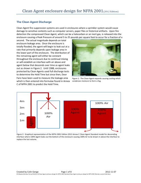
The <strong>Clean</strong> <strong>Agent</strong> Discharge<br />
<strong>Clean</strong> <strong>Agent</strong> fire suppression systems are used in <strong>enclosure</strong>s where a sprinkler system would cause<br />
damage to sensitive contents such as computer servers, paper files or historical artifacts. Upon fire<br />
detection the compressed <strong>Clean</strong> <strong>Agent</strong>, which can be a halocarbon or an inert gas, is released into the<br />
<strong>enclosure</strong> causing a Peak Pressure of around 5 to 25 pounds per square foot to occur <strong>for</strong> a fraction of a<br />
second. The actual magnitude depends on total<br />
<strong>enclosure</strong> leakage area. Once the <strong>enclosure</strong> is<br />
totally flooded, the agent will begin to leak out at a<br />
rate that primarily depends upon leakage area in<br />
the lower part of the <strong>enclosure</strong>. The distribution of<br />
the remaining agent will either be constant<br />
throughout the <strong>enclosure</strong> due to continual mixing<br />
or will establish an interface with air above and<br />
agent below that descends over time as agent leaks<br />
out as shown in Figure 2. Until 1988, <strong>enclosure</strong>s<br />
protected by <strong>Clean</strong> <strong>Agent</strong>s used full discharge tests<br />
to determine the Hold Time but since then, Door<br />
Fans have been used to measure the leakage area<br />
which is then entered into <strong>for</strong>mulae found in Annex<br />
C of <strong>NFPA</strong> <strong>2001</strong> to predict the Hold Time.<br />
Figure 1: The <strong>Clean</strong> <strong>Agent</strong> expands causing cooling which<br />
condenses moisture to <strong>for</strong>m a fog.<br />
Figure 2: Graphical representation of the <strong>NFPA</strong> <strong>2001</strong> <strong>Edition</strong> <strong>2012</strong> Annex C <strong>Clean</strong> <strong>Agent</strong> Standard model <strong>for</strong> descending<br />
interface where 100% <strong>Agent</strong> leaks out the bottom of the <strong>enclosure</strong> causing 100% Air to be drawn in above the interface to<br />
replace the lost volume.<br />
Created by Colin Genge Page 1 of 8 <strong>2012</strong>-11-07<br />
M:\Masters\Articles-Fire by Rt\<strong>2012</strong>-10 <strong>Clean</strong> <strong>Agent</strong> <strong>enclosure</strong> <strong>design</strong> <strong>for</strong> <strong>NFPA</strong> <strong>2001</strong> <strong>Retrotec</strong>\<strong>Clean</strong> <strong>Agent</strong> <strong>enclosure</strong> <strong>design</strong> <strong>for</strong> <strong>NFPA</strong> <strong>2001</strong> <strong>Retrotec</strong> version Draft.docx
Under-prediction of Peak Pressure<br />
It is common practice <strong>for</strong> Peak Pressure<br />
calculations to be done <strong>for</strong> inert agents but<br />
not <strong>for</strong> halocarbon agents and that is a big<br />
problem since they can produce as much<br />
Peak Pressure as inert agents. Peak<br />
Pressure varies over time depending on the<br />
ratio between the leakage rate and the<br />
volume of the <strong>enclosure</strong> (leak to volume<br />
ratio, or LVR). In a typical halocarbon agent<br />
discharge as shown in Figure 3, the Peak<br />
Pressure increases with <strong>enclosure</strong> tightness<br />
since tightness determines the increasing<br />
Hold Times shown in the legend. Formulae<br />
<strong>for</strong> calculating Peak Pressure may be<br />
provided by agent manufacturers. Although<br />
Figure 3: Typical halocarbon discharge showing Peak Pressure increasing<br />
with <strong>enclosure</strong> tightness (longer Hold Times)<br />
Peak Pressure is referred to by the <strong>NFPA</strong> <strong>2001</strong> Standard, the standard does not yet provide guidance on<br />
how it is to be calculated.<br />
A 5 year research project, carried out to provide a validated prediction model <strong>for</strong> Peak Pressure based<br />
on LVR, involving the author and many of the industry manufacturers (including: Fike, 3M, DuPont,<br />
Ansul, Kidde Fenwal, Chemetron, <strong>Retrotec</strong>), has uncovered many important facts about <strong>Clean</strong> <strong>Agent</strong><br />
discharge pressures and the Peak Pressure <strong>for</strong>mulae previously used to predict pressure values during<br />
<strong>enclosure</strong> <strong>design</strong> and testing. These facts include:<br />
1. Existing inert agent <strong>for</strong>mulae under-predict Peak Pressure<br />
2. Under certain conditions, halocarbon agents can produce as much Peak Pressure as inert agents<br />
3. Peak Pressures from Halocarbons are extremely dependent upon humidity<br />
Results of the project were published in the Fire Suppression Systems Association (FSSA) Pressure Relief<br />
Vent (PRV) Area Guide.<br />
Sufficient data was gathered to more accurately predict the Peak Pressure <strong>for</strong> all agents.<br />
Figure 4 shows the new curve (in white) developed <strong>for</strong> inert agent Peak Pressure versus Leak to Volume<br />
Ratio (LVR). Notice how the existing <strong>for</strong>mulae (dashed lines) all under-predict the Peak Pressure<br />
expected at a given LVR over the typical Peak Pressure values from 250 to 500 Pa. Figure 5 shows the<br />
results of testing of Peak Pressures versus LVR <strong>for</strong> all tested inert agents in the research.<br />
Figure 4: Peak Pressure is a function of LVR (Leakage to Volume Ratio). Existing <strong>for</strong>mulae all under-predict at typical Peak<br />
Pressure values (250 to 500 Pa).<br />
Created by Colin Genge Page 2 of 8 <strong>2012</strong>-11-07<br />
M:\Masters\Articles-Fire by Rt\<strong>2012</strong>-10 <strong>Clean</strong> <strong>Agent</strong> <strong>enclosure</strong> <strong>design</strong> <strong>for</strong> <strong>NFPA</strong> <strong>2001</strong> <strong>Retrotec</strong>\<strong>Clean</strong> <strong>Agent</strong> <strong>enclosure</strong> <strong>design</strong> <strong>for</strong> <strong>NFPA</strong> <strong>2001</strong> <strong>Retrotec</strong> version Draft.docx
Figure 5: Peak Pressure curves <strong>for</strong> all tested inert agents.<br />
A second leakage area must now be measured<br />
<strong>NFPA</strong><strong>2001</strong>, <strong>2012</strong> <strong>Edition</strong> Section 5.1.2.2 (28) now requires a “specified <strong>enclosure</strong> pressure limit” which<br />
will, in turn, dictate the Minimum Allowable Leakage Area <strong>for</strong> the <strong>enclosure</strong>. This Leakage Area can be<br />
provided by unintentional <strong>enclosure</strong> leakage and/or the area of any dampers that will be open during<br />
the discharge period. The Enclosure Integrity Procedure in Annex C has also been changed to require<br />
the measurement of two leakage area values, one used <strong>for</strong> the calculation of the Hold Time and another<br />
used <strong>for</strong> evaluating Peak Pressure during discharge. These values must be measured after the <strong>enclosure</strong><br />
has been completed. The new leakage area measurement is now necessary to fulfill the new<br />
requirement in Section 5.1.2.2 (10) that states “an estimate of the maximum positive pressure and the<br />
maximum negative pressure” during the <strong>Clean</strong> <strong>Agent</strong> discharge must be made. Section 5.3.7 states “If<br />
the developed pressures present a threat to the structural strength of the <strong>enclosure</strong>, venting shall be<br />
provided to prevent excessive pressures”. Clearly it would be extremely bad news to find out that a<br />
completed <strong>enclosure</strong> needed to have a Pressure Relief Vent (PRV) installed a few days be<strong>for</strong>e<br />
occupancy, but <strong>for</strong>tunately the <strong>design</strong>er can run calculations in advance using the new Peak Pressure<br />
equations that have come out of the research project to determine whether or not a PRV is likely to be<br />
needed and alter the <strong>design</strong> using the tips presented later in this article.<br />
It is no longer sufficient to simply specify a PRV of the correct size - its leakage rate must also be<br />
measured after installation to ensure the vent both opens at the correct pressure and has a large<br />
enough leakage path to outdoors to prevent the Peak Pressure from exceeding the “specified <strong>enclosure</strong><br />
pressure limit”. The 2008 <strong>Edition</strong> requires this new second measurement which can be done using the<br />
same Annex C Enclosure Integrity Procedure but with different set-up conditions. The same Door Fan<br />
equipment can often be used but users may find they need higher fan output to test at 50 Pa instead of<br />
the previous 10 Pa, and the need to test with the PRV’s open.<br />
Created by Colin Genge Page 3 of 8 <strong>2012</strong>-11-07<br />
M:\Masters\Articles-Fire by Rt\<strong>2012</strong>-10 <strong>Clean</strong> <strong>Agent</strong> <strong>enclosure</strong> <strong>design</strong> <strong>for</strong> <strong>NFPA</strong> <strong>2001</strong> <strong>Retrotec</strong>\<strong>Clean</strong> <strong>Agent</strong> <strong>enclosure</strong> <strong>design</strong> <strong>for</strong> <strong>NFPA</strong> <strong>2001</strong> <strong>Retrotec</strong> version Draft.docx
Optimizing Peak Pressure and Hold Time per<strong>for</strong>mance<br />
<strong>Clean</strong> agent discharges can produce damaging peak <strong>enclosure</strong> pressures that increase as total <strong>enclosure</strong><br />
leakage area decreases. Simply providing a lot of <strong>enclosure</strong> leakage area to solve the Peak Pressure<br />
problem creates another problem because Hold Times decrease as the leakage area increases. One<br />
solution is to add a Pressure Relief Vent (PRV) that will provide increased leakage to reduce the peak<br />
<strong>enclosure</strong> pressure only during discharge; the <strong>enclosure</strong> can then be made tight to provide the specified<br />
Hold Time. Another solution is to carefully consider the <strong>design</strong> parameters that affect Peak Pressure<br />
and Hold Time so that both requirements are met without using PRVs. Even if this <strong>design</strong> ef<strong>for</strong>t still<br />
results in the need <strong>for</strong> PRVs, optimizing the <strong>enclosure</strong> will increase the level of fire protection and<br />
possibly allow the use of smaller PRVs since more passive protection will be built in.<br />
Ironically, many inert agent protected <strong>enclosure</strong>s have PRVs installed where they are not needed while<br />
other <strong>enclosure</strong>s (protected by both inert and halocarbon agents) need PRVs but they are not installed.<br />
This situation can be resolved by using the new Enclosure Integrity evaluation procedure from Annex C<br />
of <strong>NFPA</strong> <strong>2001</strong> along with the new Peak Pressure <strong>for</strong>mulae. Adding PRVs is costly, sometimes impossible<br />
and often a source of unwanted risk, since they may fail to open and could damage the <strong>enclosure</strong>.<br />
Understanding the factors that affect the relationship between Peak Pressure and Hold Time will allow<br />
<strong>for</strong> <strong>design</strong>s without PRVs that easily pass both criteria. Invariably a few simple changes to the <strong>enclosure</strong><br />
will dramatically improve the suppression system’s per<strong>for</strong>mance and also save the installer from having<br />
to resolve difficult <strong>design</strong> problems in a last minute panic when the <strong>enclosure</strong> fails one or more of the<br />
acceptance criteria which typically occurs just prior to occupancy.<br />
Selection of Specified Enclosure Pressure Limit<br />
Formulae have been used <strong>for</strong> over a decade to predict Peak Pressures and to size PRVs <strong>for</strong> thousands of<br />
<strong>enclosure</strong>s without damaging those <strong>enclosure</strong>s. Since the 5 year research project showed that the<br />
actual peak pressures exceeded those predicted by the previously used <strong>for</strong>mulae by at least 100%, and<br />
many of those <strong>enclosure</strong>s were discharge tested with inert agents, it is safe to say that a wide range of<br />
<strong>enclosure</strong>s handled 500 Pa of Peak Pressure with ease. This has also been verified with the use of a high<br />
output fan to pressurize <strong>enclosure</strong>s where we have noticed no effects at 500 Pa. We can there<strong>for</strong>e<br />
assume that a double sided wall, securely fastened top and bottom, will handle 500 Pa and that 500 Pa<br />
can be used as a “specified <strong>enclosure</strong> pressure limit” which is the maximum pressure the <strong>enclosure</strong> can<br />
be subjected to without damage. If in doubt, test a wall section under the chosen “specified <strong>enclosure</strong><br />
pressure limit” using a high pressure Door Fan.<br />
While thicker walls can take more pressure as shown in Figure 6, False Ceilings can only take about 50 Pa<br />
so they must be protected from pressures higher than that with vented tiles. Ensure the False Ceiling<br />
has at least 5% open area to prevent it from being dislodged as the discharge vents upwards.<br />
Created by Colin Genge Page 4 of 8 <strong>2012</strong>-11-07<br />
M:\Masters\Articles-Fire by Rt\<strong>2012</strong>-10 <strong>Clean</strong> <strong>Agent</strong> <strong>enclosure</strong> <strong>design</strong> <strong>for</strong> <strong>NFPA</strong> <strong>2001</strong> <strong>Retrotec</strong>\<strong>Clean</strong> <strong>Agent</strong> <strong>enclosure</strong> <strong>design</strong> <strong>for</strong> <strong>NFPA</strong> <strong>2001</strong> <strong>Retrotec</strong> version Draft.docx
Figure 6: Wall Strength versus maximum allowable pressure in pounds per square foot <strong>for</strong> walls of different construction type<br />
reproduced from Reference 2<br />
Selecting an appropriate Hold Time<br />
After a typical 10 second discharge <strong>for</strong> halocarbons or 60 seconds <strong>for</strong> inert agents, the Hold Time begins.<br />
Even though this time has almost always been specified as 10 minutes, there was no specific <strong>NFPA</strong><br />
requirement until the 2008 <strong>Edition</strong> when the words “a minimum period of 10 minutes or <strong>for</strong> a time<br />
period to allow <strong>for</strong> response by trained personnel” were added to Section 5.6. Is “10 minutes” always<br />
the correct Hold Time? The <strong>design</strong>er must consider what the “time period to allow <strong>for</strong> response by<br />
trained personnel” will actually be because much longer Hold Times are required <strong>for</strong> remote sites or<br />
those with heavy fuel loads while much shorter Hold Times can be considered <strong>for</strong> small <strong>enclosure</strong>s that<br />
are manned 24-7. Reducing this Hold Time to 6 minutes <strong>for</strong> a small 1,250 cubic foot <strong>enclosure</strong> and to 3<br />
minutes <strong>for</strong> a 350 cubic foot <strong>enclosure</strong> would solve one of the most costly and pernicious problems that<br />
installers face, where getting these <strong>enclosure</strong>s tight enough to pass the 10 minute requirement becomes<br />
virtually impossible.<br />
Enclosure <strong>design</strong> tips<br />
The following <strong>design</strong> tips have the potential to do one or more of the following:<br />
o reduce installation costs<br />
o reduce risk of damage created by discharge pressures<br />
o ease maintenance<br />
o improve fire protection<br />
o reduce the risk of smoke damage<br />
The tips are meant to be considered during the <strong>design</strong> phase. The installed per<strong>for</strong>mance of the PRVs<br />
must be checked during installation to ensure they open at the correct pressure, in the correct direction<br />
and that the free vent area of the entire vent path falls within the specification. A very different leakage<br />
test, with PRVs closed, is per<strong>for</strong>med to ensure adequate retention time.<br />
1. Specify sealing of the walls to the upper slab. Extending walls to the upper slab and sealing<br />
them airtight is the only defense against fire and smoke entering from outside the <strong>enclosure</strong>.<br />
Created by Colin Genge Page 5 of 8 <strong>2012</strong>-11-07<br />
M:\Masters\Articles-Fire by Rt\<strong>2012</strong>-10 <strong>Clean</strong> <strong>Agent</strong> <strong>enclosure</strong> <strong>design</strong> <strong>for</strong> <strong>NFPA</strong> <strong>2001</strong> <strong>Retrotec</strong>\<strong>Clean</strong> <strong>Agent</strong> <strong>enclosure</strong> <strong>design</strong> <strong>for</strong> <strong>NFPA</strong> <strong>2001</strong> <strong>Retrotec</strong> version Draft.docx
Refer to C-1.2.1 (2) in <strong>NFPA</strong><strong>2001</strong> which states “…<strong>enclosure</strong>s absent of any containing barriers<br />
above the false ceiling, are not within the scope of Annex C” meaning the <strong>enclosure</strong> will be<br />
difficult to test and verify.<br />
2. Place nozzles to flood the entire <strong>enclosure</strong> with agent. The higher the initially flooded height<br />
the leakier the <strong>enclosure</strong> can be, producing less Peak Pressure but yielding longer Hold Times.<br />
Typically, the small savings generated by flooding only to the bottom of a false ceiling are more<br />
than offset by the increased air sealing costs needed to ensure adequate Hold Time, and may<br />
also <strong>for</strong>ce the inclusion of PRVs more often. If a False Ceiling is needed, specify nozzles above<br />
the ceiling; that’s how virtually all systems are <strong>design</strong>ed in Europe.<br />
3. Use an automatic door closing system. Doors often get wedged or propped open when the<br />
<strong>enclosure</strong> is in use. This practice impairs the clean agent system’s ability to put the fire out. A<br />
better solution is an automatic door release mechanism that will close the doors whenever the<br />
first alarm sounds. Choose a mechanism that will close the door when it is de-energized so it is<br />
failsafe.<br />
4. If a False Ceiling is specified, require air sealing of lower leaks first until the specified Hold<br />
Time is reached and then seal leaks above the False Ceiling up to the Peak Pressure Limit. The<br />
air leakage determination will require measuring upper and lower leaks separately as described<br />
in Section C.2.7.2 and shown in Figure 7.<br />
Figure 7: One Door Fan depressurizes the room while the second depressurizes above the ceiling so the pressure<br />
across the ceiling is zero allowing the lower fan to measure the room leaks separate from above ceiling leaks.<br />
5. Increase the initial concentration of agent an additional 15% over <strong>design</strong> concentration if<br />
continual mixing will occur, to ensure a long enough Hold Time. If air handlers continue to run<br />
during the Hold Time, then continual mixing is certain but even equipment cooling fans or<br />
thermal effects can be sufficient to cause continual mixing. Increasing the gap between the<br />
initial and final concentration in the continual mixing case has the<br />
same effect as making the room taller in the descending interface<br />
case. For non-mixing cases, the agent is allowed to drain out until<br />
it hits the protected equipment which is typically at 60 to 75% of<br />
the <strong>enclosure</strong> height allowing 40 to 25% of the agent respectively<br />
to run out be<strong>for</strong>e the equipment is no longer protected. If<br />
additional agent were not added, only 15% of the agent would<br />
have to be lost be<strong>for</strong>e the equipment loses its protection, since<br />
the standard requires that the final concentration at the end of<br />
the Hold Time at the top of the protected equipment be not less<br />
than 85% of the <strong>design</strong> concentration. The latest version of the<br />
<strong>NFPA</strong> <strong>2001</strong> standard uses an integration <strong>for</strong>mula that increases<br />
the Hold Time prediction somewhat but it is still extremely<br />
important to add this additional agent otherwise the <strong>enclosure</strong><br />
will fail the Hold Time after only 15% of the total weight of agent is lost.<br />
Figure 8: As agent is lost, air<br />
continually mixes with the<br />
agent to provide the same<br />
concentration everywhere in<br />
the <strong>enclosure</strong>.<br />
Created by Colin Genge Page 6 of 8 <strong>2012</strong>-11-07<br />
M:\Masters\Articles-Fire by Rt\<strong>2012</strong>-10 <strong>Clean</strong> <strong>Agent</strong> <strong>enclosure</strong> <strong>design</strong> <strong>for</strong> <strong>NFPA</strong> <strong>2001</strong> <strong>Retrotec</strong>\<strong>Clean</strong> <strong>Agent</strong> <strong>enclosure</strong> <strong>design</strong> <strong>for</strong> <strong>NFPA</strong> <strong>2001</strong> <strong>Retrotec</strong> version Draft.docx
6. If no mixing will occur, keep the height of the protected equipment to a minimum. If the<br />
equipment height exceeds 75% of <strong>enclosure</strong> height, continual mixing may be the only way to<br />
ensure a reasonable retention time.<br />
Pressure Relief Vent (PRV) tips<br />
If PRVs must be installed, there are several guidelines to follow to optimize their per<strong>for</strong>mance:<br />
Install vents as high as possible so that the lighter air, not the denser agent, is vented.<br />
Vents should open at pressures no lower than 50 Pa to ensure they don’t open unintentionally<br />
under normal HVAC pressures and no higher than 100 Pa so the pressure is vented early enough<br />
to prevent it from building up.<br />
Ensure the correct direction <strong>for</strong> venting with the PRV is specified. Inert agent discharges always<br />
create positive pressures and must have venting out of the <strong>enclosure</strong> but halocarbons may<br />
create positive and/or negative pressures creating a need to be vented in either direction or<br />
both depending on the agent and the humidity.<br />
All PRVs should be inspected annually to confirm they will open according to their specifications<br />
and to verify that the vent path to the outdoors has not been accidently restricted which is quite<br />
common as evidenced by the sign shown in Figure 9.<br />
Figure 9: The sign says "DO NOT OBSTRUCT", because it is very likely the vent path will be<br />
obstructed thus the vent path must be checked regularly.<br />
Peak Pressure evaluation tips<br />
PRVs that are <strong>design</strong>ed to open at a certain pressure must be tested prior to and/or after installation to<br />
verify they open at the prescribed pressure. 125 Pa is the pressure generally used to test PRVs because<br />
it is representative of the Peak Pressures that may be encountered. This pressure can be imposed upon<br />
Created by Colin Genge Page 7 of 8 <strong>2012</strong>-11-07<br />
M:\Masters\Articles-Fire by Rt\<strong>2012</strong>-10 <strong>Clean</strong> <strong>Agent</strong> <strong>enclosure</strong> <strong>design</strong> <strong>for</strong> <strong>NFPA</strong> <strong>2001</strong> <strong>Retrotec</strong>\<strong>Clean</strong> <strong>Agent</strong> <strong>enclosure</strong> <strong>design</strong> <strong>for</strong> <strong>NFPA</strong> <strong>2001</strong> <strong>Retrotec</strong> version Draft.docx
the damper in a test box, or the entire <strong>enclosure</strong> can be pressurized, or a temporary pressure box can be<br />
constructed around the damper <strong>for</strong> testing purposes. A large flow at a fairly high pressure will be<br />
required to test these vents in their open position, so consider testing them in a test box. Once the<br />
position at test pressure of 125 Pa is determined, the vanes must be locked in that position while the<br />
damper leakage area is tested. If installed in a test box where there are no bias pressures, it can be<br />
tested in the direction of intended venting. If installed in the <strong>enclosure</strong>, it should be tested in both<br />
directions to compensate <strong>for</strong> any bias pressures and to achieve a more accurate test due by increasing<br />
the amount of data collected. Ensure the PRV is tested in the flow direction that will occur during<br />
discharge. There are dual acting PRVs that will open in both directions but their free vent area differs<br />
with respect to direction, so they must be tested in both directions to see how open they are at 125 Pa.<br />
Reduced need <strong>for</strong> air-sealing and PRVs<br />
The 2008 and new <strong>2012</strong> editions of <strong>NFPA</strong> <strong>2001</strong> reduce the need <strong>for</strong> air sealing and relief vents. In many<br />
cases, the slightly more complex procedure proposed by <strong>Retrotec</strong> that was accepted into the Enclosure<br />
Integrity Procedure of <strong>NFPA</strong> <strong>2001</strong> will identify when <strong>enclosure</strong>s will per<strong>for</strong>m better than the older more<br />
conservative <strong>for</strong>mula dictated. This means 10 to 40% less air-sealing to be per<strong>for</strong>med and Pressure<br />
Relief Vents will have to be installed a lot less often, saving money on both counts.<br />
Table 1: Comparison of the Hold Time and Peak Pressure calculations <strong>for</strong> 3 <strong>Clean</strong> <strong>Agent</strong>s in a 2200 cubic foot <strong>enclosure</strong><br />
<strong>Agent</strong> Concentration<br />
Leakage<br />
area<br />
Min. Height Old <strong>NFPA</strong><br />
Hold Time | Peak Pressure<br />
New <strong>NFPA</strong><br />
Hold Time | Peak Pressure<br />
All FAIL All PASS<br />
DuPont FM-200®<br />
7% 29 sq in 8.5 ft 9.3 min. 382 Pa 10.4 min. 247 Pa<br />
3M Novec1230®<br />
4.5% 43 sq in 7.5 ft 9.7 min. 319 Pa 10.4 min. 217 Pa<br />
Argon 40% 166 sq in 7.0 ft 7.3 min. 373 Pa 10.3 min. 247 Pa<br />
The example in Table 1 of a 2200 cubic foot <strong>enclosure</strong>, 10 feet high and protected with three popular<br />
agents, shows how the new standard’s test procedure yields both longer retention times and lower peak<br />
pressures. In the example, the old <strong>for</strong>mulae would fail both the Hold Time requirement of 10 minutes<br />
and a 250 Pa Peak Pressure limit in each case but pass it in each case with the new <strong>for</strong>mulae. The old<br />
<strong>for</strong>mulae assumed a square root relationship between pressure and flow, represented by a 0.5<br />
exponent whereas most tight <strong>enclosure</strong>s have exponents closer to 0.65.<br />
References<br />
1. <strong>NFPA</strong> <strong>2001</strong> <strong>Edition</strong><strong>2012</strong>, "Standard on <strong>Clean</strong> <strong>Agent</strong> Fire Extinguishing Systems”, National Fire<br />
Protection Association, Quincy, MA, <strong>2012</strong>.<br />
2. Table 2 from: Paper 17; HOTWC 2005; NIST SP 984-3, “Pressure Dynamics of <strong>Clean</strong> <strong>Agent</strong><br />
Discharges”, Robin, M. L.; Forssell, E. W.; Sharma, V.,<br />
http://fire.nist.gov/bfrlpubs/fire05/PDF/f05077.pdf<br />
3. Paper 18; HOTWC 2005; NIST SP 984-3, “Preventing Excessive Enclosures Pressures During <strong>Clean</strong><br />
<strong>Agent</strong> Discharges”, Genge, C., http://fire.nist.gov/bfrlpubs/fire05/PDF/f05059.pdf<br />
DuPontand FM-200® are registered trademarks or trademarks of E. I. du Pont de Nemours and Company or its affiliates.<br />
Created by Colin Genge Page 8 of 8 <strong>2012</strong>-11-07<br />
M:\Masters\Articles-Fire by Rt\<strong>2012</strong>-10 <strong>Clean</strong> <strong>Agent</strong> <strong>enclosure</strong> <strong>design</strong> <strong>for</strong> <strong>NFPA</strong> <strong>2001</strong> <strong>Retrotec</strong>\<strong>Clean</strong> <strong>Agent</strong> <strong>enclosure</strong> <strong>design</strong> <strong>for</strong> <strong>NFPA</strong> <strong>2001</strong> <strong>Retrotec</strong> version Draft.docx