

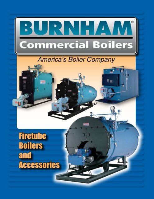
Firetube Boilers and Accessories
Firetube Boilers and Accessories
Firetube Boilers and Accessories

Create successful ePaper yourself
Turn your PDF publications into a flip-book with our unique Google optimized e-Paper software.
America’s Boiler Company<br />
<strong>Firetube</strong><br />
<strong>Boilers</strong><br />
<strong>and</strong><br />
<strong>Accessories</strong>
Contents<br />
PRODUCT PAGE<br />
Series 3 Packaged <strong>Firetube</strong> Boiler.................................................................................................................. 3<br />
Series 3 Shock Proof Boiler........................................................................................................................... 9<br />
Series 3 Packaged <strong>Firetube</strong> Boiler “Ohio Special”......................................................................................... 11<br />
Anticipated Efficiencies................................................................................................................................. 13<br />
Wetback vs. Hard Refractory Dryback Design.............................................................................................. 15<br />
Series 4S 4-Pass Wetback Scotch Boiler..................................................................................................... 17<br />
Low Nox Boiler............................................................................................................................................ 21<br />
Series 4F Forced Draft Firebox Boiler........................................................................................................... 23<br />
Series 4F-40 ................................................................................................................................................ 27<br />
Series 4F-45 ................................................................................................................................................ 29<br />
Series 4F-50 ................................................................................................................................................ 31<br />
Series 4F Forced Draft <strong>Firetube</strong> Boiler “Ohio Special” ................................................................................. 33<br />
Series 4N Natural Draft Firebox Boiler ......................................................................................................... 35<br />
Series 4NP Natural Draft Firebox Boiler ....................................................................................................... 43<br />
C Series Compact Package Boiler ................................................................................................................ 45<br />
Component Summary Information .............................................................................................................. 49<br />
Chemical Feed System ................................................................................................................................ 52<br />
Bypass <strong>and</strong> Shot Feed Systems .................................................................................................................. 54<br />
Boiler Feedwater System ............................................................................................................................ 56<br />
Condensate Return System ........................................................................................................................ 57<br />
Blowdown Heat Recovery System ............................................................................................................... 58<br />
Bottom Blowdown Tank .............................................................................................................................. 60<br />
Flash Separator ........................................................................................................................................... 62<br />
Bottom Blowdown Separator ...................................................................................................................... 64<br />
Conductivity Controller ............................................................................................................................... 66<br />
Water Softener Systems BS & BP ............................................................................................................... 68<br />
Horizontal <strong>and</strong> Integral Deaerators .............................................................................................................. 70<br />
Engineering <strong>and</strong> Application Data Index ...................................................................................................... 73
Series 3<br />
Packaged <strong>Firetube</strong> Boiler
Series 3 - Packaged <strong>Firetube</strong> Boiler<br />
Save Thous<strong>and</strong>s Of Dollars<br />
Over The Life Of Your Boiler<br />
Long-term energy <strong>and</strong> maintenance efficiencies are the<br />
focus of Burnham quality engineering. When choosing<br />
a boiler, it’s a good idea to select a product with these<br />
features in order to reduce enormous hidden costs down<br />
the road. Review our wetback versus dryback literature for<br />
cost savings.<br />
Boiler Costs Is Not Jus A First Year Proposition<br />
With any ordinary boiler, expenses such as fuel,<br />
maintenance, <strong>and</strong> repair costs can escalate as the years<br />
go on. Burnham packaged boilers are designed to diminish<br />
these significant expenditures.<br />
Burnham’s High Life-Cycle Efficiency<br />
While most competitive boilers can give fuel-to-steam<br />
efficiencies of 80% or over—when they’re new—how<br />
consistently can they be expected to maintain this level<br />
of operation? Burnham wetback boiler performance will<br />
not drop due to deteriorating rear refractory, leaking door<br />
baffles <strong>and</strong> seals, <strong>and</strong> heat-stressed rear tube sheet<br />
as can happen with some drybacks. Easy access is a<br />
necessity for those with heavy refractory, since they need<br />
frequent <strong>and</strong> expert maintenance.<br />
The Burnham Wetback Saves<br />
Big Money On Maintenance<br />
Over the life of a dryback, brittle refractory baffling <strong>and</strong><br />
rear door gasketing will require continuous monitoring,<br />
maintenance, <strong>and</strong> replacement, costing thous<strong>and</strong>s upon<br />
thous<strong>and</strong>s of dollars. These built-in maintenance costs can<br />
eventually equal or exceed the original cost of the boiler.<br />
As refractory deteriorates, leaking hot gas causes boiler<br />
efficiency to drop until the condition is noticed <strong>and</strong> the<br />
repairs can be made. Expensive flue temperature alarms<br />
are offered with some drybacks to monitor this dangerous<br />
<strong>and</strong> costly potentiality. The rear door itself can become<br />
heat-distorted, requiring an expensive replacement. In<br />
addition, boiler downtime during repairs can mean crippling<br />
losses.<br />
This waste of time <strong>and</strong> money is eliminated with the<br />
Burnham Wetback. The actively functional water jacket<br />
eliminates the need for: refractory wall, rear door, rear<br />
door inspection <strong>and</strong> sealing, door swing space, <strong>and</strong> flue<br />
temperature alarm. These costly maintenance headaches<br />
are gone, while boiler performance is increased. Burnham<br />
has only a small, inexpensive refractory area in the burner<br />
area, for burner mounting. The rear access door liner is a<br />
ceramic fiber insert that contains no refractory.<br />
The furnace <strong>and</strong> rear turnaround area are cool running, fully<br />
wetbacked radiant heat transfer surfaces. They promote good<br />
internal water circulation <strong>and</strong> rapid heat absorption. There is no<br />
need for the forced internal circulation pumps often specified to<br />
cool the rear tube-sheets <strong>and</strong> drybacks.<br />
The Burnham Wetback Is Built To Last<br />
Typical dryback boilers have a common rear tubesheet that<br />
exp<strong>and</strong>s <strong>and</strong> contracts at different rates adjacent to each<br />
tube pass, stressing tube ends <strong>and</strong> increasing the likelihood<br />
of leaks. Additionally, the heavy refractory used in some<br />
drybacks reflects intense heat to the rear tube ends <strong>and</strong> tube<br />
sheet, accelerating their deterioration. In attempts to stop<br />
leaking, the rear ends of tubes have sometimes been welded.<br />
Cleaning or tube replacement involves opening both the front<br />
<strong>and</strong> rear covers <strong>and</strong> resealing them when the job is done.<br />
Usually, if tubes have been welded at the ends, the welds must<br />
be burned out, the tube sheet repaired (or a new segment<br />
welded in) <strong>and</strong> the new tubes welded.<br />
These costly expenditures are not an issue with the Burnham<br />
Scotch Marine: separate rear tube sheets from each pass<br />
to exp<strong>and</strong> <strong>and</strong> contract at its own rate without tube-to-sheet<br />
stress. Tubes are rolled <strong>and</strong> flared in low-pressure units; <strong>and</strong><br />
rolled, flared <strong>and</strong> beaded in high-pressure units. No welding<br />
of tubes is permitted, nor is it necessary. Any eventual tube<br />
replacement is simply a mechanical operation, no welding<br />
involved. The end result is less cost <strong>and</strong> less headache.
Boiler<br />
Model<br />
Shell<br />
Diam.<br />
Series 3 - Ratings <strong>and</strong> Data<br />
Gross Output Net Rating<br />
BHP MBH<br />
LBS/<br />
HR<br />
Steam<br />
MBH<br />
Steam<br />
Sq. Ft.<br />
Water,<br />
MBH<br />
Heating<br />
Surface<br />
Sq.<br />
Ft.<br />
F.S.<br />
Sq.<br />
Ft.<br />
W.S.<br />
Firing Rate<br />
Gas,<br />
MBH<br />
Oil,<br />
GPH*<br />
Furn.<br />
Vol.,<br />
Cu.<br />
Ft.<br />
Water Content<br />
Lbs.<br />
Steam<br />
Lbs.<br />
Water<br />
Approx. Wt.<br />
Dry, Lbs.<br />
0 8 0 1, 9 1, 80 1,011 , 11 1,16 00 0 1,67 1 /11 1 .8 1,760 ,18 ,700 , 00<br />
0 8 0 1,67 1,7 1, 90 , 76 1, 6 0 80 ,09 1 /1 17.1 , 0 .701 , 00 ,700<br />
60 8 60 ,009 ,070 1, 60 6, 99 1,7 7 00 , 00 18/17 19. ,76 , ,700 , 00<br />
70 70 , , 1 1,819 7, 80 ,0 7 0 90 ,9 0 1/ 0 7.8 , 8 ,160 , 00 6, 00<br />
80 80 ,678 ,760 ,079 8,66 , 9 00 , 8 / 0. ,67 ,6 1 ,900 6,700<br />
90 90 ,01 ,10 , 9 9,7 7 ,6 0 0 00 ,766 7/ .0 ,060 ,1 6, 00 7, 00<br />
100 100 , 8 , 0 , 99 10,8 0 ,911 00 ,18 0/ 8 .8 , ,711 6,900 7,700<br />
1 66 1 ,18 , 1 , 8 1 , ,6 8 6 69 , 0 8/ 1.9 , 8 6,67 8,700 9, 00<br />
1 0 66 1 0 ,0 1 ,17 ,898 16, , 66 7 0 8 6, 76 / 7.7 6,660 7,9 7 9,700 10,600<br />
17 66 17 ,8 8 6,0 0 , 8 18,9 0 ,09 87 970 7, / 9 .1 7,7 8 9, 10,900 11,600<br />
00 66 00 6,69 6,900 ,198 1,6 8 ,8 1,000 1,110 8, 69 60/ 6 8.8 8,8 9 10, 19 1 , 00 1 , 00<br />
0 78 0 8, 69 8,6 6, 98 7,07 7, 77 1, 0 1, 60 10, 61 7 /70 86.6 11,17 1 ,98 1 , 00 18,600<br />
00 78 00 10,0 10, 0 7,797 , 89 8,7 1, 00 1,6 0 1 , 00 90/8 99.1 1 , 1 16,6 9 18,100 1, 00<br />
0 90 0 11,716 1 ,07 9,096 7,901 10,188 1,7 0 1,900 1 ,6 10 /98 11 . 1 , 9 19, 0 1,000 ,700<br />
00 90 00 1 , 90 1 ,800 10, 96 , 17 11,6 ,000 ,17 16,7 8 1 0/11 1 .7 16,76 ,1 , 00 6,100<br />
00 10 00 16,7 8 17, 0 1 ,99 ,1 7 1 , , 00 ,71 0,9 1 0/1 0 1 .0 18, 1 ,788 7, 00 0,600<br />
600 10 600 0,08 0,700 1 , 9 6 ,9 7 17, 6 ,000 , 60 ,106 180/168 17 . ,1 8 8, 81 1, 00 , 00<br />
700 10 700 , ,1 0 18,19 7 ,80 0, 77 , 00 ,80 9, 19 10/196 19 .8 ,767 ,00 ,700 9,700<br />
800 108 800 6,780 7,600 0,79 86,6 , 87 ,000 , 9 , 7 0/ 0 . ,9 ,76 ,900 ,900<br />
900 11 900 0,1 8 , 17 , 00 97,61 N/A , 00 ,90 7,660 69/ 78 0,89 N/A 7,800 6,600<br />
1000 1 1,000 , 76 , 00 ,990 108, 9 N/A ,000 , 0 1,8 6 00/ 80 09 , 7 N/A 1,600 10 , 00<br />
Note: Dimensions <strong>and</strong> Data are Not for Construction Purposes <strong>and</strong> are Subject to Change without Notice<br />
15-30<br />
PSI<br />
150<br />
PSI
• Large, fully waterbacked furnace tube assures<br />
complete combustion <strong>and</strong> heat absorption<br />
without flame impingement.<br />
• Three gas passes extract maximum usable heat<br />
from the fuel while maintaining optimum flow for<br />
forced draft firing.<br />
• Fully waterbacked reversing chamber effectively<br />
absorbs radiant heat into the water,<br />
keeping tube ends <strong>and</strong> rear of<br />
boiler cooler than those of<br />
hot-running drybacks.<br />
Front View<br />
• Ready access to tubes through rugged front door <strong>and</strong> rear covers<br />
makes routine cleaning easier <strong>and</strong> less costly than with drybacks.<br />
• Burner does not have to be disturbed.<br />
• No inner air baffle door to contend with.<br />
• Unlike dryback boilers, securing the doors on a Burnham wetback boiler<br />
requires no specialized skills or expensive repair materials. It is a simple<br />
process which can be done with in-house personnel <strong>and</strong> performed with<br />
minimal downtime.<br />
• No delicate expensive baffle tiles or door seals to replace.<br />
6<br />
Rear View
It All Adds Up To Significant Cost-Performance Advantage.<br />
What do all these features <strong>and</strong> specifications mean? More<br />
savings for you! Our Packaged Wetback <strong>Firetube</strong> boilers are<br />
designed for long-term efficiency <strong>and</strong> economical operation,<br />
making Burnham your cost-performance leader!<br />
The Series 3 matches burner to boiler, providing a fuelefficient,<br />
low-maintenance package. Maintenance costs<br />
can be further controlled in your boiler room with optional<br />
accessories. Such options include state-of-the-art annunciator<br />
systems, custom-designed to monitor all boiler <strong>and</strong> burner<br />
interlocks vital to your specific installation. They provide instant<br />
readouts of both normal <strong>and</strong> abnormal operating conditions.<br />
These features will pinpoint the cause of unscheduled<br />
shutdowns; reducing maintenance time <strong>and</strong> skill required.<br />
7<br />
• Forced-draft firing with oil (No. 2, 4, 5, or 6),<br />
gas or combination gas/oil<br />
• Low or high pressure steam or water<br />
• Highly efficient three-pass design<br />
• Fully waterbacked primary heating surfaces<br />
• Separate rear tube sheets for longer service life<br />
• Wetback design allows easy front <strong>and</strong> rear access<br />
• No expensive refractory or door replacement as<br />
with some drybacks.
Series 3 — St<strong>and</strong>ard Equipment<br />
Boiler:<br />
Three pass full wetback, packaged firetube type, constructed<br />
in accordance with requirements of the ASME Code Section<br />
IV for 30 psi <strong>and</strong> 125 psi water or 15 psi steam; Section I<br />
for higher pressure steam. All units are registered with the<br />
National Board.<br />
Boiler tubes are exp<strong>and</strong>ed <strong>and</strong> flared in low pressure boilers;<br />
exp<strong>and</strong>ed <strong>and</strong> beaded in high pressure boilers. Turbulator<br />
baffles are not used in tubes. Separate second <strong>and</strong> third pass<br />
rear tube sheets allow safe expansion <strong>and</strong> contraction.<br />
Waterbacked rear turnaround promotes rapid internal<br />
circulation <strong>and</strong> reduces gas temperatures at entrance to<br />
second pass, reducing tube end stress.<br />
Easy opening hinged, insulated front flue doors with<br />
lightweight closure provide full access to all tubes. A 16inch<br />
diameter bolted rear access door with observation port<br />
provides access to the boiler furnace. Rear tube access is<br />
provided by removing light weight gasketed door(s) installed<br />
in the rear smokebox. No elaborate seals are used.<br />
A manhole is furnished as st<strong>and</strong>ard on water <strong>and</strong> low<br />
pressure steam boilers sizes 3-125 <strong>and</strong> larger; on high<br />
pressure steam boilers sizes 3-70 <strong>and</strong> larger.<br />
H<strong>and</strong>hole washouts are provided for easy inspection <strong>and</strong><br />
cleaning of waterside surfaces.<br />
All steam boilers provided with a dry pan to ensure dry steam.<br />
A feedwater diffuser is provided on high pressure boilers. All<br />
water boilers are equipped with a dip tube at supply outlet<br />
<strong>and</strong> diffuser at return inlet.<br />
The round flanged vertical smoke outlet is equipped with a<br />
locking quadrant damper. All boilers are provided with an<br />
enameled steel jacket over 2 inches of fiberglass insulation,<br />
<strong>and</strong> lifting lugs.<br />
The boiler is mounted on a heavy duty structural steel base<br />
with extended skid <strong>and</strong> burner platform for protection of the<br />
burner during shipment <strong>and</strong> rigging.<br />
St<strong>and</strong>ard Trim <strong>and</strong> Controls:<br />
Steam: 157 pump control/low water cut-off with alarm<br />
contacts–piped with quick opening blowoff valve. Gauge<br />
glass set with h<strong>and</strong>-operated <strong>and</strong> try cocks. Steam pressure<br />
gauge—4 1/2 inch dial on sizes 100 hp <strong>and</strong> smaller, 6<br />
inch dial on larger sizes. L404C manual reset high limit<br />
pressuretrol <strong>and</strong> appropriate firing rate control when required.<br />
Manual reset probe auxiliary low water cut-off.<br />
ASME side outlet safety valve(s).<br />
Water: 63M manual reset low water cut-off with 30 psi<br />
units, 150 low water cut-off with higher pressure units–piped<br />
with quick opening blowoff valve. Combination pressure/<br />
temperature gauge–3 1/2 inch dial on 100 hp <strong>and</strong> smaller. On<br />
larger sizes a 6 inch combination pressure/altitude gauge <strong>and</strong><br />
5 inch dial temperature gauge. L4006A operating aquastat<br />
<strong>and</strong> L4006E manual reset high limit aquastat <strong>and</strong> appropriate<br />
firing rate control when required.<br />
ASME side outlet safety valve(s).<br />
Burner Equipment:<br />
Burner mounts to front head of boiler with no elaborate seals.<br />
Factory packaged units available with forced draft burners for all<br />
commonly used fuels–gas, all grades of oil–No. 2 through No.<br />
6–<strong>and</strong> combination gas/oil. Choice of pressure or air atomizing<br />
burners for No. 2 oil–air atomizing on heavy oil. Gas burners are<br />
available for either natural or LP gas.<br />
Refer to burner data sheets for st<strong>and</strong>ard burner equipment <strong>and</strong><br />
operating sequence.<br />
<strong>Accessories</strong> <strong>and</strong> Optional Equipment:<br />
<strong>Accessories</strong> <strong>and</strong> optional equipment available at extra cost,<br />
including, but not limited to:<br />
• Solid-state annunciators<br />
• Alternate or additional water level controls or low water cut-offs<br />
• Built-in tankless heater coils—low-pressure boilers only<br />
• Motorized or pneumatic feed valves<br />
• Surface skimmers <strong>and</strong> blowoff valves<br />
• Bottom blowdown valves <strong>and</strong> drain valves<br />
• Feed stop <strong>and</strong> check valves<br />
• Sequence draft controls<br />
• Lead/lag sequencing systems<br />
• Boiler Feed systems<br />
• Low NOx burners<br />
• Deaerators<br />
• Water Softeners<br />
• Chemical Feed systems<br />
• Blowdown systems<br />
• Sample Coolers<br />
8<br />
©2009 Burnham Commercial - Lancaster, PA<br />
Phone: 1-888-791-3790<br />
www.burnhamcommercial.com
Series 3<br />
Shock Proof Boiler<br />
Eliminate any thermal shock concerns with a Series 3-SP Shock Proof hot water boiler package.<br />
Our low pressure, 15 psi steam boiler is equipped with a full capacity coil type<br />
heat exchanger capable of 125 psi maximum water pressure.<br />
9
Eliminate Thermal Shock…<br />
Eliminate any thermal shock concerns with our Series -SP Shock<br />
Proof hot water boiler package. This boiler design uses our reliable<br />
Series that incorporates a high steam space volume that can<br />
easily accommodate the industries largest full capacity coil. The<br />
Series wetback design <strong>and</strong> low volumetric furnace release<br />
rates allow easy firing <strong>and</strong> a prolonged boiler life. When properly<br />
commissioned <strong>and</strong> maintained, your shock -proof packaged boiler<br />
will last for many years.<br />
Shock Proof Features<br />
Ratings <strong>and</strong> Data<br />
Shock Proof Benefits<br />
• Specially designed heat exchanger tubes which are highly resistant<br />
to corrosion <strong>and</strong> erosion.<br />
• Specially constructed head<br />
• Flanged supply <strong>and</strong> return<br />
• Coil trim package included, consists of inlet <strong>and</strong> outlet pressure<br />
gauges, inlet <strong>and</strong> outlet thermometers <strong>and</strong> coil side safety valves.<br />
• Equipped with a full capacity coil type heat exchanger designed for<br />
1 psi maximum water pressure.<br />
Performance criteria based on 10 psi boiler operating pressure<br />
Flanges orientation may be horizontal, as illustrated, or vertical. Consult factory.<br />
• No steam side water make up, no steam side<br />
accessories are required.<br />
• There is only one initial steam side water treatment required.<br />
Since the steam side is sealed, expensive maintenance hours,<br />
auxiliary equipment <strong>and</strong> chemicals are eliminated. A clean steam<br />
side will make your boiler run more efficiently.<br />
• The hot system water flows only through the tubes of the heat<br />
exchanger eliminating thermal stresses <strong>and</strong> hot water maintenance<br />
issues on the boiler side.<br />
Model Number 3L125SP 3L150SP 3L200SP 3L250SP 3L300SP 3L350SP 3L400SP 3L500SP 3L600SP 3L800SP<br />
Output @ Coil Nozzle, MBH, 4,184 5,021 6,695 8,369 10,043 11,716 13,390 16,738 20,085 26,780<br />
GPM @ 20°F Delta T/180°F/200°F 420 503 670 840 1,008 1,180 1,340 1,680 2,015 2,755<br />
Delta P thru coil at above flow rate, PSI 5 5 5 5 5 5 5 5 5 5<br />
Head Flange Size, 150# ANSI 4” 4” 5” 6” 6” 6” 8” 8” 8” 8”<br />
10<br />
Lancaster, PA 17601<br />
Phone: 888-791- 790<br />
www.burnhamcommercial.com
Series 3 Packaged <strong>Firetube</strong> Boiler — “Ohio Special”<br />
Three pass full wetback, packaged firetube, constructed in<br />
accordance with requirements of the ASME code, section IV<br />
for 1 -psi steam; Section 1 for higher pressure steam. All units<br />
are registered with the National Board.<br />
Boiler tubes are exp<strong>and</strong>ed <strong>and</strong> flared in low-pressure boilers;<br />
exp<strong>and</strong>ed <strong>and</strong> beaded in high pressure boilers. Separate<br />
second <strong>and</strong> third pass rear tube sheets allow safe expansion<br />
<strong>and</strong> contraction.<br />
Waterbacked rear turnaround promotes rapid internal<br />
circulation <strong>and</strong> reduces gas temperatures at entrance to<br />
second pass, reducing tube end stress.<br />
Easy opening hinged, insulated front flue doors with bolted<br />
closure provide full access to all tubes. A 16-inch diameter<br />
bolted rear access door with observation port provides access<br />
to the boiler furnace. Removing lightweight gasketed door(s)<br />
installed on the rear smokebox provides rear tube access. No<br />
elaborate seals are used. A manhole is furnished as st<strong>and</strong>ard<br />
on all Ohio Special <strong>Boilers</strong>, 100 through hp. H<strong>and</strong>hole<br />
washouts are provided for easy inspection <strong>and</strong> cleaning of<br />
waterside surfaces.<br />
All steam boilers are provided with a dry pan to ensure<br />
drysteam. A feedwater diffuser is provided on high-pressure<br />
boilers.<br />
The round-flanged vertical smoke outlet is equipped with a<br />
locking quadrant damper. All boilers are provided with an<br />
enameled steel jacket over 2 inches of fiberglass insulation<br />
<strong>and</strong> lifting lugs.<br />
Ratings <strong>and</strong> Data<br />
Shell Diameter<br />
Ratings Gross Output - BHP<br />
Gross Output - MBH<br />
Gross Output - LBS/HR<br />
Net Rating - MBH<br />
Net Rating - Sq. Ft.<br />
Safety Valve (15 PSIG) - LBS/HR<br />
Safety Valve (150 PSIG) - LBS/HR<br />
Heating Surface - Sq. Ft.<br />
Fireside<br />
Waterside<br />
<strong>Firetube</strong>s Number<br />
Diameter - Inches<br />
Furnace Volume - Cu. Ft.<br />
Diameter - Inches<br />
Firing Rate 100 BTU Gas - MBH<br />
140 MBTU/Gal. Oil - GPH<br />
150 MBTU/Gal. Oil - GPH<br />
11<br />
The boiler is mounted on a heavy-duty structural steel base<br />
with extended skid <strong>and</strong> burner platform for protection of the<br />
burner during shipment <strong>and</strong> rigging.<br />
St<strong>and</strong>ard Trim <strong>and</strong> Controls<br />
1 7 pump control/low water cut-off with alarm, contactspiped<br />
with quick opening blowoff valve. Gauge glass set<br />
with h<strong>and</strong> operated gauge <strong>and</strong> tri-cocks. Steam pressure<br />
gauge: -1/ inch dial on 100 HP, 6 inch dial on larger sizes.<br />
L 0 A operating pressuretrol, L 0 C manual reset high limit<br />
pressuretrol <strong>and</strong> appropriate firing rate control when required.<br />
Manual reset probe auxiliary low water cut-off. ASME side<br />
outlet safety valve(s).<br />
100X 125X 150X 175X 200X 225X<br />
100<br />
, 8<br />
, 0<br />
, 99<br />
10,8 9<br />
, 0<br />
,906<br />
8<br />
8<br />
6<br />
.<br />
1<br />
,18<br />
, 1<br />
, 9<br />
1 , 6<br />
, 1<br />
,88<br />
8<br />
8<br />
6<br />
.<br />
1 0<br />
,0 1<br />
,17<br />
,898<br />
16,<br />
,17<br />
,8 8<br />
8<br />
8<br />
6<br />
.<br />
17<br />
,8 8<br />
6,0 7<br />
, 8<br />
18,9 1<br />
6,0 7<br />
6,8<br />
8<br />
8<br />
6<br />
.<br />
00<br />
6,69<br />
6,900<br />
,198<br />
1,6 8<br />
6,900<br />
7,811<br />
0. 0. 0. 0. 0. 0.<br />
,18<br />
9.9<br />
7.9<br />
, 0<br />
7.<br />
.9<br />
6, 77<br />
.8<br />
1.8<br />
7,<br />
.<br />
8.8<br />
8<br />
8<br />
6<br />
.<br />
8, 69<br />
9.8<br />
.8<br />
7,<br />
7,76<br />
,8 8<br />
, 66<br />
7,76<br />
8,787<br />
8<br />
8<br />
6<br />
.<br />
9, 1<br />
67.<br />
6 .8
Dimensions (in inches)<br />
A - Base Width<br />
B - Furnace Center<br />
C - Overall High Pressure Supply Connection<br />
Overall Low Pressure Supply Connection<br />
D - Width over Trim<br />
E - Width over Jacket<br />
F - Base to N.W.L.<br />
G - Overall Length<br />
H - Base Length<br />
J - Front to High Pressure Feed Connection<br />
K - Base Extension<br />
L - Flue Door Clearance<br />
M - Tube Removal Space<br />
N - High Pressure Supply Size<br />
Low Pressure Supply Size<br />
P - Shell Length over Flue Outlet<br />
Q - Front to Supply<br />
R - High Pressure Supply to Manway<br />
Low Pressure Supply to Manway<br />
S - Flue Outlet Flange Diameter<br />
T - Flue Inside Diameter<br />
U - Outside Flange to Center<br />
V - Floor to Flue Outlet Flange<br />
W - Floor to High Pressure Feed Connection<br />
X - Feed Connection Size<br />
Water Content<br />
LBS<br />
Gallons<br />
Approximate Shipping Weight<br />
Low Pressure (Dry) - LBS<br />
Low Pressure (Wet, N.W.L) - LBS<br />
High Pressure (Dry) - LBS<br />
High Pressure (Wet, N.W.L.) - LBS<br />
© 006 Burnham Commercial - Lancaster, PA<br />
Phone: 1-888-791- 790<br />
www.burnhamcommercial.com<br />
100X 125X 150X 175X 200X 225X<br />
38<br />
33-5/16<br />
76-5/8<br />
76-5/8<br />
69-1/4<br />
59-1/4<br />
59-3/4<br />
190-1/2<br />
159-3/4<br />
93-1/8<br />
35-3/4<br />
29-1/2<br />
125<br />
4” flg<br />
8” flg<br />
154-3/4<br />
60-1/8<br />
33<br />
33<br />
17<br />
13-3/8<br />
8-1/2<br />
74-3/8<br />
43-5/16<br />
1-1/4<br />
5,536<br />
664<br />
7,000<br />
12,450<br />
8,100<br />
13,550<br />
38<br />
33-5/16<br />
76-5/8<br />
76-5/8<br />
69-1/4<br />
59-1/4<br />
59-3/4<br />
190-1/2<br />
1<br />
159-3/4<br />
93-1/8<br />
35-3/4<br />
29-1/2<br />
125<br />
4” flg<br />
8” flg<br />
154-3/4<br />
60-1/8<br />
33<br />
33<br />
17<br />
13-3/8<br />
8-1/2<br />
74-3/8<br />
43-5/16<br />
1-1/4<br />
5,536<br />
664<br />
7,050<br />
12,450<br />
8,150<br />
13,550<br />
38<br />
33-5/16<br />
76-5/8<br />
76-5/8<br />
69-1/4<br />
59-1/4<br />
59-3/4<br />
190-1/2<br />
159-3/4<br />
93-1/8<br />
35-3/4<br />
29-1/2<br />
125<br />
4” flg<br />
8” flg<br />
154-3/4<br />
60-1/8<br />
33<br />
33<br />
17<br />
13-3/8<br />
8-1/2<br />
74-3/8<br />
43-5/16<br />
1-1/4<br />
5,536<br />
664<br />
7,100<br />
12,500<br />
8,200<br />
13,600<br />
38<br />
33-5/16<br />
76-5/8<br />
76-5/8<br />
69-1/4<br />
59-1/4<br />
59-3/4<br />
192-1/2<br />
159-3/4<br />
93-1/8<br />
35-3/4<br />
29-1/2<br />
125<br />
6” flg<br />
8” flg<br />
156-3/4<br />
60-1/8<br />
33<br />
33<br />
17<br />
15-1/2<br />
9-1/2<br />
74-3/8<br />
43-5/16<br />
1-1/2<br />
5,536<br />
664<br />
7,500<br />
12,950<br />
8,600<br />
14,050<br />
38<br />
33-5/16<br />
76-5/8<br />
76-5/8<br />
69-1/4<br />
59-1/4<br />
59-3/4<br />
192-1/2<br />
159-3/4<br />
93-1/8<br />
35-3/4<br />
29-1/2<br />
125<br />
6” flg<br />
8” flg<br />
156-3/4<br />
60-1/8<br />
33<br />
33<br />
17<br />
15-1/2<br />
9-1/2<br />
74-3/8<br />
43-5/16<br />
1-1/2<br />
5,536<br />
664<br />
7,650<br />
13,050<br />
8,750<br />
14,150<br />
38<br />
33-5/16<br />
76-5/8<br />
76-5/8<br />
69-1/4<br />
59-1/4<br />
59-3/4<br />
194-1/2<br />
159-3/4<br />
93-1/8<br />
35-3/4<br />
30-3/4<br />
125<br />
6” flg<br />
8” flg<br />
158-3/4<br />
60-1/8<br />
33<br />
33<br />
17<br />
17-1/2<br />
9-1/2<br />
74-3/8<br />
43-5/16<br />
1-1/2<br />
5,536<br />
664<br />
7,650<br />
13,050<br />
8,750<br />
14,150
Natural Gas<br />
BOILER<br />
SIZE<br />
100<br />
125<br />
150<br />
200<br />
250<br />
300<br />
350<br />
400<br />
500<br />
600<br />
700<br />
800<br />
1000<br />
#2 Oil<br />
BOILER<br />
SIZE<br />
100<br />
125<br />
150<br />
200<br />
250<br />
300<br />
350<br />
400<br />
500<br />
600<br />
700<br />
800<br />
1000<br />
Anticipated Efficiencies<br />
125% 50% 75% 100%<br />
10 # 125 # 10 # 125 # 10 # 125 # 10 # 125 #<br />
8 . 0<br />
81.00<br />
8 .00<br />
8 . 0<br />
81. 0<br />
8 .00<br />
8 . 0<br />
8 .00<br />
8 . 0<br />
8 .00<br />
8 .00<br />
8 . 0<br />
8 . 0<br />
78. 0<br />
77.00<br />
78.00<br />
79.00<br />
78.00<br />
78. 0<br />
78. 0<br />
78.00<br />
79.00<br />
79. 0<br />
79. 0<br />
80.00<br />
80.00<br />
8 . 0<br />
8 .00<br />
8 .00<br />
8 . 0<br />
8 .00<br />
8 . 0<br />
8 .00<br />
8 .00<br />
8 .00<br />
8 .00<br />
8 . 0<br />
8 . 0<br />
8 . 0<br />
80. 0<br />
79.00<br />
80.00<br />
80. 0<br />
79. 0<br />
80.00<br />
80. 0<br />
80.00<br />
81.00<br />
81.00<br />
81. 0<br />
81. 0<br />
81. 0<br />
1<br />
8 . 0<br />
8 .00<br />
8 .00<br />
8 . 0<br />
8 .00<br />
8 . 0<br />
8 .00<br />
8 .00<br />
8 .00<br />
8 . 0<br />
8 . 0<br />
8 . 0<br />
8 . 0<br />
81.00<br />
79. 0<br />
80. 0<br />
81.00<br />
80.00<br />
80. 0<br />
81.00<br />
80. 0<br />
81. 0<br />
8 .00<br />
8 .00<br />
8 .00<br />
8 .00<br />
8 . 0<br />
8 .00<br />
8 .00<br />
8 . 0<br />
8 .00<br />
8 . 0<br />
8 .00<br />
8 .00<br />
8 .00<br />
8 . 0<br />
8 . 0<br />
8 . 0<br />
8 . 0<br />
81.00<br />
79. 0<br />
80. 0<br />
81. 0<br />
80.00<br />
80. 0<br />
81.00<br />
80. 0<br />
81. 0<br />
8 .00<br />
8 .00<br />
8 .00<br />
8 .00<br />
125% 50% 75% 100%<br />
10 # 125 # 10 # 125 # 10 # 125 # 10 # 125 #<br />
8 . 0 81. 0 86. 0 8 . 0 86. 0 8 .00 86. 0 8 .00<br />
8 .00 80.00 8 .00 8 .00 8 . 0 8 . 0 8 . 0 8 . 0<br />
8 .00 81.00 86.00 8 .00 86. 0 8 . 0 86. 0 8 . 0<br />
86.00 8 .00 87.00 8 .00 87.00 8 . 0 87.00 8 . 0<br />
8 .00 81. 0 8 . 0 8 .00 8 . 0 8 .00 8 . 0 8 .00<br />
8 . 0 81. 0 86.00 8 . 0 86.00 8 . 0 86.00 8 . 0<br />
8 . 0 8 .00 86. 0 8 .00 86. 0 8 . 0 86. 0 8 . 0<br />
8 .00 81. 0 86.00 8 . 0 86. 0 8 .00 86. 0 8 .00<br />
86.00 8 .00 87.00 8 .00 87. 0 8 .00 87. 0 8 .00<br />
86.00 8 . 0 87. 0 8 . 0 87. 0 8 .00 87. 0 8 .00<br />
86. 0 8 . 0 87. 0 8 . 0 88.00 8 . 0 88.00 8 . 0<br />
87.00 8 .00 88.00 8 .00 88.00 8 . 0 88.00 8 . 0<br />
87.00 8 .00 88.00 8 .00 88.00 8 . 0 88.00 8 . 0
ThERMAL EFFICIENCY<br />
The effectiveness of the boiler as a heat exchanger. It is the ability of the boiler to exchange heat through tubes <strong>and</strong><br />
furnace, by radiation, conduction <strong>and</strong> convection, to the transfer medium (water). A few of the factors affecting thermal<br />
efficiency are heating surface, tube number <strong>and</strong> diameter, furnace tube length <strong>and</strong> diameter.<br />
COMBuSTION EFFICIENCY<br />
This is a measure of the ability of the burner to effectively <strong>and</strong> completely burn the fuel, coupled with the thermal<br />
efficiency of the boiler. Burners requiring high amounts of excess air to provide flame stability will be less efficient.<br />
Combustion efficiency does not take into account heat loss to the surrounding air through the boiler jacket <strong>and</strong> piping.<br />
FuEL TO STEAM EFFICIENCY<br />
Sometimes referred to as overall efficiency. This is a ratio of heat output to heat input. This includes boiler jacket <strong>and</strong><br />
piping losses to the surrounding environment. It is the percent of useable heat in the steam (or hot water) compared to<br />
the heat input supplied by the burner. It is also defined as the combustion efficiency less boiler jacket <strong>and</strong> piping loss<br />
(radiation <strong>and</strong> convection losses). Since fuel-to-steam efficiency reflects the portion of actual usable heat supplied to<br />
the system, it is most useful when comparing performance of similar equipment, or when doing fuel savings analysis.<br />
BOILER RATINGS<br />
Ratings may be expressed in the following units:<br />
BHP = Boiler Horsepower. One BHP is the evaporation of . lbs of 1 °F water per hour into dry saturated<br />
steam at the same temperature.<br />
BHP =<br />
BTUh<br />
, 7 BTUh/BHP<br />
BTU = British Thermal Units: that quantity of heat required to raise one (1) lb. of water one<br />
(1) degree on the Fahrenheit scale. BTUh = BTU/hr.<br />
MBH = 1000 BTUh<br />
PPH = Pounds of steam per hour<br />
PPH =<br />
MBH<br />
0.970 MBH/PPH<br />
Gross Rating – The full output of a boiler actually available to the heating or process system at the outlet nozzle.<br />
The Commercial Steel Boiler Industry catalogs gross output as 80% of input.<br />
Net Ratings – The net connected design load that can be supplied with heat by a boiler of given output, allowing<br />
for normal system piping losses <strong>and</strong> pickup from a cold start. Since steam system piping losses may be<br />
expected to be larger than for water systems, <strong>and</strong> steam boilers require greater heat input from a cold start<br />
than water boilers before heat flows to the system, steam net ratings for automatic fired boilers are slightly<br />
lower in relation to gross output than water net ratings. H<strong>and</strong> fired net water <strong>and</strong> steam ratings are equal<br />
<strong>and</strong> are lower in relation to gross output in order to provide ample allowance for rapid pickup from a<br />
banked fire.<br />
MBH net water = Gross MBH x 0.87<br />
MBH net steam = Gross MBH x 0.776<br />
Square Foot Ratings – Net ratings based on a heat emission rate of 0 BTUh per square foot of radiation for<br />
steam, <strong>and</strong> 1 0 BTUh per square foot for water.<br />
Steam Net MBH Water net MBH<br />
Square Feet Net Steam = Square Feet Net Water =<br />
0. MBH / sq. ft. 0.1 MBH / sq. ft.<br />
1
Wetback Design vs. Hard Refractory<br />
Dryback Design<br />
Why is a Wetback design better?<br />
Burnham’s three-pass wetback design has a rear water<br />
wall, which separates the primary heating surface of the<br />
combustion chamber from the rear tube sheet. The water<br />
jacket eliminates the need for a refractory wall <strong>and</strong> rear<br />
door swing space behind the boiler, as well as costly<br />
refractory maintenance.<br />
The rear water wall eliminates the need for gasketing,<br />
which is vulnerable to the temperature generated in the<br />
rear of the turnaround area. A wetback design boiler not<br />
only overcomes these expensive deficiencies, but it has<br />
great overall efficiency <strong>and</strong> virtually maintenance-free<br />
construction.<br />
A Burnham boiler will cost you less over the lifetime<br />
of the boiler because it is better by design!<br />
Some Points to Remember:<br />
Wetback Advantages<br />
• Wetback boilers have separate tube sheets between all major temperature changes.<br />
• The rear access door is constructed of lightweight ceramic fiber<br />
• The rear doors require no cool-down period <strong>and</strong> can be opened immediately<br />
• No space consuming area required for the swing door<br />
• The split rear flue doors are easily removed<br />
• Efficiency is readily maintainable because the design of the boiler promotes complete <strong>and</strong> even circulation of<br />
flue gases<br />
Dryback Disadvantages<br />
• Flue gas temperature differential of 1 00F-1600F between the second <strong>and</strong> third passes creates damaging stresses<br />
on the single tube sheet. The cost of rear door refractory replacement (approximately every three years) will<br />
drastically increase operating costs, as well as the costs associated with yearly rear door gasket replacement.<br />
• Opening <strong>and</strong> resealing the rear door is time consuming <strong>and</strong> requires a -hour cool down period prior to opening<br />
• The heavy refractory may sag on the davit <strong>and</strong> must be rigged back into place. Heavy jacks or expensive rigging<br />
may be required just to open <strong>and</strong> close the rear doors<br />
• Exposing the refractory to hot flue gases can cause erosion <strong>and</strong> destroy the baffle; resulting in the uneven<br />
circulation of flue gases <strong>and</strong> lower efficiency<br />
• Rear refractory walls radiate unabsorbed heat, leading to external heat loss<br />
1
WhAT IS FuEL-TO-STEAM EFFICIENCY AND IS IT IMPORTANT?<br />
Fuel-to-steam efficiency is very important because it is the only true measure of overall packaged boiler operational<br />
efficiency. True fuel-to-steam efficiency takes into account radiation <strong>and</strong> convection heat losses, which less reputable<br />
manufacturers may ignore. We suggest purchasing your boiler from a manufacturer who guarantees fuel-to-steam<br />
efficiency in the performance of your entire packaged boiler. Be wary of misleading efficiency terms, such as “thermal<br />
efficiency” or “combustion efficiency”. Contact your local Burnham Commercial sales representative for further definition.<br />
MAINTAINABLE EFFICIENCY VS. ATTAINABLE EFFICIENCY<br />
When looking at efficiency as criteria for purchasing a boiler, especially fuel-to-steam efficiency, the manufacturer’s<br />
design efficiency sets theoretical fuel costs while operation efficiency determines actual fuel costs. There is a difference<br />
between attainable efficiency <strong>and</strong> maintainable efficiency. Correct burner adjustments are the key to maintainable<br />
efficiency. It is a compromise between the optimum <strong>and</strong> the practical. Good burner tuning is achievable only with<br />
a good burner design <strong>and</strong> a good burner/boiler package.<br />
WILL A DRYBACK BOILER COST MORE TO OWN?<br />
The answer is simple…Yes! The high cost of maintenance is the biggest consideration in overall efficiency in a dryback<br />
design. Consider this example: an average 00 HP boiler operating under normal conditions with a conservative<br />
lifespan of years. Our surveys have shown that during this boiler’s lifetime the rear door refractory would be<br />
replaced about 8 times (roughly every three years). Also, assuming the boiler is opened only once a year for inspection,<br />
regasketing of the rear door would occur times.<br />
How much cheaper is the hard refractory backed boiler?<br />
So, somebody is offering a hard refractory backed boiler design for less money than a wetback design! While it may<br />
make your initial capital investment costs look great, what does it do to your pocketbook in the long run?<br />
Let’s take a look....<br />
Average cost for replacing rear door hard refractory: $6,000<br />
Average cost of regasketing the rear door: $ 00<br />
Apply these costs to the average lifespan of the boiler:<br />
$6,000 X 8 = $ 8,000<br />
$ 00 X = $1 , 00<br />
Compare the costs of replacing the rear door gasket of your wetback design:<br />
$ 0 X = $7 0<br />
The difference between the hard refractory dry back maintenance <strong>and</strong> the wetback maintenance is<br />
$60, 00 - $7 0 = $ 9,7 0.<br />
Now comes the shocking part...for the same amount of money spent in dryback maintenance:<br />
YOu COuLD hAVE PuRChASED<br />
A NEW BuRNRhAM WETBACK BOILER!<br />
16
Series 4S<br />
4-Pass Wetback Scotch Boiler<br />
17
America’s Boiler Company<br />
The Burnham Commercial Series S four-pass wetback<br />
scotch boiler was designed using our 1 0+ years of boiler<br />
experience <strong>and</strong> is sold <strong>and</strong> serviced through the largest<br />
<strong>and</strong> most experienced network of sales representatives in<br />
the country. With a complete commercial product offering<br />
<strong>and</strong> unmatched sales <strong>and</strong> technical support, it’s no wonder<br />
why we are America’s Boiler Company!<br />
Why Choose the Series 4S?<br />
• The design incorporates positive water flow circulation<br />
<strong>and</strong> maximum heat transfer to maximize ratings.<br />
• The h<strong>and</strong>hole clean-outs are placed for ease of<br />
servicing.<br />
• The access door is<br />
constructed of durable,<br />
lightweight vacuum formed<br />
ceramic fiber—the door liner<br />
weighs less than 0 pounds!<br />
• All external trim piping is<br />
designed <strong>and</strong> installed in<br />
accordance with the ASME<br />
Code <strong>and</strong> is certified by an<br />
independent inspection agency for compliance.<br />
• The fiberglass insulated steel jacket is finish painted<br />
with high gloss Burnham blue enamel.<br />
• The front <strong>and</strong> rear full-sized hinged access doors are<br />
st<strong>and</strong>ard <strong>and</strong> secured with non-corrosive brass nuts.<br />
• The UL approved packaged burners are trimmed <strong>and</strong><br />
wired to assembled gas trains.<br />
4-Pass Wetback Scotch Boiler<br />
• The heavy steel base provides adequate stability<br />
along with shipping <strong>and</strong> rigging protection.<br />
• It is completely packaged <strong>and</strong> ready for “same day”<br />
installation.<br />
• The sq.ft./hp rated design does not use turbulators<br />
or welded tube ends.<br />
• The multitude of QC checkpoints <strong>and</strong> stringent final<br />
inspection assures you of a quality product.<br />
• There are no proprietary parts or gaskets on the boiler<br />
trim or the burner.<br />
Latest Design Techniques<br />
The Series S uses the very latest design techniques<br />
<strong>and</strong> st<strong>and</strong>ards. Its furnace, the workhorse of the boiler,<br />
is designed for low volumetric release rates of no more<br />
than 1 6,000 btu/hr/cu.ft. The lower the release rates,<br />
the “easier” your boiler works. As your boiler works<br />
easier, less stress is put upon the steel, tube ends,<br />
refractory, etc., resulting in a longer lasting boiler. In<br />
addition to longevity, a larger furnace makes for ease<br />
in firing using any selected burner vendor. The Series<br />
S is also easily converted to a low NOx product when<br />
needed.<br />
Higher Efficiency<br />
The Burnham Series S design produces a higher<br />
efficiency due to the larger furnace <strong>and</strong> higher heat<br />
transfer design. To determine the efficiency of your next<br />
job, contact your local Burnham representative.<br />
4 Pass Wetback Scotch Boiler—To learn more about wetback versus dryback, please refer to our wetback literature<br />
18
Dimensions <strong>and</strong> Ratings<br />
100 125 150 175 200 250 300 350 400 500 600 700 800<br />
A 68 68 76 76 76 86 86 94 94 104 104 114 114<br />
B 84 85 93 93 93 103 103 111 111 121 121 131 131<br />
C 150 176 169 188 207 207 235 240 263 264 300 282 311<br />
Dimensions are approximate, see detailed drawings for more specific dimensions.<br />
Rating Data<br />
Boiler Size, HP 100 125 150 175 200 250 300 350 400 500 600 700 800<br />
Shell Diameter 62 62 70 70 70 70 78 88 88 98 98 108 108<br />
Gross Output, BHP 100 125 150 175 200 250 300 350 400 500 600 700 800<br />
Gross Output, MBH 3348 4184 5021 5858 6695 8369 10,043 11,716 13,390 16,738 20,085 23.433 26,780<br />
Gross Ouput, Lbs./Hr. 3450 4312.5 5175 6037.5 6900 8625 10,350 12,075 13,800 17,250 20,700 24,150 27,600<br />
Heating Surface, FS Sq. Ft.<br />
Firing Rate - Gas<br />
Gas - MBH<br />
Oil - GPH (140 MBTU/Gal.)<br />
Furnace Volume - Cu. Ft.<br />
Heat Releases Rate<br />
BTU/Hr./Cu. Ft.<br />
Water Content<br />
Flooded - Gal.<br />
NWL - Gal.<br />
Shipping Weight - Lbs.<br />
15/30 psi<br />
125/150 psi<br />
500<br />
4184<br />
29.9<br />
39<br />
107,618<br />
875<br />
779<br />
8,000<br />
8,900<br />
625<br />
5230<br />
37.4<br />
46<br />
112,686<br />
1,115<br />
995<br />
9,940<br />
10,400<br />
750<br />
6277<br />
44.8<br />
58<br />
108,471<br />
1,187<br />
1,019<br />
10,500<br />
11,700<br />
875<br />
7323<br />
52.3<br />
66<br />
111,565<br />
1,391<br />
1,187<br />
12,000<br />
13,200<br />
1000<br />
8369<br />
59.8<br />
73<br />
114,003<br />
1,606<br />
1,367<br />
13,200<br />
14,400<br />
19<br />
1250<br />
10,461<br />
74.7<br />
93<br />
112,617<br />
1,750<br />
1,487<br />
15,600<br />
19,000<br />
1500<br />
12,553<br />
89.7<br />
108<br />
116,193<br />
2,110<br />
1,786<br />
18,300<br />
21,600<br />
1750<br />
14,645<br />
104.6<br />
133<br />
110,011<br />
2,661<br />
2,266<br />
22,300<br />
21,600<br />
2000<br />
16,738<br />
119.6<br />
149<br />
112,491<br />
3,045<br />
2,601<br />
24,500<br />
27,600<br />
2500<br />
20,922<br />
149.4<br />
177<br />
118,528<br />
3,536<br />
2,818<br />
28,900<br />
32,300<br />
3000<br />
25,106<br />
179.3<br />
206<br />
121,670<br />
4,256<br />
3,405<br />
33,200<br />
37,100<br />
3500<br />
29,291<br />
2092<br />
219<br />
133,559<br />
4,747<br />
3,932<br />
38,300<br />
45,100<br />
4000<br />
33,475<br />
239.1<br />
246<br />
136,013<br />
5,431<br />
4,507<br />
42.500<br />
50,000
Lancaster, PA 17601<br />
Phone: 888-791- 790<br />
www.burnhamcommercial.com<br />
Series 4S St<strong>and</strong>ard Equipment<br />
Boiler:<br />
Four-pass full wetback firetube type, constructed in<br />
accordance with requirements of the ASME Code, Section<br />
IV for 0 PSI <strong>and</strong> 1 PSI water or 1 PSI steam; Section I<br />
for higher-pressure steam. All units are registered with the<br />
National Board.<br />
Turbulator baffles are not used in tubes. Separate rear tube<br />
sheets allow safe expansion <strong>and</strong> contraction.<br />
Waterbacked rear turnaround promotes rapid internal<br />
circulation <strong>and</strong> reduces gas temperatures at the entrance to<br />
the second pass, reducing tube end stress.<br />
Easy opening hinged, insulated front flue doors with light<br />
weight non-refractory closure provide full access to all tubes.<br />
A light weight 16-inch diameter bolted rear access door with<br />
observation port provides access to the boiler furnace. Rear<br />
tube access is provided by removing lightweight gasketed<br />
doors(s) installed on the rear smokebox. No elaborate seals<br />
are used.<br />
A manhole is furnished as st<strong>and</strong>ard. H<strong>and</strong>hole washouts<br />
are provided for easy inspection <strong>and</strong> cleaning of waterside<br />
surfaces.<br />
All steam boilers are provided with a dry pan to ensure dry<br />
steam. A feedwater diffuser is provided on high-pressure<br />
boilers. All water boilers are equipped with a dip tube at<br />
supply outlet <strong>and</strong> diffuser at return inlet.<br />
The round-flanged vertical smoke outlet is equipped with a<br />
quadrant damper. All boilers are provided with an enameled<br />
steel jacket installed over 2 inches of fiberglass insulation<br />
<strong>and</strong> lifting lugs.<br />
The boiler is mounted on a heavy-duty structural steel base<br />
with extended skid <strong>and</strong> burner platform for protection of the<br />
burner during shipment <strong>and</strong> rigging.<br />
St<strong>and</strong>ard Trim <strong>and</strong> Controls:<br />
Steam: 1 7 pump control/low water cut-off with alarm<br />
contacts—piped with quick opening blowoff valve. Gauge<br />
glass set with h<strong>and</strong>-operated gauge <strong>and</strong> try cocks. Steam<br />
pressure gauge—4 ½-inch dial on sizes 125 HP <strong>and</strong> smaller,<br />
6-inch dial on larger sizes. L 0 A operating pressuretrol,<br />
L 0 C manual reset high limit pressuretrol <strong>and</strong> appropriate<br />
firing rate control when required. Manual reset probe<br />
auxiliary low water cut-off.<br />
ASME side outlet safety valve(s).<br />
0<br />
Water: 6 M manual reset low water cut-off with 0 PSI<br />
units,<br />
150M low water cut-off with higher-pressure units—piped<br />
with quick opening blowoff valve. Combination pressure/<br />
temperature gauge—3 ½ inch dial on 125 HP <strong>and</strong> smaller.<br />
On larger sizes a 6-inch combination pressure/altitude<br />
gauge <strong>and</strong> -inch dial temperature gauge. L 006A operating<br />
aquastat <strong>and</strong> L 006E manual reset high limit aquastat <strong>and</strong><br />
appropriate firing rate control when required.<br />
ASME side outlet relief valve(s).<br />
Burner Equipment:<br />
Burner mounts directly to the front head of the boiler with no<br />
elaborate seals.<br />
Factory packaged units available with forced draft burners<br />
for all commonly used fuels—gas, all grades of oil—No. 2<br />
through No. 6—a combination gas/oil. Choice of pressure<br />
or air atomizing burners for No. 2 oil—air-atomizing burners<br />
for No. 2 oil—air atomizing on heavy oil. Gas burners are<br />
available for either natural or LP gas.<br />
Refer to burner data sheets for st<strong>and</strong>ard burner equipment<br />
<strong>and</strong> operating sequence.<br />
<strong>Accessories</strong> <strong>and</strong> Optional Equipment:<br />
<strong>Accessories</strong> <strong>and</strong> optional equipment available at extra cost,<br />
including, but not limited to:<br />
• Alternate or additional water level controls or low water<br />
cut-offs<br />
• Built-in tankless heater coils—low-pressure boilers only<br />
• Motorized or pneumatic feed valves<br />
• Surface skimmers <strong>and</strong> blowoff valves<br />
• Bottom blowdown valves <strong>and</strong> drain valves<br />
• Feed stop <strong>and</strong> check valves<br />
• Sequence draft controls<br />
• Lead/lag sequencing systems<br />
• Boiler Feed systems<br />
• Low NOx burners<br />
• Deaerators<br />
• Water Softeners<br />
• Chemical Feed systems<br />
• Blowdown systems<br />
• Sample Coolers
Low NOx<br />
1
America’s Boiler Company<br />
Burnham Commercial has been designing <strong>and</strong><br />
producing boilers for 1 0+ years, <strong>and</strong> we sell <strong>and</strong><br />
service through the largest <strong>and</strong> most experienced<br />
network of sales representatives in the country. Our<br />
representatives are capable of providing technical<br />
assistance, competent pricing, start-up, <strong>and</strong> long term<br />
servicing. It’s no wonder we are America’s Boiler<br />
Company!<br />
Low NOx Needs<br />
Being America’s Boiler Company, we know what<br />
burner vendors are looking for in boiler designs when<br />
it comes to reduced NOx combustion levels—large<br />
furnaces, high heat transfer, <strong>and</strong> low draft losses:<br />
• Large furnaces mean low volumetric release rates.<br />
• High heat transfer for the most efficient boiler for<br />
your application.<br />
• Less burner motor horsepower so less energy is<br />
used to operate your boiler.<br />
Lancaster, PA 17601<br />
Phone: 888-791- 790<br />
www.burnhamcommercial.com<br />
Low NOx<br />
Combining these three features contribute to an ideal<br />
low NOx package application.<br />
Our firebox design provides<br />
the largest furnace possible in a firetube, <strong>and</strong> our<br />
scotch boilers have some of the largest furnaces<br />
available in our market—meaning we can meet all<br />
your Low NOx needs.<br />
Important Design Considerations<br />
Our proven designs use the very latest low<br />
NOx techniques <strong>and</strong> st<strong>and</strong>ards. Our furnace,<br />
the workhorse of the boiler, is designed for low<br />
volumetric heat release. The lower the release rates,<br />
the “easier” your boiler works. As your boiler works<br />
easier, less stress is put upon the steel, tube ends,<br />
refractory, etc., resulting in a longer lasting boiler. In<br />
addition to longevity, a larger boiler makes for ease in<br />
firing using any selected burner vendor.<br />
Smaller furnaces are extremely susceptible to erratic<br />
flame patterns. Deformed flame patterns cause<br />
uneven heat distribution, uneven absorption <strong>and</strong><br />
localized hot spots, which can lead to overheating<br />
<strong>and</strong> over stressing. Our selections give the customer<br />
the choice of any of the major low NOx burner<br />
manufacturers. Because we have so many proven<br />
product design selections to choose from, we can<br />
custom fit any of our products to your boiler room.<br />
Burnham Commercial can offer you firebox, threepass<br />
or four-pass wetback scotch. We are<br />
the only manufacturer who can offer<br />
their packages complete with flue gas<br />
recirculation piping, when necessary. That<br />
eliminates extra design responsibility <strong>and</strong><br />
field installation costs.<br />
Proven Product Applications<br />
Unlike any other manufacturer, every Burnham<br />
Commercial Low NOx package is design application<br />
approved by our own Engineering Department <strong>and</strong><br />
our burner vendors’ Engineering <strong>and</strong> Applications<br />
Design Groups. Our 1 0+ years successful track<br />
record assures you that our products, <strong>and</strong> our vendor<br />
selection, are the best available.
Series 4F<br />
Forced Draft Firebox Boiler
Series 4F Forced Draft Firebox Boiler<br />
The Versatile Boiler<br />
The Burnham Commercial F forced draft steel<br />
firebox boiler is a consistent sales leader in the<br />
heating industry. Its compact <strong>and</strong> constructive<br />
design saves on installation, operation, <strong>and</strong><br />
maintenance.<br />
4F Saves on Installation<br />
The 4F is a compact boiler that fits where other<br />
designs of similar capacity cannot. Available for<br />
1 psi steam <strong>and</strong> 0 or 60 psi water*, the F<br />
can serve perfectly as the heart of almost any<br />
system. As a factory assembled, forced-draft fired<br />
boiler, this packaged unit does not require a tall,<br />
expensive vent stack or excessive jobsite time<br />
<strong>and</strong> labor.<br />
4F Saves in Operation<br />
• The furnace surrounds the flame with<br />
highly efficient waterbacked primary<br />
heat absorbing surfaces. This large<br />
combustion chamber is easy to fire<br />
<strong>and</strong> accommodates many forced-draft<br />
burners without flame impingement or<br />
other critical firing problems.<br />
• Forced draft firing makes the 4F inherently more<br />
efficient than boilers using outmoded atmospheric<br />
burners <strong>and</strong> gives you a feature that atmospheric<br />
units cannot offer: the option of burning gas or oil.<br />
• A dual fired burner allows you to burn the more<br />
economical fuel or the most readily available fuel<br />
at the flip of a switch <strong>and</strong> affords you leverage in<br />
negotiating fuel prices.<br />
• The F is an economical heat source, whether used<br />
singly or in multiples. In fact, F’s with modulating<br />
burners may be sequenced to operate in a step-fired<br />
system more cost effectively than a large number of<br />
space saver boilers when ongoing maintenance costs<br />
are considered.<br />
4F Saves on Maintenance<br />
• Superior design makes the F easy to clean <strong>and</strong><br />
maintain — requiring no special tools, materials, or<br />
skills.<br />
• Opening the front flue door allows firetubes to be<br />
brushed out quickly, unlike the watertubes used in<br />
some boilers which can be virtually impossible to<br />
clean.<br />
• Elaborate or expensive proprietary seals are not<br />
required to re-close the doors as with some boilers.<br />
• As a wetback boiler, there is no delicate or expensive<br />
rear refractory to maintain.<br />
*60-psi water boiler - consult factory for available sizes.
Dimensions (in Inches)<br />
Series 4F — Models 63 - 675<br />
4F Boiler Models 63 78 92 107 127 154 180 209 240 277 311 345 360 450 563 675<br />
A - Boiler Width 31 31 31 31 36-3/8 36-3/8 36-3/8 36-3/8 45-1/8 45-1/8 45-1/8 45-1/8 52-3/4 52-3/4 56-1/2 56-1/2<br />
B - Boiler Length 32 39 45-1/2 52-1/2 44-1/2 53 61 70 57 65 72-1/2 80 80-3/4 93-1/4 104-3/8 122-1/4<br />
C - Boiler Height 55-1/4 55-1/4 55-1/4 55-1/4 63-5/8 63-5/8 63-5/8 63-5/8 70-5/8 70-5/8 70-5/8 70-5/8 82-7/16 82-7/16 85-3/16 85-3/16<br />
D - Base Width 33-1/4 33-1/4 33-1/4 33-1/4 38-5/8 38-5/8 38-5/8 38-5/8 47-3/8 47-3/8 47-3/8 47-3/8 53-1/8 53-1/8 57 57<br />
E - Base Length 47-1/2 54-1/2 65 72 64 72-1/2 80-1/2 92-1/2 79-1/2 87-1/2 95 102-1/2 107-1/2 124 135-1/8 153<br />
F - Base Extension 15-1/2 15-1/2 19-1/2 19-1/2 19-1/2 19-1/2 19-1/2 22-1/2 22-1/2 22-1/2 22-1/2 22-1/2 26-3/4 30-3/4 30-3/4 30-3/4<br />
G - Front Smoke Box Height 27-5/16 27-5/16 27-5/16 27-5/16 29-7/16 29-7/16 29-7/16 29-7/16 35-1/8 35-1/8 35-1/8 35-1/8 38-1/2 38-1/2 41-9/16 41-9/16<br />
H - Front Smoke Box Depth 5-1/2 5-1/2 5-1/2 5-1/2 6-1/2 6-1/2 6-1/2 6-1/2 7-1/2 7-1/2 7-1/2 7-1/2 6-1/2 6-1/2 7-1/2 7-1/2<br />
J - Supply Location 13 13 13 13 16 16 16 16 19 19 19 19 28 28 28 28<br />
*K - Supply Size 4 4 4 4 6 6 6 6 6 8 8 8 8 10 10 10<br />
*L - Return Size - Steam 3 3 3 3 4 4 4 4 4 4 4 4 4 4 4 4<br />
M - Return Location 6-1/2 6-1/2 6-1/2 6-1/2 7 7 7 7 7 7 7 7 7-3/8 7-3/8 7-3/8 7-3/8<br />
N - Top Vent Collar Dia. 7 7 7 7 10 10 10 10 12 12 12 12 — — — —<br />
P - Rear Vent Collar Dia. — — — — — — — — — — — — 14 14 18 18<br />
Q - Rear Vent Collar Height 38 38 38 38 46-1/2 46-1/2 46-1/2 46-1/2 52 52 52 52 58-13/16 58-13/16 59-5/8 59-5/8<br />
R - Smoke Box Depth 9 9 9 9 12 12 12 12 14 14 14 14 16 16 20 20<br />
T - Top Vent Collar Height 42-1/2 42-1/2 42-1/2 42-1/2 52-1/2 52-1/2 52-1/2 52-1/2 59-1/4 59-1/4 59-1/4 59-1/4 66-5/16 66-5/16 69-1/8 69-1/8<br />
U - Tube Pull Space 32 39 45-1/2 52-1/2 44-1/2 53 61 70 57 65 72-1/2 80 81-1/2 94 105 123<br />
V - Supply Fitting Height 1-1/2 1-1/2 1-1/2 1-1/2 3-1/4 3-1/4 3-1/4 3-1/4 3-1/4 3-1/4 3-1/4 3-1/4 3-3/8 3-3/8 3-7/16 3-7/16<br />
W - Normal Water Line Height 43-3/4 43-3/4 43-3/4 43-3/4 51-1/2 51-1/2 51-1/2 51-1/2 58 58 58 58 69-3/16 69-3/16 72 72<br />
*3” <strong>and</strong> 4” are IPS female thread, 6” <strong>and</strong> larger are flanged. 150# bolt pattern. Specifications, Dimensions Data Subject to Change without Notice
Dimensions (in Inches)<br />
The Complete Boiler Room Supplier<br />
4F Boiler Models 827 993 1157 1323 1654 1985 2315 2645 3075<br />
A - Boiler Width 64 64 70 70 76 82 82 82 96<br />
B - Boiler Length 106-1/4 129 116-1/2 136 130-1/2 128 148 163 163<br />
C - Boiler Height 95-3/16 95-3/16 106-3/4 106-3/4 122-3/8 142-3/8 142-3/8 142-3/8 151-1/2<br />
D - Base Width 61 61 67 67 73 79 79 79 93<br />
E - Base Length 138-1/4 161 158-1/2 178 172-1/2 170 190 205 213<br />
F - Base Extension 30 30 40 40 40 40 40 40 48<br />
G - Front Smoke Box Height 29-1/8 29-1/8 33-11/16 33-11/16 41-7/8 55-1/8 55-1/8 55-1/8 69-3/4<br />
H - Front Smoke Box Depth 12-3/4 12-3/4 13-1/2 13-1/2 14-1/2 15-1/2 15-1/2 15-1/2 16-1/2<br />
J - Supply Location 22 22 22 22 22 22 22 22 68<br />
*K - Supply Size 8 8 8 8 10 12 12 12 12<br />
*L - Return Size - Steam 4 4 4 6 6 6 6 6 6<br />
Return Size - Water 6 6 6 8 8 8 8 8 8<br />
M - Return Location 10-1/4 10-1/4 11-1/8 11-1/8 11-1/8 11-1/2 11-1/2 11-1/2 10-1/2<br />
N - Rear Smoke Box Depth 19-3/8 19-3/8 19-3/8 19-3/8 21-3/8 23-3/8 23-3/8 23-3/8 23-3/8<br />
P - Rear Vent Collar Dia. 20 20 22 22 24 28 28 28 30<br />
Q - Rear Vent Collar Height 66-3/16 66-3/16 76-13/16 76-13/16 90-11/16 106-5/16 106-5/16 106-5/16 110-1/2<br />
R - Top Vent Collar Width 22 22 26 26 28 34 34 34 44<br />
S - Top Vent Collar Depth 16 16 16 16 18 20 20 20 20<br />
T - Top Vent Collar Height 76-1/8 76-1/8 87-3/ 87-3/4 102-5/8 120-1/4 120-1/4 120-1/4 123-15/16<br />
U - Tube Pull Space 108 131 118-1/2 138 132-1/2 130 150 165 165<br />
W - Normal Water Line Height 78-1/4 78-1/4 89-3/4 89-3/4 104-1/2 118-1/2 118-1/2 118-1/2 126<br />
*4” are IPS female thread, 6” <strong>and</strong> larger are flanged. 150# bolt pattern. Specifications, Dimensions Data Subject to Change without Notice<br />
© 008 Burnham Commercial - Lancaster, PA<br />
Phone: 1-888-791- 790<br />
www.burnhamcommercial.com<br />
Series 4F — Models 827 - 3075<br />
6
Ratings <strong>and</strong> Data<br />
4F - 40 Boiler Models 63 78 92 107 127 154 180 209 240 277 311 345 360A 450A 563A 675A<br />
Gross Output<br />
MBH<br />
BHP<br />
Lbs. Stm/Hr<br />
Net Rating - Steam<br />
MBH<br />
Sq. Ft.<br />
527<br />
15.7<br />
543<br />
409<br />
1,705<br />
653<br />
19.5<br />
673<br />
507<br />
2,115<br />
770<br />
23.0<br />
794<br />
598<br />
2,490<br />
896<br />
26.8<br />
923<br />
695<br />
2,895<br />
1,063<br />
31.8<br />
1,096<br />
825<br />
3,445<br />
1,289<br />
38.5<br />
1,328<br />
1,000<br />
4,165<br />
Net Rating - Water MBH 458 568 670 780 925 1,121 1,310 1,522 1,748 2,017 2,265 2,512 2,623 3,280 4,106 4,922<br />
Firing Rate - Gas MBH<br />
Firing Rate - Light Oil GPH*<br />
Heavy Oil GPH*<br />
Heating Surface Sq. Ft.<br />
Fireside<br />
Waterside<br />
659<br />
4.7<br />
—<br />
59<br />
63<br />
816<br />
5.8<br />
—<br />
73<br />
78<br />
963<br />
6.9<br />
—<br />
86<br />
92<br />
1120<br />
8.0<br />
—<br />
101<br />
107<br />
1329<br />
9.5<br />
—<br />
120<br />
127<br />
1,611<br />
11.5<br />
—<br />
145<br />
154<br />
Furnace Volume Cu. Ft. 8.8 10.7 12.6 14.6 18.3 21.9 25.3 29.1 34.7 39.7 44.4 49.1 58.9 68.0 89.3 104.7<br />
Heat Release MBH/Cu. Ft. 74.9 76.3 76.4 76.7 72.6 73.6 74.4 75.1 72.4 73.0 73.3 73.5 64.0 69.3 66.1 67.5<br />
Water Content Gal.<br />
Steam<br />
Water<br />
65<br />
90<br />
81<br />
112<br />
94<br />
132<br />
110<br />
153<br />
133<br />
168<br />
145<br />
196<br />
Approx. Dry Weight Lbs. 1,700 1,900 2,100 2,600 2,700 3,100 3,300 3,600 4,200 4,400 5,300 5,600 6,710 8,700 9,300 10,400<br />
Approx. Full Weight Lbs.<br />
Steam<br />
Water<br />
2,240<br />
2,450<br />
2,570<br />
2,835<br />
3,090<br />
3,195<br />
3,510<br />
3,870<br />
3,800<br />
4,095<br />
Ratings based on 4 square feet of heating surface per boiler horsepower<br />
* Light oil—140,000 BTU/GAL<br />
** Heavy oil,—150,000 BTU/GAL<br />
Series 4F-40<br />
Forced Draft Firebox Generator<br />
4,300<br />
4,735<br />
Instantaneous hot Water heating Coils<br />
7<br />
1,506<br />
45.0<br />
1,553<br />
1,169<br />
4,870<br />
1,883<br />
13.5<br />
—<br />
168<br />
180<br />
172<br />
232<br />
4,730<br />
5,235<br />
1,749<br />
52.2<br />
1,803<br />
1,357<br />
5,655<br />
2,186<br />
15.6<br />
—<br />
194<br />
209<br />
198<br />
268<br />
5,250<br />
5,830<br />
2,009<br />
60.9<br />
2,070<br />
1,559<br />
6,495<br />
2,511<br />
17.9<br />
—<br />
224<br />
240<br />
214<br />
288<br />
5,980<br />
6,595<br />
2,318<br />
69.2<br />
2,389<br />
1,799<br />
7,495<br />
2,898<br />
20.7<br />
—<br />
257<br />
277<br />
245<br />
329<br />
6,435<br />
7,140<br />
2,603<br />
77.8<br />
2,683<br />
2,020<br />
8,415<br />
3,254<br />
23.2<br />
—<br />
289<br />
311<br />
274<br />
369<br />
7,575<br />
8,365<br />
2,887<br />
86.2<br />
2,975<br />
2,240<br />
9,335<br />
3,609<br />
25.8<br />
—<br />
320<br />
345<br />
302<br />
408<br />
8,110<br />
8,995<br />
Rated Capacity — Gallons Heated<br />
40° to 140°F Boiler Water Temp.<br />
*For Use in the Following Boiler Sizes 108°F 180°F 212°F<br />
Coil Number Subject to Capacity Limitation of Boiler GPM GPH GPH<br />
INA-210 All sizes 3.5 210 325<br />
INA-300 All except 4F-63 5.0 300 466<br />
INA-360 All sizes 6.0 360 560<br />
INA-450 All except 4F-63 7.5 450 700<br />
INA-600 4F-154 <strong>and</strong> larger, also 4F-107 10.0 600 933<br />
INA-750 4F-154 <strong>and</strong> larger, also 4F-107 12.5 750 1,165<br />
INA-900 4F-92 <strong>and</strong> larger 15.0 900 1,400<br />
INA-1125 4F-154 <strong>and</strong> larger 18.7 1,125 1,750<br />
INA-1350 4F-277 <strong>and</strong> larger, also 4F-209 22.5 1,350 2,100<br />
INA-1500 4F-345 <strong>and</strong> larger 25.0 1,500 2,330<br />
*Two coils of any size or combination of sizes may be installed in F-11 7 <strong>and</strong> larger<br />
3,015<br />
90.1<br />
3,108<br />
2,340<br />
9,750<br />
3,769<br />
26.9<br />
25.1<br />
360<br />
398<br />
470<br />
569<br />
10,615<br />
11,495<br />
3,770<br />
112.6<br />
3,885<br />
2,926<br />
12,190<br />
4,713<br />
33.7<br />
31.4<br />
450<br />
497<br />
551<br />
666<br />
13,290<br />
14,255<br />
4,720<br />
141.0<br />
4,864<br />
3,663<br />
15,265<br />
5,900<br />
42.1<br />
39.3<br />
563<br />
622<br />
663<br />
881<br />
14,825<br />
15,975<br />
5,657<br />
169.0<br />
5,832<br />
4,390<br />
18,295<br />
7,071<br />
50.5<br />
47.1<br />
675<br />
746<br />
788<br />
951<br />
16,970<br />
18,325
Series 4F-40 St<strong>and</strong>ard Equipment<br />
Boiler:<br />
The boilers are a three pass design constructed <strong>and</strong><br />
stamped in accordance with ASME Section IV of the<br />
ASME Code for 1 psig steam or 0 psig water on any<br />
size boiler or 60 psig water on sizes 4FW63 through<br />
4FW993. They are the sealed forced draft firing design<br />
with skid base <strong>and</strong> floor insulation. The flue outlet is<br />
a top outlet on sizes F6 through F <strong>and</strong> a rear<br />
outlet on sizes F 0 <strong>and</strong> larger. Optional outlets are<br />
available on all sizes. The boiler comes complete with a<br />
gas tight front flue cleanout door, rear observation port<br />
on sizes F6 through F , or rear access door <strong>and</strong><br />
observation port on sizes F 0 <strong>and</strong> larger <strong>and</strong> lifting<br />
lugs on sizes F1 7 <strong>and</strong> larger. Optional access doors<br />
<strong>and</strong> lifting lugs are available for all sizes.<br />
Jacket:<br />
Rectangular type 1” fiberglass insulated jacket on sizes<br />
4F63 through 4F345, 2” fiberglass insulated rectangular<br />
jacket on sizes 4F450 through 4F675 <strong>and</strong> 2” fiberglass<br />
wrap around jacket on sizes F8 7 <strong>and</strong> larger.<br />
Steam Trim:<br />
The following trim is shop mounted <strong>and</strong> wired: MM1 7<br />
combination pump control <strong>and</strong> LWCO with alarm<br />
contacts <strong>and</strong> quick opening blowoff valves, probe<br />
type manual reset auxiliary LWCO, L404A operating<br />
pressuretrol, L 0 C manual reset high limit pressuretrol<br />
<strong>and</strong> appropriate firing rate control when required.<br />
The following trim is shipped loose for field mounting:<br />
3 ½” steam pressure gauge (on models 4FL63 through<br />
4F675), 6” steam pressure gauge (on models 4F827<br />
<strong>and</strong> larger), ASME side outlet safety valve(s) <strong>and</strong> gauge<br />
glass set.<br />
© 006 Burnham Commercial - Lancaster, PA<br />
Phone: 1-888-791- 790<br />
www.burnhamcommercial.com<br />
Water Trim:<br />
The following trims are shop mounted <strong>and</strong> wired:<br />
probe type LWCO (on 30 psig models 4FW63 through<br />
4FW675) or MM63M manual reset LWCO with quick<br />
opening blowoff valve (on 30 psig models 4FW827 <strong>and</strong><br />
larger) or probe type LWCO (on 60 psi models 4FW63<br />
through 4FW675) or MM150M manual reset LWCO<br />
with quick opening blowoff valve (on all 60 psi boilers<br />
on models 4FW827 <strong>and</strong> larger) or L4006A operating<br />
aquastat, L 006E manual reset high limit aquastat <strong>and</strong><br />
appropriate firing rate control when required.<br />
The following trims are shipped loose for field mounting:<br />
3 ½” theraltimeter (on models 4FW63 through 4FW675)<br />
or 5” thermometer <strong>and</strong> 6” pressure/altitude gauge (on<br />
models 4FW827 <strong>and</strong> larger) <strong>and</strong> loose ASME side outlet<br />
relief valve(s).<br />
Burner:<br />
As selected for the fuel to be burned, mounted <strong>and</strong><br />
wired. Refer to burner data sheets for details of burner<br />
equipment. Burners available for gas, No. oil, No. oil,<br />
No. oil, No. 6 oil, combination gas/No. oil, gas/No.<br />
oil, gas/No. oil, gas/No. 6 oil, combination gas/No.<br />
oil, gas/No. oil, gas/No. oil, <strong>and</strong> gas/No. 6 oil.<br />
8
Ratings <strong>and</strong> Data<br />
4F - 45 Boiler Models 63 78 92 107 127 154 180 209 240 277 311 345 360A 450A 563A 675A<br />
Gross Output<br />
MBH<br />
BHP<br />
Lbs. Stm/Hr<br />
Net Rating - Steam<br />
MBH<br />
Sq. Ft.<br />
469<br />
14<br />
483<br />
364<br />
1,515<br />
579<br />
17.3<br />
597<br />
449<br />
1,870<br />
683<br />
20.4<br />
704<br />
530<br />
2,210<br />
797<br />
23.8<br />
821<br />
618<br />
2,575<br />
944<br />
28.2<br />
973<br />
733<br />
3,055<br />
1,145<br />
34.2<br />
1,180<br />
889<br />
3,705<br />
Net Rating - Water MBH 403 504 594 693 821 996 1,165 1,351 1,552 1,794 2,012 2,234 2,350 2,913 3,698 4,398<br />
Firing Rate - Gas MBH<br />
Firing Rate - Light Oil GPH<br />
Heavy Oil GPH<br />
Heating Surface Sq. Ft.<br />
Fireside<br />
Waterside<br />
586<br />
4.2<br />
—<br />
59<br />
63<br />
724<br />
5.2<br />
—<br />
73<br />
78<br />
854<br />
6.1<br />
—<br />
86<br />
92<br />
996<br />
7.1<br />
—<br />
101<br />
107<br />
1,180<br />
8.4<br />
—<br />
120<br />
127<br />
1,431<br />
10.2<br />
—<br />
145<br />
154<br />
Furnace Volume Cu. Ft. 8.8 10.7 12.6 14.6 18.3 21.9 25.3 29.1 34.7 39.7 44.4 49.1 58.9 68.0 89.3 104.7<br />
Heat Release MBH/Cu. Ft. 66.6 67.7 67.8 68.2 64.5 65.3 66.2 66.7 64.3 64.9 65.1 65.4 56.8 61.5 59.5 60.4<br />
Water Content Gal.<br />
Steam<br />
Water<br />
65<br />
90<br />
81<br />
112<br />
94<br />
132<br />
110<br />
153<br />
133<br />
168<br />
145<br />
196<br />
Approx. Dry Weight Lbs. 1,700 1,900 2,100 2,600 2,700 3,100 3,300 3,600 4,200 4,600 5,300 5,600 6,900 8,700 9,300 10,400<br />
Approx. Full Weight Lbs.<br />
Steam<br />
Water<br />
2,240<br />
2,450<br />
2,570<br />
2,835<br />
3,090<br />
3,195<br />
3,510<br />
3,870<br />
3,800<br />
4,095<br />
Ratings based on 4.5 square feet of heating surface per boiler horsepower<br />
Series 4F-45<br />
Forced Draft Firebox Generator<br />
4,300<br />
4,735<br />
9<br />
1,339<br />
40.0<br />
1,380<br />
1,039<br />
4,340<br />
1,674<br />
12.0<br />
—<br />
168<br />
180<br />
172<br />
232<br />
4,730<br />
5,235<br />
1,553<br />
46.4<br />
1,601<br />
1,205<br />
5,020<br />
1,941<br />
13.9<br />
—<br />
194<br />
209<br />
198<br />
268<br />
5,250<br />
5,830<br />
1,784<br />
53.3<br />
1,839<br />
1,384<br />
5,765<br />
2,230<br />
15.9<br />
—<br />
224<br />
240<br />
214<br />
288<br />
5,980<br />
6,595<br />
2,062<br />
61.6<br />
2,125<br />
1,600<br />
6,665<br />
2,578<br />
18.4<br />
—<br />
257<br />
277<br />
245<br />
329<br />
6,435<br />
7,140<br />
2,313<br />
69.1<br />
2,384<br />
1,795<br />
7,480<br />
2,891<br />
20.7<br />
—<br />
289<br />
311<br />
274<br />
369<br />
7,575<br />
8,365<br />
2,568<br />
76.7<br />
2,646<br />
1,993<br />
8,305<br />
3,210<br />
22.9<br />
—<br />
320<br />
345<br />
302<br />
408<br />
8,110<br />
8,995<br />
2,678<br />
80.0<br />
2,760<br />
2,078<br />
8,660<br />
3,348<br />
23.9<br />
22.3<br />
360<br />
398<br />
470<br />
569<br />
3,348<br />
100.0<br />
3,450<br />
2,598<br />
10,825<br />
4,185<br />
29.9<br />
27.9<br />
450<br />
497<br />
551<br />
666<br />
4,251<br />
127.0<br />
4,380<br />
3,299<br />
13,745<br />
5,314<br />
38.0<br />
35.4<br />
563<br />
622<br />
663<br />
801<br />
5,055<br />
151.0<br />
5,210<br />
3,923<br />
16,345<br />
6,319<br />
45.1<br />
42.1<br />
675<br />
746<br />
788<br />
951<br />
10,615 13,290 14,825 16,970<br />
11,495 14,255 15,975 18,325<br />
4F - 45 Boiler Models 360A-3 450-A 563A-3 675A-3 827 993 1157 1323 1654 1985 2315<br />
Gross Output<br />
MBH<br />
BHP<br />
Lbs. Stm/Hr<br />
Net Rating - Steam<br />
MBH<br />
Sq. Ft.<br />
2,953<br />
88.2<br />
3,044<br />
2,292<br />
9,550<br />
3,445<br />
102.9<br />
3,550<br />
2,673<br />
11,140<br />
4,188<br />
125.1<br />
4,316<br />
3,250<br />
13,540<br />
4,924<br />
147.1<br />
5,075<br />
3,821<br />
15,920<br />
6,126<br />
183.0<br />
6,315<br />
4,754<br />
19,810<br />
7,388<br />
220.7<br />
7,617<br />
5,733<br />
23,890<br />
8,606<br />
257.1<br />
8,872<br />
6,885<br />
28,690<br />
9,842<br />
294.0<br />
10,146<br />
7,873<br />
32,805<br />
12,302<br />
367.5<br />
12,682<br />
9,546<br />
39,775<br />
14,766<br />
441.1<br />
15,223<br />
11,458<br />
47,740<br />
Net Rating - Water MBH 2,569 2,997 3,644 4,284 5,330 6,428 7,487 8,563 10,703 12,846 14,981<br />
Firing Rate - Gas MBH<br />
Firing Rate - Light Oil GPH<br />
Heavy Oil GPH<br />
Heating Surface Sq. Ft.<br />
Fireside<br />
Waterside<br />
3,691<br />
26.4<br />
24.6<br />
397<br />
429<br />
4,306<br />
30.8<br />
28.7<br />
463<br />
500<br />
5,235<br />
37.4<br />
34.9<br />
563<br />
608<br />
6,155<br />
44.0<br />
41.0<br />
662<br />
715<br />
Furnace Volume Cu. Ft. 58.9 68.0 89.3 104.7 115.6 139.2 160.7 186.5 234.0 301.6 348.6<br />
Heat Release MBH/Cu. Ft. 62.7 63.3 58.6 58.8 66.2 66.3 66.9 66.0 65.7 61.2 61.7<br />
Water Content Gal.<br />
Steam<br />
Water<br />
421<br />
519<br />
492<br />
676<br />
602<br />
740<br />
712<br />
875<br />
Approx. Dry Weight Lbs. 6,900 8,800 9,300 12,400 13,200 14,800 18,300 19,200 23,000 28,000 34,500<br />
Approx. Full Weight Lbs.<br />
Steam<br />
Water<br />
10,405<br />
11,225<br />
12,900<br />
14,430<br />
14,315<br />
15,465<br />
16,930<br />
18,290<br />
7,658<br />
54.7<br />
51.0<br />
827<br />
893<br />
761<br />
1,003<br />
18,970<br />
20,325<br />
9,235<br />
66.0<br />
61.6<br />
993<br />
1,072<br />
925<br />
1,220<br />
22,500<br />
24,950<br />
10,758<br />
76.8<br />
71.7<br />
1,157<br />
1,250<br />
1,050<br />
1,330<br />
27,040<br />
28,675<br />
12,303<br />
87.9<br />
82.0<br />
1,323<br />
1,429<br />
1,227<br />
1,554<br />
29,415<br />
32,140<br />
15,378<br />
110.0<br />
102.7<br />
1,654<br />
1,786<br />
1,443<br />
1,826<br />
35,010<br />
38,200<br />
18,458<br />
132.0<br />
123.2<br />
1,985<br />
2,143<br />
1,720<br />
2,147<br />
42,320<br />
45,870<br />
17,220<br />
514.4<br />
17,753<br />
13,363<br />
55,680<br />
21,525<br />
154.0<br />
143.7<br />
2,315<br />
2,500<br />
1,979<br />
2,473<br />
50,970<br />
55,085
Series 4F St<strong>and</strong>ard Equipment<br />
Boiler:<br />
The boilers are a three pass design constructed <strong>and</strong><br />
stamped in accordance with ASME Section IV of the<br />
ASME Code for 1 psig steam or 0 psig water on any<br />
size boiler or 60 psig water on sizes 4FW63 through<br />
4FW993. They are the sealed forced draft firing design<br />
with skid base <strong>and</strong> floor insulation. The flue outlet is<br />
a top outlet on sizes F6 through F <strong>and</strong> a rear<br />
outlet on sizes F 0 <strong>and</strong> larger. Optional outlets are<br />
available on all sizes. The boiler comes complete with a<br />
gas tight front flue cleanout door, rear observation port<br />
on sizes F6 through F , or rear access door <strong>and</strong><br />
observation port on sizes F 0 <strong>and</strong> larger <strong>and</strong> lifting<br />
lugs on sizes F1 7 <strong>and</strong> larger. Optional access doors<br />
<strong>and</strong> lifting lugs are available for all sizes.<br />
Jacket:<br />
Rectangular type 1” fiberglass insulated jacket on sizes<br />
4F63 through 4F345, 2” fiberglass insulated rectangular<br />
jacket on sizes 4F450 through 4F675 <strong>and</strong> 2” fiberglass<br />
wrap around jacket on sizes F8 7 <strong>and</strong> larger.<br />
Steam Trim:<br />
The following trim is shop mounted <strong>and</strong> wired: MM1 7<br />
combination pump control <strong>and</strong> LWCO with alarm<br />
contacts <strong>and</strong> quick opening blowoff valves, probe<br />
type manual reset auxiliary LWCO, L404A operating<br />
pressuretrol, L 0 C manual reset high limit pressuretrol<br />
<strong>and</strong> appropriate firing rate control when required.<br />
The following trim is shipped loose for field mounting:<br />
3 ½” steam pressure gauge (on models 4FL63 through<br />
© 006 Burnham Commercial - Lancaster, PA<br />
Phone: 1-888-791- 790<br />
www.burnhamcommercial.com<br />
Instantaneous hot Water heating Coils<br />
4F675), 6” steam pressure gauge (on models 4F827<br />
<strong>and</strong> larger), ASME side outlet safety valve(s) <strong>and</strong> gauge<br />
glass set.<br />
Water Trim:<br />
The following trims are shop mounted <strong>and</strong> wired:<br />
probe type LWCO (on 30 psig models 4FW63 through<br />
4FW675) or MM63M manual reset LWCO with quick<br />
opening blowoff valve (on 30 psig models 4FW827 <strong>and</strong><br />
larger) or probe type LWCO (on 60 psi models 4FW63<br />
through 4FW675) or MM150M manual reset LWCO<br />
with quick opening blowoff valve (on all 60 psi boilers<br />
on models 4FW827 <strong>and</strong> larger) or L4006A operating<br />
aquastat, L 006E manual reset high limit aquastat <strong>and</strong><br />
appropriate firing rate control when required.<br />
The following trims are shipped loose for field mounting:<br />
3 ½” theraltimeter (on models 4FW63 through 4FW675)<br />
or 5” thermometer <strong>and</strong> 6” pressure/altitude gauge (on<br />
models 4FW827 <strong>and</strong> larger) <strong>and</strong> loose ASME side outlet<br />
relief valve(s).<br />
Burner:<br />
As selected for the fuel to be burned, mounted <strong>and</strong><br />
wired. Refer to burner data sheets for details of burner<br />
equipment. Burners available for gas, No. oil, No. oil,<br />
No. oil, No. 6 oil, combination gas/No. oil, gas/No.<br />
oil, gas/No. oil, gas/No. 6 oil, combination gas/No.<br />
oil, gas/No. oil, gas/No. oil, <strong>and</strong> gas/No. 6 oil.<br />
Rated Capacity — Gallons Heated<br />
40° to 140°F Boiler Water Temp.<br />
*For Use in the Following Boiler Sizes 108°F 180°F 212°F<br />
Coil Number Subject to Capacity Limitation of Boiler GPM GPH GPH<br />
INA-210 All sizes 3.5 210 325<br />
INA-300 All except 4F-63 5.0 300 466<br />
INA-360 All sizes 6.0 360 560<br />
INA-450 All except 4F-63 7.5 450 700<br />
INA-600 4F-154 <strong>and</strong> larger, also 4F-107 10.0 600 933<br />
INA-750 4F-154 <strong>and</strong> larger, also 4F-107 12.5 750 1,165<br />
INA-900 4F-92 <strong>and</strong> larger 15.0 900 1,400<br />
INA-1125 4F-154 <strong>and</strong> larger 18.7 1,125 1,750<br />
INA-1350 4F-277 <strong>and</strong> larger, also 4F-209 22.5 1,350 2,100<br />
INA-1500 4F-345 <strong>and</strong> larger 25.0 1,500 2,330<br />
*Two coils of any size or combination of sizes may be installed in F-11 7 <strong>and</strong> larger<br />
0
Ratings <strong>and</strong> Data<br />
4F - 50 Boiler Models 63 78 92 107 127 154 180 209 240 277 311 345 360A 450A 563A 675A<br />
Gross Output<br />
MBH<br />
BHP<br />
Lbs. Stm/Hr<br />
Net Rating - Steam<br />
MBH<br />
Sq. Ft.<br />
422<br />
12.6<br />
435<br />
327<br />
1,365<br />
522<br />
15.6<br />
538<br />
405<br />
1,690<br />
616<br />
18.4<br />
635<br />
478<br />
1,990<br />
716<br />
21.4<br />
738<br />
556<br />
2,315<br />
850<br />
25.4<br />
876<br />
660<br />
2,750<br />
1,031<br />
30.8<br />
1,063<br />
800<br />
3,335<br />
Net Rating - Water MBH 367 454 536 623 740 897 1,048 1,218 1,398 1,614 1,811 2,010 2,097 2,623 3,280 3,932<br />
Firing Rate - Gas MBH<br />
Firing Rate - Light Oil GPH<br />
Heavy Oil GPH<br />
Heating Surface Sq. Ft.<br />
Fireside<br />
Waterside<br />
528<br />
3.8<br />
—<br />
59<br />
63<br />
653<br />
4.7<br />
—<br />
73<br />
78<br />
770<br />
5.5<br />
—<br />
86<br />
92<br />
895<br />
6.4<br />
—<br />
101<br />
107<br />
1,063<br />
7.6<br />
—<br />
120<br />
127<br />
1,289<br />
9.2<br />
—<br />
145<br />
154<br />
Furnace Volume Cu. Ft. 8.8 10.7 12.6 14.6 18.3 21.9 25.3 29.1 34.7 39.7 44.4 49.1 58.9 68.0 89.3 104.7<br />
Heat Release MBH/Cu. Ft. 60.0 61.0 61.1 61.3 58.1 58.8 59.5 60.1 57.9 58.4 58.6 58.8 51.2 55.4 52.8 53.9<br />
Water Content Gal.<br />
Steam<br />
Water<br />
65<br />
90<br />
81<br />
112<br />
94<br />
132<br />
110<br />
153<br />
133<br />
168<br />
145<br />
196<br />
Approx. Dry Weight Lbs. 1,700 1,900 2,100 2,600 2,700 3,100 3,300 3,600 4,200 4,400 5,300 5,600 6,700 8,700 9,300 10,400<br />
Approx. Full Weight Lbs.<br />
Steam<br />
Water<br />
2,240<br />
2,450<br />
2,570<br />
2,835<br />
3,090<br />
3,195<br />
3,510<br />
3,870<br />
3,800<br />
4,095<br />
Ratings based on 5 square feet of heating surface per boiler horsepower<br />
Series 4F-50<br />
Forced Draft Firebox Generator<br />
4,300<br />
4,735<br />
1<br />
1,205<br />
36.0<br />
1,242<br />
935<br />
3,895<br />
1,506<br />
10.8<br />
—<br />
168<br />
180<br />
172<br />
232<br />
4,730<br />
5,235<br />
1,400<br />
41.8<br />
1,442<br />
1,086<br />
4,525<br />
1,750<br />
12.5<br />
—<br />
194<br />
209<br />
198<br />
268<br />
5,250<br />
5,830<br />
1,607<br />
48.0<br />
1,656<br />
1,247<br />
5,195<br />
2,009<br />
14.4<br />
—<br />
224<br />
240<br />
214<br />
288<br />
5,980<br />
6,595<br />
1,855<br />
55.4<br />
1,911<br />
1,439<br />
5,995<br />
2,319<br />
16.6<br />
—<br />
257<br />
277<br />
245<br />
329<br />
6,435<br />
7,140<br />
2,082<br />
62.2<br />
2,146<br />
1,616<br />
6,735<br />
2,603<br />
18.6<br />
—<br />
289<br />
311<br />
274<br />
369<br />
7,575<br />
8,365<br />
2,310<br />
69.0<br />
2,381<br />
1,793<br />
7,470<br />
2,888<br />
20.6<br />
—<br />
320<br />
345<br />
302<br />
408<br />
8,110<br />
8,995<br />
2,410<br />
72.0<br />
2,484<br />
1,870<br />
7,790<br />
3,013<br />
21.5<br />
20.1<br />
360<br />
398<br />
470<br />
569<br />
3,015<br />
90.0<br />
3,108<br />
2,340<br />
9,750<br />
3,769<br />
27.0<br />
25.2<br />
450<br />
497<br />
537<br />
666<br />
3,770<br />
112.6<br />
3,885<br />
2,926<br />
12,190<br />
4,713<br />
33.6<br />
31.4<br />
563<br />
622<br />
683<br />
801<br />
4,520<br />
135.0<br />
4,660<br />
3,508<br />
14,615<br />
5,650<br />
40.4<br />
37.7<br />
675<br />
746<br />
788<br />
951<br />
10,615 13,290 14,825 16,970<br />
11,495 14,255 15,975 18,325<br />
4F - 50 Boiler Models 360A-3 450-A 563A-3 675A-3 827 993 1157 1323 1654 1985 2315 2645 3075<br />
Gross Output<br />
MBH<br />
BHP<br />
Lbs. Stm/Hr<br />
Net Rating - Steam<br />
MBH<br />
Sq. Ft.<br />
2,658<br />
79.4<br />
2,739<br />
2,063<br />
8,596<br />
3,100<br />
92.6<br />
3,195<br />
2,406<br />
10,025<br />
3,769<br />
112.6<br />
3,885<br />
2,925<br />
12,188<br />
4,432<br />
132.4<br />
4,568<br />
3,439<br />
14,329<br />
5,537<br />
165.0<br />
5,706<br />
4,299<br />
17,910<br />
Net Rating - Water MBH 2,312 2,697 3,279 3,856 4,817 5,784 6,739 7,706 9,634 11,562 13,484 15,406 17,911<br />
Firing Rate - Gas MBH<br />
Firing Rate - Light Oil GPH<br />
Heavy Oil GPH<br />
Heating Surface Sq. Ft.<br />
Fireside<br />
Waterside<br />
3,323<br />
23.7<br />
22.2<br />
397<br />
429<br />
3,875<br />
27.7<br />
25.8<br />
463<br />
500<br />
4,711<br />
33.7<br />
31.4<br />
563<br />
608<br />
5,540<br />
39.6<br />
36.9<br />
662<br />
715<br />
6,921<br />
49.9<br />
46.6<br />
827<br />
893<br />
Furnace Volume Cu. Ft. 58.9 68.0 89.3 104.7 115.6 139.2 160.7 186.5 234.0 301.6 348.6 383.8 505.6<br />
Heat Release MBH/Cu. Ft. 56.4 57.0 52.8 52.9 59.9 59.7 60.3 59.4 59.2 55.1 55.6 63.5 50.9<br />
Water Content Gal.<br />
Steam<br />
Water<br />
421<br />
519<br />
492<br />
676<br />
602<br />
740<br />
712<br />
875<br />
761<br />
1,003<br />
Approx. Dry Weight Lbs. 6,900 8,800 11,000 12,400 14,800 18,300 19,200 19,800 23,000 28,000 34,500 38,200 49,000<br />
Approx. Full Weight Lbs.<br />
Steam<br />
Water<br />
10,450<br />
11,225<br />
12,900<br />
14,430<br />
14,315<br />
15,465<br />
16,930<br />
18,290<br />
18,970<br />
20,325<br />
6,648<br />
199.0<br />
6,852<br />
5,161<br />
21,505<br />
8,310<br />
60.0<br />
56.0<br />
993<br />
1,072<br />
925<br />
1,220<br />
22,500<br />
24,950<br />
7,746<br />
231.0<br />
7,983<br />
6,014<br />
25,060<br />
9,683<br />
70.0<br />
65.3<br />
1,157<br />
1,250<br />
1,050<br />
1,330<br />
27,040<br />
29,375<br />
8,857<br />
265.0<br />
9,129<br />
6,877<br />
28,655<br />
11,071<br />
80.0<br />
74.7<br />
1,323<br />
1,429<br />
1,227<br />
1,554<br />
29,415<br />
32,140<br />
11,074<br />
331.0<br />
11,413<br />
8,598<br />
35,825<br />
13,843<br />
99.0<br />
92.4<br />
1,654<br />
1,786<br />
1,443<br />
1,826<br />
35,010<br />
38,200<br />
13,290<br />
397.0<br />
13,697<br />
10,318<br />
42,995<br />
16,613<br />
119.0<br />
110.7<br />
1,985<br />
2,143<br />
1,720<br />
2,147<br />
42,320<br />
45,870<br />
15,499<br />
463.00<br />
15,974<br />
12,033<br />
50,140<br />
19,374<br />
139.0<br />
129.3<br />
2,315<br />
2,500<br />
1,979<br />
2,473<br />
50,970<br />
55,085<br />
17,708<br />
529.0<br />
18,252<br />
13,748<br />
57,285<br />
22,135<br />
158.0<br />
148.0<br />
2,645<br />
2,857<br />
2,173<br />
2,718<br />
56,290<br />
60,820<br />
20,587<br />
615.0<br />
21,217<br />
15,976<br />
66,525<br />
25,734<br />
184.0<br />
172.0<br />
3,075<br />
3,321<br />
2,814<br />
3,665<br />
72,430<br />
79,510
Series 4F St<strong>and</strong>ard Equipment<br />
Boiler:<br />
The boilers are a three pass design constructed <strong>and</strong><br />
stamped in accordance with ASME Section IV of the<br />
ASME Code for 1 psig steam or 0 psig water on any<br />
size boiler or 60 psig water on sizes 4FW63 through<br />
4FW993. They are the sealed forced draft firing design<br />
with skid base <strong>and</strong> floor insulation. The flue outlet is<br />
a top outlet on sizes F6 through F <strong>and</strong> a rear<br />
outlet on sizes F 0 <strong>and</strong> larger. Optional outlets are<br />
available on all sizes. The boiler comes complete with a<br />
gas tight front flue cleanout door, rear observation port<br />
on sizes F6 through F , or rear access door <strong>and</strong><br />
observation port on sizes F 0 <strong>and</strong> larger <strong>and</strong> lifting<br />
lugs on sizes F1 7 <strong>and</strong> larger. Optional access doors<br />
<strong>and</strong> lifting lugs are available for all sizes.<br />
Jacket:<br />
Rectangular type 1” fiberglass insulated jacket on sizes<br />
4F63 through 4F345, 2” fiberglass insulated rectangular<br />
jacket on sizes 4F450 through 4F675 <strong>and</strong> 2” fiberglass<br />
wrap around jacket on sizes F8 7 <strong>and</strong> larger.<br />
Steam Trim:<br />
The following trim is shop mounted <strong>and</strong> wired: MM1 7<br />
combination pump control <strong>and</strong> LWCO with alarm<br />
contacts <strong>and</strong> quick opening blowoff valves, probe<br />
type manual reset auxiliary LWCO, L404A operating<br />
pressuretrol, L 0 C manual reset high limit pressuretrol<br />
<strong>and</strong> appropriate firing rate control when required.<br />
The following trim is shipped loose for field mounting:<br />
© 006 Burnham Commercial - Lancaster, PA<br />
Phone: 1-888-791- 790<br />
www.burnhamcommercial.com<br />
Instantaneous hot Water heating Coils<br />
3 ½” steam pressure gauge (on models 4FL63 through<br />
4F675), 6” steam pressure gauge (on models 4F827<br />
<strong>and</strong> larger), ASME side outlet safety valve(s) <strong>and</strong> gauge<br />
glass set.<br />
Water Trim:<br />
The following trims are shop mounted <strong>and</strong> wired:<br />
probe type LWCO (on 30 psig models 4FW63 through<br />
4FW675) or MM63M manual reset LWCO with quick<br />
opening blowoff valve (on 30 psig models 4FW827 <strong>and</strong><br />
larger) or probe type LWCO (on 60 psi models 4FW63<br />
through 4FW675) or MM150M manual reset LWCO<br />
with quick opening blowoff valve (on all 60 psi boilers<br />
on models 4FW827 <strong>and</strong> larger) or L4006A operating<br />
aquastat, L 006E manual reset high limit aquastat <strong>and</strong><br />
appropriate firing rate control when required.<br />
The following trims are shipped loose for field mounting:<br />
3 ½” theraltimeter (on models 4FW63 through 4FW675)<br />
or 5” thermometer <strong>and</strong> 6” pressure/altitude gauge (on<br />
models 4FW827 <strong>and</strong> larger) <strong>and</strong> loose ASME side outlet<br />
relief valve(s).<br />
Burner:<br />
As selected for the fuel to be burned, mounted <strong>and</strong><br />
wired. Refer to burner data sheets for details of burner<br />
equipment. Burners available for gas, No. oil, No. oil,<br />
No. oil, No. 6 oil, combination gas/No. oil, gas/No.<br />
oil, gas/No. oil, gas/No. 6 oil, combination gas/No.<br />
oil, gas/No. oil, gas/No. oil, <strong>and</strong> gas/No. 6 oil.<br />
Rated Capacity — Gallons Heated<br />
40° to 140°F Boiler Water Temp.<br />
*For Use in the Following Boiler Sizes 108°F 180°F 212°F<br />
Coil Number Subject to Capacity Limitation of Boiler GPM GPH GPH<br />
INA-210 All sizes 3.5 210 325<br />
INA-300 All except 4F-63 5.0 300 466<br />
INA-360 All sizes 6.0 360 560<br />
INA-450 All except 4F-63 7.5 450 700<br />
INA-600 4F-154 <strong>and</strong> larger, also 4F-107 10.0 600 933<br />
INA-750 4F-154 <strong>and</strong> larger, also 4F-107 12.5 750 1,165<br />
INA-900 4F-92 <strong>and</strong> larger 15.0 900 1,400<br />
INA-1125 4F-154 <strong>and</strong> larger 18.7 1,125 1,750<br />
INA-1350 4F-277 <strong>and</strong> larger, also 4F-209 22.5 1,350 2,100<br />
INA-1500 4F-345 <strong>and</strong> larger 25.0 1,500 2,330<br />
*Two coils of any size or combination of sizes may be installed in F-11 7 <strong>and</strong> larger
Series 4F Forced Draft <strong>Firetube</strong> Boiler<br />
“Ohio Special”<br />
Series 4F Ohio Special Boiler Features:<br />
• Three pass full wetback, packaged firetube type,<br />
constructed in accordance with requirements of the<br />
ASME Boiler <strong>and</strong> Pressure Vessel Code, Section IV<br />
for 1 -psi steam. All units are registered with the<br />
National Board.<br />
• Sealed forced draft firing design.<br />
• Boiler tubes are exp<strong>and</strong>ed <strong>and</strong> flared. Separate<br />
second <strong>and</strong> third pass rear tube sheets allow safe<br />
expansion <strong>and</strong> contraction.<br />
• Waterback rear turnaround promotes rapid internal<br />
circulation <strong>and</strong> reduces gas temperatures at entrance<br />
to second pass, reducing tube <strong>and</strong> stress.<br />
• Easy opening, insulated front flue doors with bolted<br />
closure provide full access to all tubes. A 16-inch<br />
diameter bolted rear access door with observation port<br />
provides access to the boiler furnace.<br />
• H<strong>and</strong>hole washouts are provided for easy inspection<br />
<strong>and</strong> cleaning of waterside surfaces.<br />
• All steam boilers provided with a dry pan to ensure<br />
dry steam.<br />
• The round horizontal smoke outlet is st<strong>and</strong>ard. Vertical<br />
smokebox outlet <strong>and</strong> quadrant dampers are optional.<br />
• All boilers are provided with an enameled steel jacket<br />
over 2 inches of fiberglass insulation <strong>and</strong> lifting lugs.<br />
• The boiler is mounted on a heavy-duty steel base with<br />
extended skid <strong>and</strong> burner platform for protection of the<br />
burner during shipment <strong>and</strong> rigging.
St<strong>and</strong>ard Trim <strong>and</strong> Controls<br />
• 1 7 combination pump control<br />
• LWCO with alarm contacts<br />
• quick opening blowoff valves<br />
• Gauge glass set<br />
Dimensions (in Inches)<br />
4F360-OS Boiler Model<br />
A - Boiler Width 52-1/4<br />
B - Boiler Length 80-3/4<br />
C - Boiler Height 82-3/8<br />
D - Base Width 53-1/8<br />
E - Base Length 107-1/2<br />
F - Base Extension 26-3/4<br />
G - Front Smoke Box Height 36-3/4<br />
H - Front Smoke Box Depth 6-1/2<br />
J - Supply Location 26<br />
K - Supply Size - Flanged 8<br />
L - Return Size - Threaded 4<br />
M - Return Location 7-3/8<br />
N - Smoke Box Depth - Rear Vent 8<br />
P - Vent Collar Diameter 14<br />
Q - Rear Vent Collar Height 58-3/4<br />
R - Smoke Box Depth - Top Vent 16<br />
T - Top Vent Collar Height 66-1/4<br />
U - Tube Pull Space 81<br />
V - Supply Fitting Height 3-1/2<br />
W - Normal Water Line Height 69-1/4<br />
• Steam pressure gauge — 3 ½<br />
• L 0 operating pressuretrol<br />
• L 0 C manual reset high limit pressuretrol <strong>and</strong><br />
appropriate firing rate control when required.<br />
Manual reset probe auxiliary LWCO.<br />
Ratings <strong>and</strong> Data<br />
4F360-OS Boiler Model 4F360-OS<br />
Gross Output MBH<br />
BHP<br />
Lb. Stm./Hr.<br />
Net Rating - Steam MBH<br />
Sq. Ft.<br />
3,015<br />
90.1<br />
3,108<br />
2,340<br />
9,750<br />
Net Rating - Water MBH 2,623<br />
Firing Rate Gas - MBH<br />
Oil - GPH<br />
Light Oil (140,000 BTU/Gal.)<br />
Heavy Oil (150,000 BTU/Gal.)<br />
Heating Surface - Sq. Ft. Fireside<br />
Waterside<br />
3,769<br />
—<br />
26.9<br />
25.1<br />
358<br />
396<br />
Furnace Volume Cu. Ft. 58.9<br />
Heat Release MBH/Cu. Ft. 64<br />
Water Content - Gal. Steam<br />
Flooded<br />
470<br />
569<br />
Approx. Dry Weight - Lbs. 6,710<br />
Approx. Full Weight - Lbs. Steam<br />
Flooded<br />
10,615<br />
11,495<br />
© 006 Burnham Commercial - Lancaster, PA<br />
Phone: 1-888-791- 790<br />
www.burnhamcommercial.com
Series 4N<br />
Natural Draft Firebox Boiler
Series 4N Natural Draft Firebox Boiler<br />
Ratings for Oil, Gas or Stoker Firing<br />
4N Boiler Models 63 78 92 107 127 154 180 209 240 277 311 345 397<br />
Gross Output MBH<br />
BHP<br />
Lbs.Stm./Hr.<br />
Net Rating Steam MBH<br />
Sq. Ft.<br />
245<br />
7.3<br />
253<br />
190<br />
790<br />
299<br />
8.9<br />
308<br />
232<br />
970<br />
348<br />
10.4<br />
359<br />
270<br />
1,125<br />
403<br />
12.0<br />
415<br />
313<br />
1,305<br />
Net Rating Water MBH 213 260 303 351 454 545 630 757 867 994 1,112 1,230 1,878<br />
Firing Rate - Gas MBH<br />
Light Oil (140,000 BTU/Gal.)<br />
Heavy Oil (150,000 BTU/Gal.)<br />
306<br />
2.2<br />
—<br />
374<br />
2.7<br />
—<br />
435<br />
3.1<br />
—<br />
504<br />
3.6<br />
—<br />
Coal (Stoker) Lbs./Hr. 25 31 36 41 54 64 74 89 102 117 131 145 222<br />
Heating Surface Sq. Ft.<br />
Fireside<br />
Waterside<br />
45<br />
47<br />
55<br />
57<br />
64<br />
67<br />
74<br />
77<br />
Furnace Volume Cu. Ft. * 8.8 10.7 12.6 14.6 18.3 21.9 25.3 29.1 34.7 39.7 44.4 49.1 58.9<br />
Heat Release MBH/Cu. Ft. 34.8 35.0 34.5 34.5 35.7 35.8 35.8 37.4 35.9 36.0 36.0 36.0 45.8<br />
Water Content Gals.<br />
Steam<br />
Water<br />
67<br />
92<br />
83<br />
114<br />
96<br />
134<br />
113<br />
156<br />
Approx. Dry Weight Lbs. 1,500 1,700 1,900 2,200 2,500 2,800 3,100 3,400 3,900 4,300 4,900 5,200 6,500<br />
Approx. Weight Full Lbs.<br />
Steam<br />
Water<br />
2,055<br />
2,265<br />
2,390<br />
2,650<br />
2,700<br />
3,020<br />
3,140<br />
3,500<br />
4N Boiler Models 463 563 662 827 993 1157 1323 1654 1985 2315 2645 3075<br />
Gross Output MBH<br />
BHP<br />
Lbs.Stm./Hr.<br />
Net Rating Steam MBH<br />
Sq. Ft.<br />
2,519<br />
75<br />
2,596<br />
1,956<br />
8,150<br />
3,063<br />
92<br />
3,156<br />
2,378<br />
9,910<br />
3,601<br />
108<br />
3,712<br />
2,796<br />
11,650<br />
4,499<br />
134<br />
4,636<br />
3,493<br />
14,555<br />
Net Rating Water MBH 2,190 2,663 3,131 3,912 4,697 5,473 6,258 7,824 9,390 10,951 12,512 14,554<br />
Firing Rate - Gas MBH<br />
Light Oil (140,000 BTU/Gal.)<br />
Heavy Oil (150,000 BTU/Gal.)<br />
3,149<br />
22.5<br />
21.0<br />
3,829<br />
27.3<br />
25.5<br />
4,501<br />
32.1<br />
30.0<br />
5,624<br />
40.2<br />
37.5<br />
Coal (Stoker) Lbs./Hr. 258 314 369 461 554 646 738 923 1,108 1,292 1,476 1,717<br />
Heating Surface Sq. Ft.<br />
Fireside<br />
Waterside<br />
463<br />
500<br />
563<br />
608<br />
662<br />
715<br />
827<br />
893<br />
Furnace Volume Cu. Ft. * 68.0 89.3 104.7 115.6 139.2 160.7 186.5 234.0 301.6 348.6 383.8 505.6<br />
Heat Release MBH/Cu. Ft. 46.3 42.9 43.0 48.7 48.5 49.0 48.2 48.1 44.8 45.2 46.9 41.4<br />
Water Content Gals.<br />
Steam<br />
Water<br />
492<br />
607<br />
602<br />
740<br />
712<br />
875<br />
761<br />
1,003<br />
Approx. Dry Weight Lbs. 8,000 8,500 10,100 12,300 13,300 16,600 18,600 21,700 26,500 32,800 37,500 48,200<br />
Approx. Weight Full Lbs.<br />
Steam<br />
Water<br />
12,100<br />
13,055<br />
13,515<br />
14,665<br />
All models have 3 inch diameter tubes—except 3075 has 2-1/2 inch tubes<br />
* = deos not include base volume<br />
16,030<br />
17,390<br />
18,630<br />
20,645<br />
6<br />
522<br />
15.6<br />
538<br />
405<br />
1,690<br />
653<br />
4.7<br />
—<br />
96<br />
100<br />
133<br />
168<br />
3,605<br />
3,895<br />
5,402<br />
161<br />
5,567<br />
4,194<br />
17,475<br />
6,753<br />
48.2<br />
45.0<br />
993<br />
1,072<br />
925<br />
1,220<br />
21,005<br />
23,455<br />
626<br />
18.7<br />
645<br />
486<br />
2,025<br />
783<br />
5.6<br />
—<br />
115<br />
120<br />
149<br />
200<br />
4,040<br />
4,465<br />
6,294<br />
188<br />
6,484<br />
4,887<br />
20,360<br />
7,868<br />
56.2<br />
52.5<br />
1,157<br />
1,250<br />
1,050<br />
1,330<br />
25,340<br />
27,675<br />
724<br />
21.6<br />
746<br />
562<br />
2,340<br />
905<br />
6.5<br />
—<br />
133<br />
139<br />
171<br />
231<br />
4,525<br />
5,025<br />
7,197<br />
215<br />
7,417<br />
5,588<br />
23,280<br />
8,996<br />
64.3<br />
60.0<br />
1,323<br />
1,429<br />
1,227<br />
1,554<br />
28,815<br />
31,540<br />
870<br />
26.0<br />
897<br />
675<br />
2,815<br />
1,088<br />
7.8<br />
—<br />
153<br />
160<br />
197<br />
267<br />
5,040<br />
5,620<br />
8,998<br />
269<br />
9,273<br />
996<br />
29.8<br />
1,027<br />
773<br />
3,220<br />
1,245<br />
8.9<br />
—<br />
183<br />
193<br />
209<br />
283<br />
5,635<br />
6,250<br />
6,986<br />
29,110<br />
11,248<br />
80.3<br />
75.0<br />
1,654<br />
1,786<br />
1,443<br />
1,826<br />
33,710<br />
36,900<br />
1,142<br />
34.1<br />
1,177<br />
887<br />
3,695<br />
1,428<br />
10.2<br />
—<br />
210<br />
221<br />
239<br />
323<br />
6,285<br />
6,985<br />
10,798<br />
323<br />
11,129<br />
8,384<br />
34,930<br />
13,498<br />
96.4<br />
90.0<br />
1,985<br />
2,143<br />
1,720<br />
2,147<br />
40,815<br />
44,370<br />
1,278<br />
38.2<br />
1,317<br />
992<br />
4,235<br />
1,598<br />
11.4<br />
—<br />
235<br />
247<br />
267<br />
362<br />
7,120<br />
7,910<br />
12,594<br />
376<br />
12,979<br />
9,778<br />
40,740<br />
15,743<br />
112.5<br />
104.9<br />
2,315<br />
2,500<br />
1,979<br />
2,473<br />
49,270<br />
53,385<br />
1,414<br />
42.2<br />
1,457<br />
1,098<br />
4,570<br />
1,768<br />
12.6<br />
—<br />
260<br />
274<br />
295<br />
401<br />
7,650<br />
8,535<br />
14,389<br />
430<br />
14,829<br />
11,172<br />
46,550<br />
17,986<br />
128.5<br />
120.0<br />
2,645<br />
2,857<br />
2,173<br />
2,718<br />
55,590<br />
60,120<br />
21,60<br />
65<br />
2,226<br />
1,667<br />
6,990<br />
2,700<br />
19.3<br />
18.0<br />
397<br />
429<br />
421<br />
520<br />
10,005<br />
10,830<br />
16,738<br />
500<br />
17,250<br />
12,989<br />
54,120<br />
20,923<br />
149.5<br />
139.5<br />
3,075<br />
3,321<br />
2,814<br />
3,665<br />
71,630<br />
78,710
Dimensions (Inches)<br />
Series 4N — Models 63 - 662<br />
4N Boiler Models 63 78 92 107 127 154 180 209 240 277 311 345 397 463 563 662<br />
A - Boiler Width 30-1/4 30-1/4 30-1/4 30-1/4 35-7/8 35-7/8 35-7/8 35-7/8 44-5/8 44-5/8 44-5/8 44-5/8 52-1/4 52-1/4 56 56<br />
B - Boiler Length 30 37 43-1/2 50-1/2 42-1/2 51 59 68 55 63 70-1/2 78 76-3/4 89-1/4 100-3/8 118-1/4<br />
C - Boiler Height 52-1/8 52-1/8 52-1/8 52-1/8 60-1/2 60-1/2 60-1/2 60-1/2 67-1/2 67-1/2 67-1/2 67-1/2 79-1/4 79-1/4 82 82<br />
D - Base Width 29-3/4 29-3/4 29-3/4 29-3/4 35-1/8 35-1/8 35-1/8 35-1/8 43-7/8 43-7/8 43-7/8 43-7/8 50-1/8 50-1/8 54 54<br />
E - Base Length 30-1/2 37-1/2 44 51 43 51-1/2 59-1/2 68-1/2 55-1/2 63-1/2 71 78-1/2 78-1/8 90-5/8 101-3/4 119-5/8<br />
*F - Base Height 15 15 15 15 18 18 18 18 18 18 18 18 18 18 18 18<br />
G - Front Smoke Box Height 22-3/4 22-3/4 22-3/4 22-3/4 24-7/8 24-7/8 24-7/8 24-7/8 30-5/8 30-5/8 30-5/8 30-5/8 33-5/8 33-5/8 36-3/4 36-3/4<br />
H - Front Smoke Box Depth 6-1/2 6-1/2 6-1/2 6-1/2 7-1/2 7-1/2 7-1/2 7-1/2 8-1/2 8-1/2 8-1/2 8-1/4 8-1/4 8-1/4 9-3/4 9-3/4<br />
J - Supply Location 12 12 12 12 15 15 15 15 18 18 18 18 26 26 26 26<br />
**K - Supply Size 4 4 4 4 6 6 6 6 6 8 8 8 8 10 10 10<br />
L - Return Size 3 3 3 3 4 4 4 4 4 4 4 4 4 4 4 4<br />
M - Return Location 3-1/2 3-1/2 3-1/2 3-1/2 4 4 4 4 4 4 4 4 4-3/8 4-3/8 4-3/8 4-3/8<br />
N - Smoke Box Depth - Top<br />
Rear<br />
8<br />
16-1/2<br />
8<br />
16-1/2<br />
8<br />
16-1/2<br />
8<br />
16-1/2<br />
*Oil, Gas, Stoker Only - See note below rating table for h<strong>and</strong>-fired boilers.<br />
**4” is IPS female thread, 6” <strong>and</strong> larger are flanged<br />
Specifications, dimensions data subject to change without notice.<br />
9<br />
20-1/2<br />
9<br />
20-1/2<br />
P - Vent Collar Diameter 14 14 14 14 18 18 18 18 20 20 20 20 20 24 26 28<br />
Q - Rear Vent Collar Height 33-7/8 33-7/8 33-7/8 33-7/8 40 40 40 40 46 46 46 46 51-1/2 51-1/2 52-3/8 52-3/8<br />
R - Smoke Box Collar<br />
Width Top Vent<br />
S - Smoke Box Collar<br />
Depth Top Vent<br />
7<br />
9<br />
20-1/2<br />
9<br />
20-1/2<br />
10<br />
22-1/2<br />
10<br />
22-1/2<br />
10<br />
22-1/2<br />
10<br />
22-1/2<br />
— — — — — — — — — — — — 35-1/4 35-1/4 42-1/2 42-1/2<br />
— — — — — — — — — — — — 10 13 12 13<br />
T - Top Vent Collar Height 41-7/8 41-7/8 41-7/8 41-7/8 49-1/8 49-1/8 49-1/8 49-1/8 57 57 57 57 64 64 66-7/8 66-7/8<br />
U - Tube Pull Space 32 39 45-1/2 52-1/2 44-1/2 53 61 70 57 65 72-1/2 80 81 94 105 23<br />
V - Supply Fitting Height 1-5/8 1-5/8 1-5/8 1-5/8 3-3/8 3-3/8 3-3/8 3-3/8 3-3/8 3-3/8 3-3/8 3-3/8 3-1/2 3-1/2 3-5/8 3-5/8<br />
W - Normal Water Line Height 40-3/4 40-3/4 40-3/4 40-3/4 48-1/2 48-1/2 48-1/2 48-1/2 55 55 55 55 66-3/16 66-3/16 69 69<br />
16<br />
16<br />
16<br />
16<br />
16<br />
16<br />
16<br />
16
Dimensions (Inches)<br />
The Series Complete 4N — Boiler Models Room 827 Supplier<br />
- 3075<br />
4N Boiler Models 827 993 1157 1323 1654 1985 2315 2645 3075<br />
A - Boiler Width 64 64 70 70 76 82 82 82 96<br />
B - Boiler Length 106-1/4 129 116-1/2 136 130-1/2 128 148 162 163<br />
*C - Boiler Height 91 91 102-1/2 102-1/2 118-1/8 138-1/8 138-1/8 138-1/8 148<br />
D - Base Width 61-1/2 61-1/2 67-1/2 67-1/2 73-1/2 79-1/2 79-1/2 79-1/2 93-1/2<br />
E - Base Length 107-1/4 130 117-1/2 137 131-1/2 129 149 164 164<br />
F - Base Height 18 18 18 18 18 18 18 18 18<br />
G - Front Smoke Box Door Height 29-5/16 29-5/16 35-7/16 35-7/16 40-3/8 52-1/8 52-1/8 52-1/8 65-7/8<br />
H - Front Smoke Box Depth 12-3/4 12-3/4 13-3/4 13-3/4 14-3/4 15-3/4 15-3/4 15-3/4 16-1/2<br />
J - Supply Location 22 22 22 22 22 22 22 22 68<br />
**K - Supply Size 8 8 8 8 10 12 12 12 12<br />
**L - Return Size - Steam 4 4 4 6 6 6 6 6 6<br />
**L - Return Size - Water 6 6 6 8 8 8 8 8 8<br />
M - Return Location 6 6 6-7/8 6-7/8 6-7/8 7-1/4 7-1/4 7-1/4 7<br />
N - Smoke Box Depth Rear 20-3/4 20-3/4 22-3/4 22-3/4 22-3/4 24-3/4 24-3/4 24-3/4 26<br />
P - Rear Vent Collar Diameter 28 32 32 35 38 44 44 44 46<br />
Q - Rear Vent Collar Height 71-1/2 71-1/2 81-1/2 81-1/2 94-5/8 110-5/8 110-5/8 110-5/8 119<br />
R - Top Vent Collar Width 48 48 51 51 55 72 72 72 84<br />
S - Top Vent Collar Depth 14 17 16 19 16 18 18 18 22<br />
T - Top Vent Collar Height 87-3/4 87-3/4 99-1/4 99-1/4 113-7/8 132-7/8 132-7/8 132-7/8 142<br />
U - Tube Pull Space 108 131 118-1/2 138 132-1/2 130 150 165 165<br />
W - Normal Water Line Height 74 74 85-1/2 85-1/2 100-1/4 114-1/4 114-1/4 114-1/4 122-1/2<br />
*Oil, Gas, Stoker Only - See note below rating table for h<strong>and</strong>-fired boilers.<br />
**4” is IPS female thread, 6” <strong>and</strong> larger are flanged<br />
Specifications, dimensions data subject to change without notice.<br />
8
• Compact, efficient three-pass firebox design<br />
• Applications firing solid fuel, gas or oil<br />
Ratings for h<strong>and</strong> Firing<br />
Series 4N Ratings<br />
4N Boiler Models 63 78 92 107 127 154 180 209 240 277 311 345<br />
Net Rating - Steam or Water MBH<br />
Net Rating - Steam Sq. Ft.<br />
Net Rating - Water Sq. Ft.<br />
Heating Surface - Sq. Ft. Fireside<br />
Waterside<br />
158<br />
660<br />
1,055<br />
45<br />
47<br />
192<br />
800<br />
1,280<br />
55<br />
57<br />
225<br />
935<br />
1,500<br />
64<br />
67<br />
Grate Area Sq. Ft. 4.0 5.1 6.1 7.2 7.2 8.8 10.3 12.0 12.6 12.6 13.4 14.5<br />
Furnace Volume Cu. Ft. 8.8 10.7 12.6 14.6 18.3 21.9 25.3 29.1 34.7 39.7 44.4 49.1<br />
Heat Release MBH/Cu. Ft. 39.9 40.1 39.2 39.2 40.5 41.0 41.1 42.9 41.2 41.3 41.0 41.0<br />
Water Content - Gals. Steam<br />
Water<br />
67<br />
92<br />
83<br />
114<br />
96<br />
134<br />
9<br />
259<br />
1,080<br />
1,725<br />
Approx. Dry Weight - Lbs. 1,900 2,200 2,500 2,900 3,200 3,700 4,100 4,600 5,150 5,550 6,250 6,650<br />
Approx. Full Weight - Lbs. Steam<br />
Water<br />
2,455<br />
2,665<br />
2,900<br />
3,160<br />
3,310<br />
3,630<br />
74<br />
77<br />
113<br />
156<br />
3,860<br />
4,220<br />
4N Boiler Models 397 463 563 662 827 993 1157 1323 1654 1985 2315 2645<br />
Net Rating - Steam or Water MBH<br />
Net Rating - Steam Sq. Ft.<br />
Net Rating - Water Sq. Ft.<br />
Heating Surface - Sq. Ft. Fireside<br />
Waterside<br />
1,408<br />
5,865<br />
9,391<br />
397<br />
429<br />
1,724<br />
7,185<br />
11,500<br />
463<br />
500<br />
2,188<br />
9,115<br />
14,595<br />
563<br />
608<br />
2,572<br />
10,715<br />
17,155<br />
Grate Area Sq. Ft. 16.4 18.1 20.5 22.5 25.6 28.4 30.9 33.2 37.4 41.2 44.7 48.0<br />
Furnace Volume Cu. Ft. 58.9 68.0 89.3 104.7 115.6 139.2 160.7 186.5 234.0 301.6 348.6 383.8<br />
Heat Release MBH/Cu. Ft. 52.3 53.0 49.1 49.2 55.6 55.5 56.0 55.1 55.0 51.2 51.6 53.6<br />
Water Content - Gals. Steam<br />
Water<br />
421<br />
520<br />
492<br />
607<br />
602<br />
740<br />
Approx. Dry Weight - Lbs. 8,150 9,800 10,550 12,350 14,850 16,150 19,700 21,900 25,450 30,600 37,250 42,300<br />
Approx. Full Weight - Lbs. Steam<br />
Water<br />
11,645<br />
12,470<br />
13,910<br />
14,865<br />
Grates for h<strong>and</strong> firing are not supplied by Burnham Commercial<br />
Select boiler on net rating to match building heat loss or installed radiation.<br />
See additional note regarding heat value of coal on back page<br />
15,565<br />
16,715<br />
662<br />
715<br />
712<br />
875<br />
18,280<br />
19,640<br />
• 1 psi steam, 0 psi water<br />
• Ample firebox assures non-critical combustion,<br />
high efficiency<br />
337<br />
1,405<br />
2,245<br />
96<br />
100<br />
133<br />
168<br />
4,325<br />
4,615<br />
3,214<br />
13,390<br />
21,435<br />
827<br />
893<br />
761<br />
1,003<br />
21,190<br />
23,200<br />
404<br />
1,685<br />
2,695<br />
115<br />
120<br />
149<br />
200<br />
4,920<br />
5,905<br />
3,859<br />
16,080<br />
25,740<br />
993<br />
1,072<br />
925<br />
1,220<br />
23,845<br />
26,295<br />
468<br />
1,950<br />
3,120<br />
133<br />
139<br />
171<br />
231<br />
5,555<br />
6,055<br />
4,496<br />
18,730<br />
29,990<br />
1,157<br />
1,250<br />
1,050<br />
1,330<br />
28,480<br />
30,715<br />
538<br />
2,240<br />
3,590<br />
153<br />
160<br />
197<br />
267<br />
6,240<br />
6,820<br />
5,141<br />
21,420<br />
34,290<br />
1,323<br />
1,429<br />
1,227<br />
1,554<br />
32,132<br />
34,860<br />
649<br />
2,700<br />
4,330<br />
183<br />
193<br />
209<br />
283<br />
6,895<br />
7,510<br />
6,427<br />
26,780<br />
42,870<br />
1,654<br />
1,786<br />
1,443<br />
1,826<br />
37,450<br />
40,640<br />
744<br />
3,100<br />
4,960<br />
210<br />
221<br />
239<br />
323<br />
7,545<br />
8,245<br />
7,713<br />
32,135<br />
51,445<br />
1,985<br />
2,143<br />
1,720<br />
2,147<br />
44,935<br />
48,490<br />
831<br />
3,460<br />
5,540<br />
235<br />
247<br />
267<br />
362<br />
8,460<br />
9,250<br />
8,996<br />
37,485<br />
60,005<br />
2,315<br />
2,500<br />
1,979<br />
2,473<br />
53,740<br />
57,855<br />
922<br />
3,840<br />
6,150<br />
260<br />
274<br />
295<br />
401<br />
9,100<br />
9,985<br />
10,278<br />
42,825<br />
68,555<br />
2,645<br />
2,857<br />
2,173<br />
2,718<br />
60,400<br />
64,920
Model 4NP-68<br />
Boiler Model<br />
Series 4N The — Biomass/Wood Complete Boiler Ratings Room Supplier<br />
Gross Ratings<br />
MBH HP<br />
Steam<br />
Lbs./Hr.<br />
Firing Rate<br />
Lbs./Hr.<br />
Fireside Heating<br />
Surface<br />
Sq. Ft.<br />
0<br />
Furnace<br />
Volume<br />
Cu. Ft.<br />
Water Content-Gallons<br />
Dry Weight<br />
Water Steam Lbs.<br />
4NP625-68 3,077 92 3,171 653 625 148.5 941 764 16,211<br />
4NP925-68 4,554 136 4,693 967 925 186.6 1,195 1,006 19,675<br />
4NP1250-68 6,153 184 6,342 1,306 1,250 238.0 1,486 1,888 24,562<br />
4NP1538-68 7,571 226 7,803 1,607 1,538 315.7 1,789 1,450 27,390<br />
4NP1850-68 9,107 272 9,386 1,934 1,850 407.7 2,118 1,681 32,595<br />
4NP2153-68 10,599 317 10,923 2,250 2,153 471.9 2,609 2,056 39,030<br />
4NP2500-68 12,307 368 12,684 2,613 2,500 521.3 2,820 2,209 40,190<br />
4NP3075-68 15,138 452 15,601 3,214 3,075 500.4 3,406 2,586 46,370<br />
4NP3690-68 18,165 543 18,721 3,857 3,690 574.1 3,842 2,901 55,000<br />
4NP4305-68 21,193 633 21,842 4,499 4,305 716.2 4,465 3,381 61,996<br />
Model 4NL/W-68<br />
Boiler Model<br />
Gross Ratings<br />
MBH HP<br />
Steam<br />
Lbs./Hr.<br />
Firing Rate<br />
Lbs./Hr.<br />
Fireside Heating<br />
Surface<br />
Sq. Ft.<br />
Furnace<br />
Volume<br />
Cu. Ft.<br />
Water Content-Gallons<br />
Water Steam<br />
4NL/W63-68 222 6.6 228 47 47 8.8 2,265 2,055<br />
4NL/W78-68 271 8.1 279 57 55 10.7 2,650 2,390<br />
4NL/W92-68 315 9.4 325 67 64 12.6 3,020 2,700<br />
4NL/W107-68 364 10.9 375 77 74 14.6 3,500 3,140<br />
4NL/W127-68 473 14.1 487 100 96 18.3 2,895 3,605<br />
4NL/W154-68 566 16.9 583 120 115 21.9 4,465 4,040<br />
4NL/W180-68 655 19.6 675 139 133 25.3 5,025 4,525<br />
4NL/W209-68 753 22.5 776 160 153 29.1 5,620 5,040<br />
4NL/W240-68 901 26.9 928 191 183 34.7 6,250 5,635<br />
4NL/W277-68 1,034 30.9 1,065 219 210 39.7 6,985 6,285<br />
4NL/W311-68 1,157 34.6 1,192 246 235 44.4 7,910 7,120<br />
4NL/W345-68 1,280 38.2 1,319 272 260 49.1 8,535 7,650<br />
4NL/W397-68 1,954 58.4 2,014 415 397 58.9 10,830 10,005<br />
4NL/W463-68 2,279 68.1 2,349 484 463 68.0 13,055 12,100<br />
4NL/W563-68 2,772 82.8 2,856 588 563 89.3 14,665 13,515<br />
4NL/W662-68 3,259 97.4 3,359 692 662 104.7 17,390 16,030<br />
4NL/W827-68 4,071 121.6 4,196 864 827 115.6 20,645 18,630<br />
4NL/W993-68 4,888 146.0 5,038 1,038 993 139.2 23,455 21,005<br />
4NL/W1157-68 5,696 170.1 5,870 1,209 1,157 160.7 27,675 25,340<br />
4NL/W1323-68 6,513 194.6 6,712 1,383 1,323 186.5 31,540 28,815<br />
4NL/W1654-68 8,142 243.2 8,392 1,729 1,654 234.0 36,900 33,710<br />
4NL/W1985-68 9,772 291.9 10,071 2,075 1,985 301.6 44,370 40,815<br />
4NL/W2315-68 11,396 340.4 11,745 2,420 2,315 348.6 53,385 49,270<br />
4NL/W2645-68 13,021 389.0 13,419 2,764 2,645 383.8 60,120 55,590<br />
4NL/W3075-68 10,215 305.1 10,528 2,169 2,075 505.6 78,710 71,630<br />
NOTES:<br />
1. Boiler model suffix “68” indicates 6.8 SQ.FT.F.S.H.S./HP<br />
2. Firing rate based on biomass/wood fuel at 6000 BTU/LB <strong>and</strong> 78.5% operating efficiency<br />
. Furnace volume is measured from the bottom of the boiler mudleg
Series 4N Natural Draft Firebox Boiler<br />
h<strong>and</strong> Fired <strong>Boilers</strong> — Rating Adjustment for<br />
heating Value of Coal<br />
H<strong>and</strong> fired ratings are based on coal having a heat value<br />
of 1 ,000 btu per pound. For coal of lesser heat value<br />
per pound, multiply the net load by the factor shown in<br />
the table before selecting boiler size:<br />
Heat Value of Coal - BTU/Lb. Factor<br />
12,500 1.04<br />
12,000 1.08<br />
11,500 1.13<br />
11,000 1.18<br />
10,500 1.24<br />
10,000 1.30<br />
9,500 1.37<br />
9,000 1.44<br />
St<strong>and</strong>ard Equipment<br />
Boiler: Three-pass boiler constructed <strong>and</strong> stamped in<br />
accordance with Section IV of the ASME Boiler <strong>and</strong><br />
Pressure Vessel Code for 1 psi steam <strong>and</strong> 0 psi<br />
water with separate base, rear smoke outlet (top outlet<br />
available when specified), gas tight front flue cleanout<br />
door, rear observation port 6 A through A, rear<br />
access door with observation port 97A <strong>and</strong> larger,<br />
lifting lugs 1 7A <strong>and</strong> larger.<br />
Instantaneous hot Water heating Coils<br />
Coil Number<br />
*For Use in the Following Boiler Sizes<br />
Subject to Capacity Limitation of Boiler<br />
1<br />
Jacket: Wrap-around type, with fiberglass<br />
insulation—installed.<br />
Steam Trim: Steam pressure gauge ( -1/ inch 6 A<br />
through 66 A; 6 inch 8 7 <strong>and</strong> larger), gauge glass set<br />
for mounting on boiler with 6 A through A, cast iron<br />
water column with gauge glass set <strong>and</strong> tricocks 97A<br />
<strong>and</strong> larger, <strong>and</strong> ASME safety valve(s). Trim not installed.<br />
Water Trim: Theraltimeter ( -1/ inch) 6 A through<br />
66 A, pressure/altitude gauge (6 inch) <strong>and</strong> thermometer,<br />
(6 inch) 8 7 <strong>and</strong> larger, ASME relief vavle(s). Trim not<br />
installed.<br />
Additional Equipment<br />
Oil & Gas Fired <strong>Boilers</strong> - Burner opening in front head<br />
(base refractory or combustion equipment is not supplied<br />
by Burnham Commercial).<br />
Stoker Fired <strong>Boilers</strong> - Firedoor(s) in front head; hinged<br />
flue door, all sizes; ashpit door in base (Stoker not<br />
supplied by Burnham Commercial).<br />
H<strong>and</strong> Fired <strong>Boilers</strong> - Same as stoker fired (Grate sets<br />
not supplied by Burnham Commercial).<br />
Rated Capacity—Gallons Heated<br />
40° to 140°F<br />
Boiler Water Temp.<br />
108°F<br />
GPM<br />
180°F<br />
GPH<br />
INA-210 All sizes 3.5 210 325<br />
INA-300 All except 4N-63A 5.0 300 466<br />
INA-360 All sizes 6.0 360 560<br />
INA-450 All except 4N-63A 7.5 450 700<br />
INA-600 4N-154A <strong>and</strong> larger, also 4N-107A 10.0 600 933<br />
212°F<br />
GPH<br />
INA-750 4N-154A <strong>and</strong> larger, also 4N-107A 12.5 750 1165<br />
INA-900 4N-92A <strong>and</strong> larger 15.0 900 1400<br />
INA-1125 4N-154A <strong>and</strong> larger 18.7 1125 1750<br />
INA-1350 4N-277AS <strong>and</strong> larger, also 4N-209A 22.5 1350 2100<br />
INA-1500 4N-345A <strong>and</strong> larger 25.0 1500 2330<br />
*Two coils of any size or combination of sizes may be installed in N-11 7 <strong>and</strong> larger
Lancaster, PA 17601<br />
Phone: 888-791- 790<br />
www.burnhamcommercial.com<br />
Series 4N Natural Draft Firebox Boiler
Series 4NP Natural Draft Firebox Boiler<br />
4NP Boiler Models 625 925 1250 1538 1850 2153 2500 3075 3690 4305<br />
A - Boiler Length 1 1 1 16 16 169 177 19 191 1<br />
B - Boiler Supply Height 9 10 11 1 7 1 1 1 1 1 1 1 1 1 1 1<br />
C - Base Length at Mudleg 1 1 6 1 1 1 1 1 166 161 18 1<br />
D - Boiler Width at Mudleg 6 68 7 80 86 9 9 10 10 110<br />
E - Firebox Width 8 60 66 7 78 78 90 90 96<br />
F - Firebox Length 11 1 1 9 1 0 1 0 1 8 1 1 8 171 00<br />
G - Firebox Height 0 6 66 66 66<br />
H - Supply Location 6 71 7 7 77 79 87 86 98 11<br />
J - Supply Nozzle Size (300lb. Flg.) 6 6 6 8 8 8 8 10 10<br />
K - Return Connection Location 1-1/ 1-1/ 1-1/ 1-1/ 1-1/ 1-1/ 1-1/ 1-1/ 1-1/ 1-1/<br />
M - Return Connection Size 1-1/ 1-1/ 1-1/ -1/<br />
N - Front Smokebox Depth 10 10 1 1 1 1 1 16 16 16<br />
P - Tube Removal Space 117 1 8 1 1 1 1 1 9 1 1 7 170 199<br />
Q - Rear Flue Outlet Diameter 7 9 8 8 8 1<br />
R - Base to Flue Centerline 67- / 7 -1/ 81-1 /16 91- /8 109-9/16 11 -9/16 11 -9/16 107-7/16 107-7/16 107-7/16<br />
S - Normal Water Line 76-1/ 8 -7/8 9 - /16 10 -1/ 1 1-1/ 1 -1 /16 1 -1 /16 1 - /8 1 - /8 1 - /8<br />
AA - Width Over Columns 81 87 9 99 10 111 111 1 1 1<br />
BB - Front <strong>and</strong> Rear Column Location 17 17 17 17 17 17 17 17 17 17<br />
CC - Middle Column Location 6 61 69 6 78 8<br />
Approximate Dry Weight (Lbs.) 16, 11 19,67 , 6 7, 90 , 9 9,0 0 0,190 6, 70 ,000 61,996<br />
Approximate Weight, Full (Lbs.) , 7 8,0 , 8 9, 69 6, 98 6,1 6 8, 91 67,911 79,16 90,160<br />
All specifications, dimensions <strong>and</strong> data subject to change without notice. Dimensions shown are measured in inches.
BOILER<br />
MODEL<br />
The Complete Boiler Room Supplier<br />
GROSS RATINGS NET RATINGS<br />
MBH HP<br />
LBS.<br />
STM./<br />
HR.<br />
STEAM<br />
MBH<br />
Series 4NP<br />
SQ. FT.<br />
STEAM<br />
MAX. FIRING RATE - SINGLE<br />
FUEL<br />
GAS<br />
MBH<br />
#2<br />
OIL<br />
GPH<br />
#6<br />
OIL<br />
GPH<br />
#LBS/<br />
HR.<br />
COAL*<br />
HEAT-<br />
ING<br />
SUR-<br />
FACE<br />
SQ. FT.<br />
FIRE<br />
SIDE<br />
FURNACE<br />
VOLUME.<br />
CU. FT.<br />
WATER<br />
CONTENT<br />
GALLONS<br />
(STEAM)<br />
NP6 -6 , 8 100 , 0 , 98 10,8 ,18 0. 7.9 8* 6 1 8. 76<br />
NP9 -6 ,0 1 1 0 ,17 ,896 16, 6, 76 . 1.8 9 * 9 186.6 1,006<br />
NP1 0-6 6,69 00 6,900 ,19 1,6 6 8, 69 60.6 .8 6 6* 1, 0 8.0 1,188<br />
NP1 8-6 8, 69 0 8,6 6, 9 7,0 8 10, 61 7 .8 69.7 8 0* 1, 8 1 .7 1, 0<br />
NP18 0-6 10,0 00 10, 0 7,79 , 71 1 , 91.0 8 .7 98 * 1,8 0 07.7 1,681<br />
NP 1 -6 11,716 0 1 ,07 9,09 7,88 1 ,6 106.1 97.6 11 8* ,1 71.9 ,0 6<br />
NP 00-6 1 , 90 00 1 ,800 10, 91 , 96 16,7 8 1 1. 111.6 1 1 * , 00 1. , 09<br />
NP 07 -6 16,7 8 00 17, 0 1 ,989 ,1 1 0,9 1 1.6 1 9. 1,6 0* ,07 00. , 86<br />
NP 690-6 0,08 600 0,700 1 , 86 6 ,9 ,106 181.9 167. 1,968* ,690 7 .0 ,901<br />
NP 0 -6 , 700 ,1 0 18,18 7 ,767 9, 91 1 . 19 . , 96* , 0 716. , 81<br />
NP6 - 0 ,18 1 , 1 , 7 1 , 9 , 0 7.9 .9 8 ** 6 1 8. 76<br />
NP9 - 0 6,19 18 6, 8 ,806 0,0 7,7 1 6.1 1.6 17** 9 186.6 1,006<br />
NP1 0- 0 8, 69 0 8,6 6, 9 7,0 8 10, 61 7 .8 69.7 6 ** 1, 0 8.0 1,188<br />
NP1 8- 0 10,0 00 10, 0 7,79 , 71 1 , 91.0 8 .7 676** 1, 8 1 .7 1. 0<br />
NP18 0- 0 1 , 86 70 1 ,76 9,61 0,0 0 1 , 8 11 . 10 . 8 ** 1,8 0 07.7 1,681<br />
NP 1 - 0 1 , 9 0 1 ,8 11,170 6, 17,99 1 0. 119.9 969** ,1 71.9 ,0 6<br />
NP 00- 0 16,7 8 00 17, 0 1 ,989 ,1 1 0,9 1 1.6 1 9. 1,1 7** , 00 1. , 09<br />
NP 07 - 0 0,08 600 0,700 1 , 86 6 ,9 ,106 181.9 167. 1, ** ,07 00. , 86<br />
NP 690- 0 , 700 ,1 0 18,18 7 ,767 9, 91 1 . 19 . 1, 77** ,690 7 .0 ,901<br />
NP 0 - 0 8, 8 0 9, ,080 9 ,001 , 68 7.7 7.1 191 ** , 0 716. , 81<br />
NOTES:<br />
1. Boiler model suffix “62” indicates 6.15 sq. ft. F.S.H.S. /HP <strong>and</strong> “50” indicates 5 sq. ft. F.S.H.S./HP<br />
. Firing rate based on:<br />
Natural gas @ 1000 BTU/cu. ft. <strong>and</strong> 80% heat transfer efficiency<br />
#2 oil @ 138 MBH/gal. <strong>and</strong> 80% heat transfer efficiency<br />
#6 oil @ 150 MBH/gal. <strong>and</strong> 80% heat transfer efficiency<br />
* 100% coal input @ 13,000 BTU/pound <strong>and</strong> 78.5% heat transfer efficiency (6.15 rating)<br />
** Coal input @ 1 ,000 BTU/pound limited to 70% of input in order to develop sq. ft. rating.<br />
. Furnace volume is measured from the bottom of the boiler mud leg (no deduction for bridgewall)<br />
. Approximate dry weight includes H columns <strong>and</strong> base casing.<br />
Lancaster, PA 17601<br />
888-791- 790<br />
www.burnhamcommercial.com
C Series<br />
Compact Package Boiler
C Series Compact Packaged Boiler<br />
America’s Boiler Company<br />
The Burnham Commercial C Series compact packaged<br />
boiler was designed using our 1 0+ years of boiler<br />
experience <strong>and</strong> is sold <strong>and</strong> serviced through the largest<br />
<strong>and</strong> most experienced network of sales representatives in<br />
the country. With a complete commercial product offering<br />
<strong>and</strong> unmatched sales <strong>and</strong> technical support, it’s no wonder<br />
why we are America’s Boiler Company!<br />
Packaged <strong>Boilers</strong> That Can Actually Fit<br />
Through A Door!<br />
The C Series <strong>Firetube</strong> boiler is fully packaged <strong>and</strong><br />
designed to provide maximum cost <strong>and</strong> energy efficiency.<br />
The C Series boiler fits through any st<strong>and</strong>ard 36” x 80”<br />
doorway, eliminating the need for any costly building<br />
alterations or difficult site assemblies. This convenient size<br />
allows for easier <strong>and</strong> less expensive retrofit or upgrade of<br />
an existing boiler room.<br />
A forced-draft unit, the C Series avoids the expense of a tall<br />
stack <strong>and</strong> is much more economical to operate <strong>and</strong> install<br />
than atmospheric-fired boilers. The forced draft creates a<br />
more controlled combustion, <strong>and</strong> a more thorough mixture<br />
of fuel <strong>and</strong> air is acheived resulting in optimum efficiency.<br />
Other design features help maintain this durability <strong>and</strong><br />
economy over the years. While the original efficiency of<br />
some other boilers can decrease when outer wrappers<br />
develop air leaks <strong>and</strong> tubes cannot be cleaned thoroughly,<br />
the C Series overcomes these problems. Built to ASME<br />
st<strong>and</strong>ards, its outer shell of heavy welded steel boilerplate<br />
<strong>and</strong> extra heavy tube sheets assure the continued airtight<br />
conditions necessary for efficient combustion. Opening the<br />
front flue door allows convenient access to the firetubes. By<br />
brushing out all of the firetubes, the original efficiency of the<br />
boiler is restored in a matter of minutes. All tube ends are<br />
rolled in accordance with the ASME code <strong>and</strong> are inspected<br />
for hydraulic tightness by an independent insurance<br />
inspector, prior to shipping.<br />
These installation, operation <strong>and</strong> maintenance features add<br />
up to real savings for you. Factory testing assures you that<br />
the boiler will deliver clean, quiet <strong>and</strong> reliable heat from the<br />
day it’s installed.<br />
6<br />
FRONT REAR
C Series Anticipated Efficiencies<br />
C Series Features<br />
Boiler:<br />
Three-pass firetube type, constructed with heavy steel, in accordance<br />
with requirements of the ASME Code. All units are<br />
registered with the National Board.<br />
Water cooled sidewalls in the rear turnaround promote rapid<br />
internal circulation <strong>and</strong> reduce gas temperatures at the entrance<br />
to the second pass, reducing tube end stress. All tube<br />
ends are rolled <strong>and</strong> flared.<br />
Easy-opening insulated front <strong>and</strong> rear flue doors with light<br />
weight non-refractory closure provide full access to all tubes.<br />
No elaborate seals are used. The C Series oversized furnace<br />
easily accommodates any burner.<br />
Washouts are provided for easy inspection <strong>and</strong> cleaning of<br />
waterside surfaces.<br />
All steam boilers are provided with a dry pan to ensure dry<br />
steam. A feedwater diffuser is provided on steam boilers. All<br />
water boilers are equipped with a dip tube at supply outlet <strong>and</strong><br />
diffuser at return inlet.<br />
The round vertical smoke outlet has room for an optional<br />
quadrant damper. All boilers are provided with lifting holes <strong>and</strong><br />
Efficiencies <strong>and</strong> Features<br />
25%<br />
NATURAL GAS<br />
50% 75% 100%<br />
Boiler HP 10 psig 180°F Water 10 psig 180°F Water 10 psig 180°F Water 10 psig 180°F Water<br />
20 8 . 8 . 8 . 8 . 8 . 8 .8 8 .6 8 .1<br />
30 8 .7 8 .7 8 .8 8 . 8 . 8 .9 8 .7 8 .1<br />
40 8 .9 8 .8 8 .9 8 . 8 . 8 .9 8 .7 8 .1<br />
50 8 .1 86.0 8 .1 8 .7 8 .7 8 .1 8 .0 8 .<br />
60 8 . 86.1 8 . 8 .9 8 .0 8 . 8 . 8 .8<br />
70 8 . 86.1 8 . 8 .8 8 .9 8 . 8 . 8 .7<br />
80 8 . 86. 8 . 8 .9 8 .9 8 . 8 . 8 .7<br />
90 8 .6 86. 8 .6 86.1 8 . 8 .7 8 .8 8 .<br />
100 8 .7 86. 8 .8 86. 8 .6 86.0 8 . 8 .6<br />
#2 OIL<br />
25% 50% 75% 100%<br />
Boiler HP 10 psig 180°F Water 10 psig 180°F Water 10 psig 180°F Water 10 psig 180°F Water<br />
20 86.0 88. 86. 87.9 86.0 87. 8 . 86.9<br />
30 86.7 88.6 86.7 88. 86. 87.8 8 .8 87.<br />
40 86.8 88.7 86.8 88. 86. 87.9 8 .9 87.<br />
50 87. 89.0 87.1 88.6 86.8 88. 86. 87.7<br />
60 87. 89. 87. 88.9 87.1 88.6 86.7 88.1<br />
70 87. 89. 87. 88.9 87.1 88. 86.6 88.0<br />
80 87. 89. 87. 88.9 87.1 88. 86.7 88.0<br />
90 87.8 89. 87.8 89. 87.6 89.0 87. 88.6<br />
100 88.0 89.7 88.0 89.6 87.9 89. 87.6 89.0<br />
7<br />
an enameled steel jacket installed over fiberglass insulation.<br />
The boiler is mounted on a heavy-duty structural steel base<br />
with extended skid <strong>and</strong> burner platform for protection of the<br />
burner during shipment <strong>and</strong> rigging.<br />
St<strong>and</strong>ard Trim <strong>and</strong> Controls:<br />
Steam: 1 7 pump control/low water cut-off with alarm contacts—piped<br />
with quick opening blowoff valve. Gauge glass<br />
set with h<strong>and</strong>-operated gauge <strong>and</strong> try cocks. Steam pressure<br />
gauge—4 ½-inch dial. L404A operating pressuretrol, L404C<br />
manual reset high limit pressuretrol <strong>and</strong> appropriate firing rate<br />
control when required. Manual reset probe auxiliary<br />
low water cut-off.<br />
ASME side outlet safety valve(s).<br />
Water: 63M manual reset low water cut-off—piped with quick<br />
opening blowoff valve. Combination pressure/temperature<br />
gauge—3 ½ inch dial. L4006A operating aquastat <strong>and</strong> L4006E<br />
manual reset high limit aquastat <strong>and</strong> appropriate firing rate<br />
control when required.<br />
ASME side outlet relief valve(s).
C Series Ratings<br />
BHP A B C<br />
C-Series Ratings & Dimensions<br />
Gross<br />
Output<br />
MBH<br />
Gross<br />
Output<br />
Lbs/Hr<br />
Net Rating<br />
Water<br />
MBH<br />
8<br />
Net Rating<br />
Steam<br />
MBH<br />
Sq Ft Net<br />
Steam<br />
Firing Rate<br />
MBH - Gas<br />
Firing Rate<br />
GPH -<br />
#2 Oil<br />
20 0 66- /8 7 - /8 670 690 8 0 ,166 816 .7<br />
30 0 66- /8 8 - /8 1,00 1,0 87 780 , 9 1, 8.<br />
40 -1/ 7 -7/8 90-1/8 1, 9 1, 80 1,16 1,0 0 , 1,6 11.<br />
50 -1/ 7 - /8 100- /8 1,67 1,7 1, 1, 99 , 1 ,0 1 1 .<br />
60 -1/ 7 - /8 11 -1/8 ,009 ,070 1,7 7 1, 9 6, 97 , 9 17.1<br />
70 -1/ 78-1/ 11 - /8 ,009 , 1 ,0 8 1,819 7, 80 ,8 8 19.9<br />
80 -1/ 78-1/ 1 -1/8 ,678 ,760 , 9 ,079 8,66 , 66 .8<br />
90 -1/ 78-1/ 1 -1/8 ,01 ,10 ,6 0 , 9 9,7 6 ,67 .6<br />
100 -1/ 78-1/ 1 -1/8 , 8 , 0 ,911 , 99 10,8 9 ,08 8.<br />
A<br />
OVERALL<br />
WIDTH<br />
FRONT VIEW<br />
© 00 Burnham Commercial<br />
Lancaster, PA 1760<br />
Phone: 888-791- 790<br />
www.burnhamcommercial.com<br />
B<br />
MAX.<br />
HEIGHT<br />
C<br />
OVER SKID<br />
PLAN VIEW<br />
SIDE VIEW
Component Summary Information<br />
A boiler is not only a significant plant expenditure, but it is the most important element of any mechanical heating/process<br />
system. The continued reliability of the boiler is heavily dependent upon the quality <strong>and</strong> chemistry of the water within<br />
the system. Burnham Commercial features a complete line of boiler room accessory products designed to match the<br />
performance needs of your Burnham Commercial boiler. Proper use <strong>and</strong> installation of this equipment can significantly<br />
improve system efficiency <strong>and</strong> boiler longevity.<br />
Burnham Deaerator Systems are designed to protect your Burnham boiler <strong>and</strong> steam<br />
system from the corrosion caused by the presence of non-condensable gases. A solution of<br />
oxygen in water is very corrosive to metals widely used in stem systems. Use of deaerator<br />
systems pay for themselves in fewer downtime hours, less chemical additives <strong>and</strong> reduced<br />
maintenance to the entire steam system.<br />
Burnham Water Softener Systems are designed to produce conditioned water to reduce the minerals<br />
which produce detrimental scale formation on the heat transfer surfaces in the boiler. Use of a<br />
water softener reduces the need for other chemical scale control additives.<br />
Burnham Chemical Feed Systems enable treatment of boiler feedwater with chemicals<br />
that protect against boiler scaling <strong>and</strong> corrosion. Amount <strong>and</strong> type of chemical treatment<br />
will vary depending upon the individual application.<br />
Burnham Boiler Feedwater Systems are designed to efficiently store <strong>and</strong> return hot<br />
condensate in combination with make-up water to automatically meet boiler water dem<strong>and</strong>s.<br />
Use of boiler feedwater systems can account for significant fuel savings <strong>and</strong> lower total<br />
chemical treatment costs.<br />
Burnham Condensate Return Systems are complete systems designed to increase<br />
the energy/water saving circuit for steam heating or process systems <strong>and</strong> minimize<br />
difficulties from boiler encrustation by recycling previously-treated system water.<br />
Burnham Blow Down Systems are designed to eliminate mineral build-up from<br />
dissolved solids that would cause scale <strong>and</strong> boiler corrosion. They are available in<br />
two basic types: Bottom Blow Down designed for forceful removal of bottom residue<br />
<strong>and</strong> Surface Blow Down/Heat Recovery which is an ongoing process that removes<br />
dissolved solids from the top level of water in the boiler while providing a heat recovery<br />
function as well.<br />
9
Typical Steam System Layout<br />
Water Softener<br />
System<br />
Deaerator System<br />
Surge System<br />
Condensate Return<br />
System<br />
Bottom Blow<br />
Down<br />
0<br />
Surface Blow<br />
Down/Heat<br />
Recovery<br />
System<br />
Chemical<br />
Feed System<br />
Boiler Feedwater<br />
System<br />
Boiler
Boiler <strong>Accessories</strong><br />
1
Chemical Feed System<br />
Continuous Run & On-Off Boiler<br />
Feedwater Pump Applications<br />
• Equipment to dose chemicals to treat boiler<br />
feedwater.<br />
• Introduces chemicals to the boiler or boiler<br />
feedwater piping.<br />
• Vertical 0 gallon polyethylene tank on st<strong>and</strong> with<br />
lid (other size tanks <strong>and</strong> tank materials available).<br />
• 5/8” piston pump, adjustable from 0 to 6.2 gallons<br />
per hour (GPH) (other size <strong>and</strong> capacity of piston<br />
<strong>and</strong> diaphragm pumps available).<br />
• Piston pump to 1000 psig (various stainless steel<br />
heads available as an option).<br />
• Modular configuration to meet customer<br />
requirements includes: tank with lid on st<strong>and</strong>,<br />
piston pump, factor suction piping <strong>and</strong> agitator<br />
Continuous Run only: control panel <strong>and</strong><br />
make-up water meter.<br />
• Can be custom configured to meet customer<br />
requirements.<br />
• More than one pump may be mounted under a<br />
0 gallon tank.<br />
• 1/ HP, totally enclosed non-ventilated (TENV),<br />
11 /1/60 volt motor st<strong>and</strong>ard ( 0 hertz <strong>and</strong> many<br />
other motor options available).<br />
• Factory suction piping includes: strainer <strong>and</strong><br />
safety relief valve.<br />
• Agitator: angle or clamp mounted, 1/ HP TENV,<br />
11 /1/60 volt motor st<strong>and</strong>ard ( 0 hertz <strong>and</strong> many<br />
other motor options available).<br />
• Pump control via make-up water meter signal to<br />
panel-mounted timer.<br />
• Continuous Run - NEMA 1 control panel<br />
includes: mixer <strong>and</strong> pump switches, motor relays,<br />
fuses, terminal strip <strong>and</strong> timer.<br />
• On-Off - Control panel <strong>and</strong> water meter available<br />
as options.
Specifications<br />
Chemical Feed System<br />
(Continuous Run & On-off Boiler Feedwater Pump Applications)<br />
Capacity in Gallons Wall<br />
Dimensions<br />
A B C D<br />
Part Number Tank <strong>and</strong> Lid only<br />
30 1/8” 18 30 12 49 103 030<br />
55 1/8” 22 34 17 60 305 050<br />
100 1/4” 28 42 18 70 310 0100<br />
150 1/4” 31 47 18 75 315 0150<br />
200 1/4” 36 48 20 77 320 0200<br />
275 1/4” 42 48 20 77 327 0275<br />
360 1/4” 48 48 20 77 336 0360<br />
500 5/16” 54 60 20 89 350 0500<br />
© 006 Burnham Commercial - Lancaster, PA<br />
Phone: 1-888-791- 790<br />
www.burnhamcommercial.com
Bypass <strong>and</strong> Shot Feed Systems<br />
For applications requiring bulk feeding of chemicals to a pressure system<br />
Bypass Chemical Feeders<br />
• Bypass chemical feeders include: tank, gauge<br />
glass, control <strong>and</strong> sample valves <strong>and</strong> funnel.<br />
• Used in applications where a continuous supply<br />
of chemical is needed in a closed loop or low<br />
makeup system.<br />
• Flow adjustments of chemicals are made<br />
manually with the flow regulator.<br />
Shot Feeders<br />
• Shot feeders include: tank, sample valve <strong>and</strong><br />
funnel.<br />
• Used to add a slug of chemicals into a low<br />
makeup or closed loop systems.<br />
• Shot feeders are constructed of steel <strong>and</strong> have<br />
a rated working pressure of 1 psig.
Bypass Feeder<br />
3/4 Gallon<br />
Item Description Qty.<br />
1 Tank 1<br />
2 Funnel 1<br />
3 1/2” Pipe Nipple 4<br />
4 1” x 1/2” Reducer Bushing 1<br />
5 Petcocks 2<br />
6 1/2” Valve 2<br />
7 1/2” Tee 1<br />
8 1/2” Coupling 4<br />
Bypass <strong>and</strong> Shot Feed Systems<br />
Item Description Qty.<br />
1 Tank 1<br />
2 Funnel 1<br />
3 Petcocks 2<br />
4 1” Pipe Nipple 2<br />
5 1” Valve 2<br />
6 Gauge Valve 2<br />
7 Sight Glass 1<br />
8 Glass Guards 2<br />
9 1” x 3/8” Reducer Bushing 1<br />
10 3’8” Pipe Nipple 3<br />
11 3’8” Union 1<br />
12 Flow Control Valve 1<br />
13 3/8” valve 1<br />
14 1/2” Coupling 3<br />
15 1” Coupling 2<br />
Dimensions in Inches<br />
Tank Size<br />
(gallons)<br />
A<br />
(Dia.)<br />
B<br />
(Lht.)<br />
1 6 10<br />
1-1/2 6 12<br />
2 8 10<br />
2-1/2 8 12<br />
5 10 15<br />
10 10 29<br />
18 14 32<br />
25 18 28<br />
NOTE: gallon <strong>and</strong> larger feeders have 1 " legs. All dimensions are approximate<br />
1 - 25 Gallon<br />
Dimensions in Inches<br />
Tank Size<br />
(gallons)<br />
A<br />
(Dia.)<br />
B<br />
(Lht.)<br />
1 6 10<br />
1-1/2 6 12<br />
2 8 10<br />
2-1/2 8 12<br />
5 10 15<br />
10 10 29<br />
18 14 32<br />
25 18 28<br />
NOTE:<br />
1. All dimensions are approximate<br />
. All dimensions are in inches<br />
Item Description Qty.<br />
1 Tank 1<br />
2 Funnel 1<br />
3 1” Pipe Nipple 3<br />
4 Petcocks 2<br />
5 1” Valve 2<br />
6 1/2” Coupling 3<br />
7 1” Coupling 2<br />
© 006 Burnham Commercial - Lancaster, PA<br />
Phone: 1-888-791- 790<br />
www.burnhamcommercial.com
Boiler Feedwater System Features<br />
• Complete system including: vessel, pump(s),<br />
st<strong>and</strong>, trim, <strong>and</strong> control panel<br />
• Acts as a reservoir for condensate return,<br />
make-up water, <strong>and</strong> boiler feedwater<br />
• Horizontal, st<strong>and</strong>-mounted, atmospheric<br />
configuration. Vessel unbolts from st<strong>and</strong> for<br />
ease of replacement <strong>and</strong> installations<br />
• Dished head, factory pressure tested, non-code<br />
stamped vessel–st<strong>and</strong>ard. ASME, Section VIII<br />
Code stamped vessels, corrosion resistant<br />
vessels available<br />
• Model range: gallon through 1, 8 gallon<br />
BhTS<br />
Boiler Feedwater Systems<br />
• Water storage to full overflow: 15 minutes<br />
• Factory piped pump re-circulation<br />
• Oversize pump suction lines<br />
• Additional opening for future applications<br />
• Auxiliary relief vent(s)<br />
• Can be custom configured to meet<br />
customer requirements<br />
• Factory insulation <strong>and</strong> jacketing available<br />
• Option to pre-heat boiler feedwater<br />
6<br />
BhFS
Condensate Return System<br />
Condensate Return System Features<br />
• Many motor <strong>and</strong> voltage options<br />
available.<br />
• Many trim, electrical <strong>and</strong> control panel<br />
options available.<br />
• Modular configuration to meet customer<br />
requirements includes: tank, pump(s),<br />
float control/alternator, control panel<br />
<strong>and</strong> trim options.<br />
• Pump options:<br />
- 17 0 RPM - 1/ HP/1. GPM at<br />
10 psig through HP/7 GPM at 0 psig<br />
- 0 RPM - 1/ HP/1. GPM at<br />
10 psig through 10 HP/1 0 GPM at 60 psig<br />
• Inexpensive/efficient mechanism for the capture <strong>and</strong> return of condensed steam.<br />
Units may be converted to act as a small boiler feedwater units.<br />
• “NO OPTION/QUICK SHIP” units available (15 to 21 gallon cast iron tank, 10 <strong>and</strong> 16 gallon steel tank,<br />
simplex or duplex, single phase with float switch, NO ALTERNATOR; 6 gallon cast iron<br />
• Available in either rectangular steel tank (16- 0 gallon) or rectangular cast iron tank (1 -110 gallon).<br />
7
Blowdown heat Recovery System<br />
Flash Economizer<br />
• Reduces dissolved solids from the top level of<br />
water in the boiler.<br />
• Recovers heat from surface blowdown to heat<br />
boiler feed or make-up water.<br />
• ASME Section VIII code-stamped flash<br />
separator <strong>and</strong> coil.<br />
• Separator is sized to accommodate a given<br />
percent surface blowdown/flow rate from boiler<br />
operating pressure to a given vent psig.<br />
• Coil is sized to accommodate make-up flow rate<br />
at between 8 <strong>and</strong> 18 psig pressure drop.<br />
• Model Range: HR- 9 ( GPM blowdown/9<br />
GPM make-up) through HR- 01 0 ( 0 GPM<br />
blowdown/1 0 GPM make-up).<br />
• Complete system configured to include:<br />
flash separator mounted above <strong>and</strong> flanged<br />
to a stainless steel or copper coil on stainless<br />
steel st<strong>and</strong> with trap, ball valve, gauge glass,<br />
safety valve, thermometers <strong>and</strong> factory piping.<br />
• Stainless steel striking plate st<strong>and</strong>ard.<br />
• Flash separator flanged to coil section for ease or<br />
removal for cleaning.<br />
• Openings to facilitate cleaning <strong>and</strong><br />
inspection st<strong>and</strong>ard.<br />
• Options include multiple boiler manifold <strong>and</strong><br />
mounting of conductivity controller.<br />
8
Specifications<br />
Model<br />
Blowdown<br />
Capacity<br />
GPM<br />
Blowdown heat Recovery System<br />
(Flash Economizer)<br />
Make-up<br />
Capacity<br />
GPM<br />
Pressure<br />
Drop* A B C D E F G H<br />
HR-39 3 9 9 psi 97 50 36 10 1 2-1/2 1 1<br />
HR-315 3 15 9 psi 96 44 44-1/4 8 1 2-1/2 1 3/4<br />
HR-612 6 12 8 psi 111 53 46 12 1-1/2 3 1 1-1/4<br />
HR-630 6 30 10 psi 110 49 50 10 1-1/2 3 1 3/4<br />
HR-1020 10 20 13 psi 106 50 44 16 1-1/2 4 2 1-1/2<br />
HR-1050 10 50 10 psi 100 44 42 16 1-1/2 4 2 1-1/4<br />
HR-2040 20 40 18 psi 140 67 62 18 1-1/2 6 2 2<br />
HR-20100 20 100 10 psi 140 67 62 18 1-1/2 6 2 1-1/2<br />
HR-3060 30 60 15 psi 172 76 85 18 1-1/2 6-8 2 1-1/2<br />
HR-30150 30 150 18 psi 132-1/2 67 53-1/4 24 1-1/2 6-8 2 2-1/2<br />
* Across water coil at maximum flow<br />
Constructed in accordance with ASME Code, Secion VIII, Division 1, for MAWP of 150 PSIG.<br />
Hydrostatic tested at PSIG. Safety Relief Valve set at 1 0 PSIG.<br />
© 006 Burnham Commercial - Lancaster, PA<br />
Phone: 1-888-791- 790<br />
www.burnhamcommercial.com<br />
9
Bottom Blowdown Tank<br />
• Eliminate precipitated solids from the bottom<br />
of the boiler.<br />
• Cools blowdown to 1 0°F or below before<br />
dumping to drain by storing one entire blowdown<br />
in a reservoir <strong>and</strong> using it to cool the next<br />
blowdown.<br />
• ASME Section VIII code-stamped tank.<br />
• Sized either to accommodate one complete<br />
boiler blowdown or to satisfy New Jersey<br />
regulations.<br />
• Model Range:<br />
18” diameter x 24” height through<br />
72” diameter x 92” height<br />
• Modular configuration to meet customer<br />
requirements includes: tank, legs, gauge glass<br />
<strong>and</strong> pressure gauge.<br />
• Can be custom configured to meet customer<br />
requirements.<br />
• Stainless steel striking plate st<strong>and</strong>ard.<br />
• Openings to facilitate cleaning <strong>and</strong> inspection<br />
st<strong>and</strong>ard.<br />
• Safety valve <strong>and</strong> thermometer may be included<br />
as options.<br />
60
New Jersey Regulations for Blowdown Tanks<br />
• Closed or Pressure Type - A Blowdown Tank subjected<br />
to the maximum steam boiler pressure must be<br />
constructed for such pressure <strong>and</strong> stamped with either<br />
New Jersey, National Board or ASME St<strong>and</strong>ard.<br />
• When the blowdown from any steam boiler is disposed<br />
in a sewer or other interconnected system, a Blowdown<br />
Tank must be placed between the boiler <strong>and</strong> the sewer<br />
or system.<br />
• The minimum metal thickness of Blowdown Tanks,<br />
whether pressure or atmospheric, must not be less<br />
than 5/16”.<br />
• Atmospheric or Vented Type - The outlet from the<br />
Blowdown Tank shall be twice the area of the boiler<br />
blowdown pipe <strong>and</strong> made to extend internally within<br />
6” from the bottom of the tank.<br />
• A vent pipe, at least twice the diameter to the inlet,<br />
shall lead to the outside atmosphere.<br />
• Vents shall be as direct as possible to the outside of the<br />
atmosphere <strong>and</strong> discharge at a point not less than<br />
seven feet above the adjacent walkway or areas<br />
without a valve or other possible obstruction such as a<br />
water pocket.<br />
© 006 Burnham Commercial - Lancaster, PA<br />
Phone: 1-888-791- 790<br />
www.burnhamcommercial.com<br />
61<br />
• General - All Blowdown Tanks, whether of the closed<br />
or vented type should be of the following dimensions<br />
in relation to the boiler rating, <strong>and</strong> must have approved<br />
openings for cleaning <strong>and</strong> inspections:<br />
Boiler<br />
Pressure<br />
PSIG<br />
100<br />
1 0<br />
00<br />
0<br />
00<br />
0<br />
00<br />
Blow-off<br />
Line Pipe<br />
Size<br />
3/4”<br />
1”<br />
1-1/4”<br />
1-1/2”<br />
2”<br />
2-1/2”<br />
3/4”<br />
1”<br />
1-1/4”<br />
1-1/2”<br />
2”<br />
2-1/2”<br />
3/4”<br />
1”<br />
1-1/4”<br />
1-1/2”<br />
2”<br />
2-1/2”<br />
3/4”<br />
1”<br />
1-1/4”<br />
1-1/2”<br />
2”<br />
2-1/2”<br />
3/4”<br />
1”<br />
1-1/4”<br />
1-1/2”<br />
2”<br />
2-1/2”<br />
3/4”<br />
1”<br />
1-1/4”<br />
1-1/2”<br />
2”<br />
2-1/2”<br />
3/4”<br />
1”<br />
1-1/4”<br />
1-1/2”<br />
2”<br />
2-1/2”<br />
Vent Pipe<br />
Size<br />
2-1/2”<br />
3”<br />
3-1/2”<br />
4”<br />
5”<br />
6”<br />
3”<br />
3-1/2”<br />
4”<br />
5”<br />
6”<br />
8”<br />
3”<br />
4”<br />
5”<br />
6”<br />
8”<br />
8”<br />
3-1/2”<br />
4”<br />
5”<br />
6”<br />
8”<br />
10”<br />
3-1/2”<br />
5”<br />
6”<br />
8”<br />
8”<br />
10”<br />
4”<br />
5”<br />
6”<br />
8”<br />
10”<br />
10”<br />
4”<br />
5”<br />
6”<br />
8”<br />
10”<br />
10”<br />
Outlet<br />
Pipe Size<br />
3”<br />
3”<br />
4”<br />
5”<br />
6”<br />
6”<br />
3-1/2”<br />
4”<br />
5”<br />
6”<br />
8”<br />
3”<br />
4”<br />
5”<br />
6”<br />
8”<br />
8”<br />
3”<br />
4”<br />
5”<br />
6”<br />
8”<br />
10”<br />
3-1/2”<br />
5”<br />
6”<br />
8”<br />
8”<br />
10”<br />
4”<br />
5”<br />
6”<br />
8”<br />
8”<br />
10”<br />
4”<br />
5”<br />
6”<br />
8”<br />
8”<br />
10”<br />
Diameter<br />
of Tank<br />
20”<br />
24”<br />
30”<br />
42”<br />
48”<br />
54”<br />
20”<br />
24”<br />
36”<br />
42”<br />
54”<br />
60”<br />
20”<br />
30”<br />
36”<br />
42”<br />
48”<br />
60”<br />
24”<br />
30”<br />
42”<br />
48”<br />
54”<br />
60”<br />
24”<br />
30”<br />
42”<br />
48”<br />
60”<br />
66”<br />
24”<br />
30”<br />
42”<br />
48”<br />
60”<br />
72”<br />
24”<br />
30”<br />
42”<br />
48”<br />
66”<br />
72”<br />
Height<br />
of Tank<br />
3’6”<br />
4’0”<br />
4’2”<br />
4’0”<br />
4’6”<br />
6’0”<br />
3’6”<br />
5’0”<br />
5’0”<br />
5’0”<br />
5’6”<br />
6’0”<br />
4’3”<br />
4’6”<br />
5’0”<br />
6’0”<br />
7’3”<br />
7’0”<br />
4’0”<br />
4’6”<br />
4’6”<br />
5’0”<br />
7’0”<br />
7’2”<br />
4’6”<br />
5’6”<br />
5’0”<br />
5’6”<br />
6’3”<br />
7’8”<br />
5’0”<br />
5’6”<br />
5’6”<br />
6’2”<br />
6’10”<br />
7’0”<br />
5’6”<br />
6’0”<br />
6’0”<br />
6’4”<br />
6’0”<br />
8’0”<br />
Boiler Rating<br />
HP Cu. Ft. Minimum Size Tank Gallons<br />
- 0 . 18” diameter x 24” 6.<br />
1 - 0 7.7 24” diameter x 30” 9<br />
1 - 100 1 .7 30” diameter x 36” 110<br />
101 - 00 1.6 36” diameter x 36” 160<br />
01 - 00 .8 36” diameter x 42” 18<br />
01 - 800 9. 42” diameter x 48” 88<br />
801 - 1000 6 .0 48” diameter x 60” 70
• Reduces steam pressure or vents process steam<br />
directly to atmosphere.<br />
• Eliminates moisture from process steam<br />
(cyclonic spinning mechanism permits the use<br />
of smaller tanks to completely separate flash<br />
steam from condensate).<br />
• ASME Section VIII “UE” stamped separator<br />
st<strong>and</strong>ard up to model BFS-16- 6.<br />
• ASME Section VIII “U” stamped separator<br />
st<strong>and</strong>ard for models BFS-16- 6 <strong>and</strong> above.<br />
• Sized to accommodate a given #/hour flow rate<br />
of steam from a given source psig to a given<br />
vent psig.<br />
• Model Range:<br />
6” diameter x 34” high through<br />
36” diameter x 108” high.<br />
Flash Separator<br />
• Modular configuration to meet customer<br />
requirements includes a flash separator <strong>and</strong> the<br />
following options: trap, check valve, ball valve,<br />
safety relief valve <strong>and</strong> gauge glass.<br />
6<br />
• Can be custom configured to meet customer<br />
requirements.<br />
• Stainless steel striking plate st<strong>and</strong>ard.
Pressure To...<br />
700<br />
600<br />
00<br />
00<br />
00<br />
00<br />
100<br />
0<br />
0<br />
1<br />
7<br />
0.0<br />
#/Hour<br />
Condensate<br />
Height<br />
100,000<br />
Diameter<br />
Drain<br />
Vent<br />
Height<br />
90,000<br />
Diameter<br />
Drain<br />
Vent<br />
Height<br />
80,000<br />
Diameter<br />
Drain<br />
Vent<br />
Height<br />
70,000<br />
Diameter<br />
Drain<br />
Vent<br />
Height<br />
60,000<br />
Diameter<br />
Drain<br />
Vent<br />
Height<br />
50,000<br />
Diameter<br />
Drain<br />
Vent<br />
Height<br />
40,000<br />
Diameter<br />
Drain<br />
Vent<br />
Height<br />
30,000<br />
Diameter<br />
Drain<br />
Vent<br />
Height<br />
20,000<br />
Diameter<br />
Drain<br />
Vent<br />
Height<br />
10,000<br />
Diameter<br />
Drain<br />
Vent<br />
Height<br />
5,000<br />
Diameter<br />
Drain<br />
Vent<br />
Height<br />
3,000<br />
Diameter<br />
Drain<br />
Vent<br />
Height<br />
2,000<br />
Diameter<br />
Drain<br />
Vent<br />
Height<br />
1,000<br />
Diameter<br />
Drain<br />
Vent<br />
Height<br />
500<br />
Diameter<br />
Drain<br />
Vent<br />
Pressure From...<br />
800<br />
.<br />
700 600 500 400 300 200 100 75 50 25<br />
. .7<br />
7.9 . .9<br />
10.8 8. 6.0 .<br />
1 .1 11.9 9. 6.7 .7<br />
18.0 1 .8 1 . 10.9 7.9 .<br />
.1 1.0 18.8 16. 1 . 10. 6.0<br />
6.9 .9 .7 0. 17.6 1 . 10. .6 .<br />
9.0 7.0 .9 .6 19.9 16.7 1 .8 7.1 .1 .6<br />
1.1 9. 7.1 .8 . 19.0 1 . 9.6 7.6 . 1.8<br />
.6 0.7 8.6 6. .8 0.7 16.9 11. 9. 7.0 .7<br />
. . 0. 8. .6 . 18.7 1 . 11.9 9.0 .8<br />
#/Hour Flash Steam<br />
100 500 700 1,000 2,000 3,000 4,000 8,000 12,000 18,000 21,000 25,000 35,000<br />
108<br />
0<br />
108<br />
0<br />
108<br />
0<br />
108<br />
0<br />
108<br />
0<br />
108<br />
0<br />
108<br />
0<br />
108<br />
0<br />
108<br />
00<br />
108<br />
0<br />
108<br />
0<br />
108<br />
6<br />
108<br />
6<br />
96 0<br />
96 0<br />
-1/<br />
96<br />
0<br />
96 96<br />
-1/<br />
96<br />
7 7<br />
-1/<br />
7<br />
6 6<br />
-1/<br />
6<br />
7 0<br />
6<br />
0<br />
6<br />
18<br />
6<br />
1<br />
-1/<br />
7 0<br />
6<br />
0<br />
6<br />
18<br />
6<br />
1<br />
-1/<br />
-1/<br />
7<br />
0<br />
1 1 1<br />
10<br />
1-1/<br />
10<br />
1-1/<br />
8<br />
1-1/<br />
6<br />
1<br />
6<br />
1<br />
10<br />
1-1/<br />
10<br />
1-1/<br />
8<br />
1-1/<br />
8<br />
1<br />
6<br />
1<br />
© 006 Burnham Commercial - Lancaster, PA<br />
Phone: 1-888-791- 790<br />
www.burnhamcommercial.com<br />
-1/<br />
6<br />
0<br />
-1/<br />
6<br />
18<br />
-1/<br />
6<br />
1<br />
-1/<br />
-1/<br />
-1/<br />
10<br />
1-1/<br />
-1/<br />
10<br />
1-1/<br />
-1/<br />
8<br />
1<br />
-1/<br />
8<br />
1<br />
-1/<br />
96 0<br />
96 0<br />
6<br />
96 0<br />
6<br />
96<br />
0<br />
96 96 96<br />
6<br />
96<br />
7 7 7<br />
6<br />
7<br />
6 6 6<br />
6<br />
6<br />
7 0<br />
6<br />
0<br />
6<br />
18<br />
6<br />
16<br />
-1/<br />
7 0<br />
6<br />
0<br />
6<br />
18<br />
6<br />
16<br />
-1/<br />
7 0<br />
6<br />
0<br />
6<br />
18<br />
6<br />
16<br />
-1/<br />
1 1 1 1<br />
10<br />
1-1/<br />
10<br />
1-1/<br />
10 1<br />
1<br />
1-1/<br />
1<br />
1-1/<br />
1<br />
1-1/<br />
6<br />
7<br />
0<br />
6<br />
6<br />
0<br />
6<br />
6<br />
18<br />
6<br />
6<br />
16<br />
-1/<br />
6<br />
6<br />
1<br />
1-1/<br />
6<br />
8<br />
96<br />
0<br />
8<br />
96<br />
8<br />
7<br />
8<br />
6<br />
8<br />
7<br />
0<br />
8<br />
6<br />
0<br />
8<br />
6<br />
18<br />
8<br />
6<br />
16<br />
-1/<br />
8<br />
16<br />
1-1/<br />
8<br />
Follow the “Pressure From...” down vertically on the<br />
chart at left to the “Pressure To...”.<br />
Example:<br />
75 PSIG condensate flashed to low pressure<br />
heating system at 1 PSIG gives 7.6%<br />
condensate flashed into system.<br />
After determining the percent of flash from the chart above, determine the size of Flash Separator from the chart below.<br />
Example: Referring back to the chart above, you have a 7.6% flash, If you have 30,000 #/hour condensate at 75PSIG, 2,280 #/hour steam (30,000 x .076). Locate 30,000<br />
in the left column below, go across to 2,280 #/hour flash steam column (3,000). You would use a 56” high x 18” diameter Flash Separator with a 3” draft <strong>and</strong> 5” vent.<br />
10<br />
96<br />
0<br />
10<br />
96<br />
10<br />
7<br />
10<br />
6<br />
10<br />
7<br />
0<br />
10<br />
6<br />
0<br />
10<br />
6<br />
0<br />
10<br />
6<br />
0<br />
10<br />
*Flash Separators over 18” diameter,<br />
cleanout will be 2” NPT coupling.<br />
1<br />
96<br />
0<br />
1<br />
96<br />
1<br />
7<br />
1<br />
6<br />
1<br />
7<br />
1<br />
6<br />
1<br />
6<br />
-1/<br />
1<br />
1<br />
96<br />
0<br />
1<br />
96<br />
0<br />
1<br />
7<br />
0<br />
1<br />
6<br />
0<br />
1<br />
7<br />
0<br />
1<br />
6<br />
0<br />
1<br />
16<br />
96<br />
6<br />
16<br />
96<br />
6<br />
16<br />
7<br />
6<br />
16<br />
6<br />
6<br />
Dimension Chart Model BFS<br />
I Inlet - Specify inlet to match your return line or blowoff line<br />
H 6 7 96 108<br />
Dia. 6 8 10 1 16 18 0 0 6<br />
D 1 1-1/ 1-1/ -1/<br />
V -1/ 6 8 10 1 1 16 18<br />
PL /16 /8<br />
16<br />
7<br />
6<br />
16<br />
18<br />
96<br />
6<br />
18<br />
96<br />
6<br />
18<br />
7<br />
6<br />
18
Bottom Blowdown Separator<br />
• Eliminate precipitated solids from the bottom<br />
of the boiler.<br />
• Cools blowdown to 1 0°F or below before<br />
dumping to drain by introducing cooling water<br />
via an aftercooler.<br />
• ASME Section VIII “UE” stamped separator.<br />
(“U” stamp available as option)<br />
• Sized to accommodate flow based on boiler<br />
blowdown line size <strong>and</strong> boiler operating pressure.<br />
• Model Range:<br />
14” diameter x 22” through 56” in height<br />
for st<strong>and</strong>ard boilers<br />
(10” diameter x 14” high option available<br />
for boilers under 1000 #/hour)<br />
• Modular configuration to meet customer<br />
requirements includes: separator, legs<br />
(or wall bracket), aftercooler, temperature<br />
regulating valve <strong>and</strong> thermometer<br />
• Can be custom configured to meet customer<br />
requirements.<br />
6<br />
• Stainless steel striking plate st<strong>and</strong>ard <strong>and</strong><br />
internal steel restrictor plates st<strong>and</strong>ard.<br />
• Multiple separators with manifold for high<br />
pressure applications available.
Chart A — Boiler Blowdown Separators<br />
Blowdown Valve<br />
Size Separator * 1” 1¼” 1½” 2” 2½” 3”<br />
Dimensions H I D V H I D V H I D V H I D V H I D V H I D V<br />
Boiler Operating Pressure<br />
0 - 1 1 1 2½ 0 1¼ 0 1½ 0 2½ 6 6<br />
16 - 0 0 1 2½ 0 1¼ 1½ 2½ 6 6<br />
1 - 100 0 1 2½ 1¼ 1½ 2½ 6 6 8 6<br />
101 - 1 1 1¼ 1½ 6 2½ 6 6 — — — —<br />
1 6 - 1 0 1 1¼ 1½ 6 6 6 2½ 6 6 — — — —<br />
1 1 - 17 1 1¼ 1½ 6 6 6 2½ 6 8 — — — —<br />
176 - 00 1 1¼ 6 1½ 6 6 6 6 2½ 6 8 — — — —<br />
01 - 1 6 1¼ 6 1½ 6 6 6 6 2½ 8 8 — — — —<br />
** 6 - 00 6 1 6 1¼ 6 1½ 6 6 6 6 6 2½ 8 8 — — — —<br />
*Minature <strong>Boilers</strong>: ½” - 1” Blowdown Valve up to 1000 #/hr. Blowdown use 14” high, 1” Inlet, 2” Drain, 2½” Vent.<br />
** 251 - 300 PSIG required.<br />
U Symbol Construction <strong>and</strong> Stamping. See price sheet for adder.<br />
Chart B — Cooling Water Line <strong>and</strong> Valve Size<br />
Separator<br />
Inlet Size 1” 1¼” 1½” 2” 2½” 3”<br />
Cooling Water Pressure (PSI)<br />
Boiler Operating Pressure<br />
40# 60# 80# 40# 60# 80# 40# 60# 80# 40# 60# 80# 40# 60# 80# 40# 60# 80#<br />
0 - 0 ½ ½ ½ 1 1 ¾ 1¼ 1 1 1¼ 1¼ 1¼ 1½ 1½ 1¼<br />
Use for 0 - 70°F<br />
Cooling Water<br />
Temperature<br />
Use for 71 - 80°F<br />
Cooling Water<br />
Temperature<br />
© 006 Burnham Commercial - Lancaster, PA<br />
Phone: 1-888-791- 790<br />
www.burnhamcommercial.com<br />
1 - 100 1 ¾ ¾ 1 1 1 1¼ 1¼ 1 1½ 1¼ 1¼ 2½ 2½<br />
101 - 1 1 ¾ ¾ 1¼ 1 1 1¼ 1¼ 1¼ 1½ 1¼ 2½ 2½ 2½<br />
1 6 - 17 1 1 1 1¼ 1¼ 1 1¼ 1¼ 1¼ 1½ 2½ 2½ 2½ 2½<br />
176 - 1 1 1 1¼ 1¼ 1¼ 1½ 1¼ 1¼ 2½ 2½ 2½<br />
6 - 0 1¼ 1¼ 1 1¼ 1¼ 1¼ 1½ 1¼ 1¼ 2½ 2½ 2½<br />
1 - 00 1¼ 1¼ 1 1¼ 1¼ 1¼ 1½ 1¼ 1¼ 2½ 2½ 2½<br />
0 - 0 ¾ ½ ½ 1 1 1 1 1 1 1¼ 1¼ 1¼ 1½ 1½ 2½<br />
1 - 100 1 ¾ ¾ 1¼ 1 1 1¼ 1¼ 1¼ 1½ 1¼ 2½ 2½<br />
101 - 1 1 1 ¾ 1¼ 1¼ 1 1¼ 1¼ 1¼ 1½ 2½ 2½ 2½ 2½<br />
1 6 - 17 1 1 1 1¼ 1¼ 1¼ 1¼ 1¼ 1¼ 2½ 2½ 2½<br />
176 - 1 1 1 1¼ 1¼ 1¼ 1¼ 1¼ 1¼ 2½ 2½ 2½<br />
6 - 0 1¼ 1¼ 1 1¼ 1¼ 1¼ 1¼ 1¼ 1¼ 2½ 2½ 2½ 2½<br />
1 - 00 1¼ 1¼ 1¼ 1½ 1¼ 1 1½ 1½ 1½ 2½ 2½ 2½ 2½ 2½<br />
6
Conductivity Controller<br />
Surface Blowdown Solid<br />
State Intermittent Sampling<br />
• Controls boiler total dissolved solids (TDS) using<br />
conductivity measurement <strong>and</strong> automatic surface<br />
blowdown via intermittent sampling.<br />
• Adjustable interval timer (1/ - hours)<br />
periodically opens an electric valve to sample<br />
boiler water conductivity.<br />
• If the sample is below the micromhos set point<br />
on the potentiometer, blowdown is not required<br />
<strong>and</strong> the valve will close. If the sample is above<br />
the micromhos set point on the potentiometer,<br />
blowdown is required, <strong>and</strong> the valve will<br />
remain open.<br />
• Adjustable sample duration timer (1 - 10<br />
minutes) again samples to determine if<br />
sample is below the micromhos set point<br />
on the potentiometer to permit the valve to close.<br />
• Complete system includes: enclosure,<br />
potentiometer, two timers <strong>and</strong> LED lights.<br />
• Valve assemblies purchased separately include:<br />
solenoid or motor-operated factory-piped valve<br />
with probe, tee assembly <strong>and</strong> orifice kit.<br />
66<br />
• 1 0 VAC, 0/60 HZ, 1 amp<br />
• Solid state electronics<br />
• NEMA X enclosure
Conductivity Controller<br />
(Surface blowdown solid state intermittent sampling)<br />
Conductivity Range 0 - 7,000 Microsiemens/cm.<br />
Sample Timers Interval: 1 Minutes to Hours / Duration: 0 Seconds to 10 Minutes<br />
Display LED Indicators: Power, Blowdown <strong>and</strong> Conductivity Calibration<br />
Accuracy +/- 00 Microsiemens<br />
Drift Less than 0. % Per Month<br />
Input Power 11 VAC, 0/60 HZ, 10 Amps<br />
Output/Control 115 VAC, 50/60 HZ, 10 Amps. Maximum Combined Load / Pre-wired for 2 or 4 Wire Blowdown Valve<br />
Environment Ambient Temperature: 0°F to 1 0°F ( °C to 60°C) Humidity: 1-100% R.H. Non-condensing<br />
Enclosure<br />
Nema 4X Weatherproof. See through Door with Padlockable Hasp. (3) 7/8” Diameter Holes Provided<br />
for 1/2” Conduit Connections: Blowdown Valve, AC Power, Probe <strong>and</strong> Optional Electrical Device.<br />
Dimensions H. 10” x W. 8” x D. 4” (25 x 20 x 10 cm)<br />
Net Weight 5.89 Lbs. (2.67 Kgs.) / 7.43 Lbs (3.48 Kgs.) - With Flow through Plumbing Assembly<br />
Note: Specifications subject to change without prior notice.<br />
© 006 Burnham Commercial - Lancaster, PA<br />
Phone: 1-888-791- 790<br />
www.burnhamcommercial.com<br />
67
Water Softener Systems<br />
BS & BP<br />
Steel Tanks Electronic Dem<strong>and</strong> Controller Features<br />
• Exchanges "soft" sodium ions for "hard" calcium<br />
<strong>and</strong> magnesium ions.<br />
• BS - Model range:<br />
0- / through BS-1 00- , twin or single<br />
( 0,000 grain at 8 GPM through 1, 00,000<br />
grain at 80 GPM).<br />
• BP - Model range:<br />
0- / through BP-600- , twin or single<br />
( 0,000 grain at 8 GPM through 600,000<br />
grain at 0 GPM).<br />
• Available in alternating "twin" configuration with<br />
flow meter <strong>and</strong> VIP computer dem<strong>and</strong> controller<br />
or "single" configuration with time clock<br />
regeneration. Alternating twin system may be<br />
run in parallel twin mode.<br />
• Modular configuration to meet customer<br />
requirements for alternating system includes:<br />
resin tanks, resin, gravel, brine tank, control<br />
valve, blocking valves, flow meter <strong>and</strong> VIP<br />
computer dem<strong>and</strong> controller.<br />
• VIP computer dem<strong>and</strong> controller st<strong>and</strong>ard.<br />
• BS - Resin tanks:<br />
Steel "polybond" lined <strong>and</strong> primed, pressuretested<br />
to 100 psig, non-code stamped<br />
(code stamped resin tanks available).<br />
• BP - Resin tanks:<br />
fiberglass reinforced polyester, pressure-tested,<br />
non-code stamped (code stamped resin tanks<br />
NOT available).<br />
• Provided with industry st<strong>and</strong>ard 0,000 grain per<br />
cubic foot resin.<br />
• Fleck control valve st<strong>and</strong>ard.<br />
• BS - Skid mounting (pre-piped/pre-wired)<br />
available as option.<br />
• BP - Skid mounting NOT available.<br />
68
Twin<br />
Drawing<br />
Number<br />
Single<br />
Drawing<br />
Number<br />
Model<br />
Type<br />
Model<br />
Number<br />
Cap. Max<br />
Grains (1,000) Cu. Ft.<br />
Max. Min.<br />
per<br />
Tank<br />
Continuous<br />
GPM PSI<br />
Peak<br />
GPM PSI<br />
Drain<br />
Flow<br />
Tank Dimensions Salt<br />
Cap.<br />
Flow Drop Flow Drop Max Resin Brine Lbs.<br />
69<br />
Regeneration<br />
900225-1 900252-1 32Z BS-30-.75 30 20 1 8 4 12 7 2 10 x 52 18 x 38 400 15 6<br />
900225-3 900252-3 62A BS-60-1 60 40 2 17 15 24 20 3 12 x 52 18 x 38 400 30 12<br />
900225-4 900252-4 92A BS-90-1 90 60 3 21 15 29 25 5 14 x 66 18 x 38 400 45 18<br />
900226-1 900253-1 92B BS-90-1.5 90 60 3 24 9 36 16 5 14 x 66 18 x 38 400 45 18<br />
900226-2 900253-2 122B BS-120-1.5 120 80 4 32 12 48 22 7 18 x 66 21 x 43 450 60 24<br />
900226-3 900253-3 152B BS-150-1.5 150 100 5 40 13 58 25 7 18 x 66 21 x 43 450 75 30<br />
900226-4 900253-4 182B BS-180-1.5 180 120 6 42 15 59 25 10 18 x 66 27 x 51 1000 90 36<br />
900226-5 900253-5 212B BS-210-1.5 210 140 7 45 15 60 25 10 24 x 66 27 x 51 1000 105 42<br />
900226-6 900253-6 242B BS-240-1.5 240 160 8 45 15 60 25 10 24 x 66 27 x 51 1000 120 48<br />
900226-7 900253-7 272B BS-270-1.5 270 180 9 45 15 60 25 10 24 x 66 27 x 51 1000 135 54<br />
900226-8 900253-8 302B BS-300-1.5 300 200 10 45 15 60 25 15 24 x 66 27 x 51 1000 150 60<br />
900227-1 900254-1 122C BS-120-2 120 80 4 32 7 48 12 15 18 x 66 27 x 51 450 60 24<br />
900227-2 900254-2 152C BS-150-2 150 100 5 40 6 60 11 15 18 x 66 27 x 51 450 75 30<br />
900227-3 900254-3 182C BS-180-2 180 120 6 48 9 72 15 15 18 x 66 27 x 51 1000 90 36<br />
900227-4 900254-4 212C BS-210-2 210 140 7 58 8 84 15 15 24 x 66 27 x 51 1000 105 42<br />
900227-5 900254-5 242C BS-240-2 240 160 8 64 11 96 20 15 24 x 66 27 x 51 1000 120 48<br />
900227-6 900254-6 272C BS-270-2 270 180 9 72 13 108 25 15 24 x 66 27 x 51 1000 135 54<br />
900227-7 900254-7 302C BS-300-2 300 200 10 78 15 108 25 15 24 x 66 27 x 51 1000 150 60<br />
900227-8 900254-8 452C BS-450-2 450 300 15 87 15 118 25 20 30 x 66 32 x 51 1500 225 90<br />
900227-9 900254-9 602C BS-600-2 600 400 20 94 15 125 25 25 36 x 71 42 x 51 2500 300 120<br />
900228-1 900255-1 602E BS-600-3 600 400 20 160 15 240 25 30 36 x 71 42 x 51 2500 300 120<br />
900228-2 900255-2 902E BS-900-3 900 600 30 200 15 270 25 40 42 x 71 42 x 51 2500 450 180<br />
900228-3 900225-3 1202E BS-1200-3 1200 800 40 210 15 280 25 50 48 x 71 52 x 60 4500 600 240<br />
NOTE: Some flow rates are shown at a rate less than the st<strong>and</strong>ard 15 PSI drop for continuous <strong>and</strong> 25 PSI drop for decreased softening capacity as these flows are exceeded.<br />
Twin<br />
Drawing<br />
Number<br />
Single<br />
Drawing<br />
Number<br />
Model<br />
Type<br />
Model<br />
Number<br />
Cap. Max<br />
Grains (1,000)<br />
Max. Min.<br />
Cu. Ft.<br />
per<br />
Tank<br />
Continuous Peak<br />
Tank Dimensions<br />
GPM PSI GPM PSI<br />
Drain<br />
Flow<br />
Flow Drop Flow Drop Max Resin Brine<br />
NOTE: Some flow rates are shown at a rate less than the st<strong>and</strong>ard 15 PSI drop for continuous <strong>and</strong> 25 PSI drop for decreased softening capacity as these flows are exceeded.<br />
Salt<br />
Cap.<br />
Lbs.<br />
Max.<br />
Lbs.<br />
Min.<br />
Lbs.<br />
Regeneration<br />
900245-1 900232-1 31Z BP-30-.75 30 20 1 8 4 12 7 2 9 x 48 18 x 38 400 15 6<br />
900245-3 900232-3 61A BP-60-1 60 40 2 16 10 24 20 3 12 x 52 18 x 38 400 30 12<br />
900245-4 900232-4 91A BP-90-1 90 60 3 21 15 29 25 5 14 x 65 18 x 38 400 45 18<br />
900246-1 900233-1 91B BP-90-1.5 90 60 3 24 9 36 16 5 14 x 65 18 x 38 400 45 18<br />
900246-2 900233-2 121B BP-120-1.5 120 80 4 32 11 48 20 7 17 x 58 21 x 43 450 60 24<br />
900246-3 900233-3 151B BP-150-1.5 150 100 5 36 15 52 25 7 17 x 72 21 x 43 450 75 30<br />
900246-4 900233-4 181B BP-180-1.5 180 120 6 38 15 56 25 7 17 x 72 27 x 51 1000 90 36<br />
900246-5 900233-5 211B BP-210-1.5 210 140 7 45 15 60 25 15 24 x 71 27 x 51 1000 105 42<br />
900246-6 900233-6 241B BP-240-1.5 240 160 8 45 15 60 25 15 24 x 71 27 x 51 1000 120 48<br />
900246-7 900233-7 271B BP-270-1.5 270 180 9 45 15 60 25 15 24 x 71 27 x 51 1000 135 54<br />
900246-8 900233-8 301B BP-300-1.5 300 200 10 45 15 60 25 15 24 x 71 27 x 51 1000 150 60<br />
900247-1 900234-1 121C BP-120-2 120 80 4 32 6 48 10 7 17 x 58 21 x 43 450 60 24<br />
900247-2 900234-2 151C BP-150-2 150 100 5 40 10 60 16 7 17 x 72 21 x 43 450 75 30<br />
900247-3 900234-3 181C BP-180-2 180 120 6 48 9 72 23 7 17 x 72 27 x 51 1000 90 36<br />
900247-4 900234-4 211C BP-210-2 210 140 7 56 8 84 15 15 24 x 71 27 x 51 1000 105 42<br />
900247-5 900234-5 241C BP-240-2 240 160 8 64 11 96 20 15 24 x 71 27 x 51 1000 120 48<br />
900247-6 900234-6 271C BP-270-2 270 180 9 72 13 108 25 15 24 x 71 27 x 51 1000 135 54<br />
900247-7 900234-7 301C BP-300-2 300 200 10 78 15 108 25 15 24 x 71 27 x 51 1000 150 60<br />
900247-8 900234-8 451C BP-450-2 450 300 15 87 15 118 25 20 30 x 72 32 x 51 1500 225 90<br />
900247-9 900234-9 601C BP-600-2 600 400 20 94 15 125 25 25 36 x 72 42 x 51 2500 300 120<br />
900248-1 900235-1 601E BP-600-3 600 400 20 160 14 240 24 25 36 x 72 42 x 51 2500 300 120<br />
© 006 Burnham Commercial - Lancaster, PA<br />
Phone: 1-888-791- 790<br />
www.burnhamcommercial.com<br />
Max.<br />
Lbs.<br />
Min.<br />
Lbs.
horizontal <strong>and</strong> Integral Deaerators<br />
The spray type deaerator is rated for oxygen removal to .00 cc/I (7PPB) <strong>and</strong> CO to zero measurable across its entire<br />
operating range. With its all stainless steel spring-loaded spray valve <strong>and</strong> second stage steam scrubber, the spray<br />
type deaerator is a good choice for all deaerator applications. Units are available with a complete range of boiler<br />
feedpumps <strong>and</strong> control options making them a total deaerator package with minimal amount of field assembly.<br />
Performance Features<br />
• Oxygen removal to .00 cc/I (7PPB)<br />
• CO removal to 0% measurable<br />
• Reduce chemical costs<br />
• Reduce boiler <strong>and</strong> system corrosion<br />
• Improve boiler efficiency<br />
• Pre-heat boiler feedwater<br />
• Quick equipment payback compared to chemical<br />
oxygen removal<br />
Construction Features<br />
• Constructed to ASME Section VIII, Division 1 for<br />
0 PSIG<br />
• Easily accessible manway<br />
• St<strong>and</strong>ard ten minute deaerator storage<br />
• Internal vent condenser for minimum steam loss<br />
• Self-adjusting spring-loaded stainless steel spray valve<br />
• Structural steel st<strong>and</strong>/pump platform<br />
• Two-stage deaeration<br />
• Available as completely packaged unit including pumps<br />
<strong>and</strong> control panel<br />
horizontal Tank Design Integral Tank Design<br />
70
horizontal <strong>and</strong> Integral Deaerators<br />
horizontal Tank Design Integral Tank Design<br />
1<br />
2<br />
3<br />
4<br />
5<br />
6<br />
7<br />
8<br />
High water level control<br />
Low water level control<br />
Make-up water control<br />
Vacuum breaker<br />
Temperature gauge<br />
Pressure gauge<br />
Overflow trap<br />
Vent<br />
© 006 Burnham Commercial - Lancaster, PA<br />
Phone: 1-888-791- 790<br />
www.burnhamcommercial.com<br />
71<br />
9<br />
10<br />
11<br />
12<br />
13<br />
14<br />
15<br />
16<br />
Pump suction<br />
Pump bypass<br />
Chemical port<br />
Drain<br />
Sample port<br />
High temperature condensate return<br />
Gauge glass<br />
Manway access opening
Engineering & Application Data<br />
7
ENG-<br />
7
ENG-<br />
7
TERMS AND CONDITIONS OF SALE FOR BURNHAM COMMERCIAL STEEL BOILERS<br />
PRICES AND TERMS OF PAYMENT<br />
A. Prices quoted are firm for no more then 30 days from the date of quotation<br />
subject to any conditions stated in Seller’s quotation or in an order submitted<br />
by Buyer <strong>and</strong> expressly accepted in writing by Seller. Seller will not be bound<br />
by any price sheet or quote other then a price quote signed by an authorized<br />
representative of Seller.<br />
B. Prices on orders accepted by Seller are firm, to the extent stated in the<br />
accepted order, subject to the following:<br />
1. The purchase order must provide for shipment within six months of the<br />
date of purchase order.<br />
2. Any shipment made more then six months after such a date is subject to a<br />
price adjustment, at Seller’s sole discretion, to the Seller’s price in effect at<br />
the time of shipment, which will not exceed 125% of the price on the<br />
acknowledged purchase order.<br />
3. Any shipment more then 12 months after the date of purchase order will be<br />
invoiced at Seller’s price in effect at the time of shipment.<br />
C. On orders having a total price of less then $100,000 payment will be due “net<br />
in 30 days” from date of shipment, unless otherwise specifically agreed by<br />
Seller. On orders having a total purchase prices of $100,000 or more terms<br />
are 10% with order, 45% upon Seller’s receipt of Buyer’s approval of drawings,<br />
45% within 30 days after shipment <strong>and</strong> 5% at the start-up of the products or<br />
within 90 days of shipment, which ever occurs sooner.<br />
D. The price of parts, components <strong>and</strong> other items not manufactured by Seller is<br />
subject to adjustments by Seller to reflect price changes by Seller’s suppliers.<br />
E. Orders accepted by Seller are subject to credit investigation <strong>and</strong> approval. If<br />
Buyer’s financial condition at any time does not justify the terms specified,<br />
Seller may require payment in advance of shipment or, if shipment has been<br />
made, recover shipment from the carrier. A service charge of 1-1/2% per<br />
month will be added to all accounts 30 days past due.<br />
F. Any tax or governmental change now or hereafter levied upon the production,<br />
sale, use or shipment of products ordered or sold will be charged to <strong>and</strong> paid<br />
by the Buyer, unless the Buyer has provided Seller with a tax exemption<br />
certification acceptable to the applicable taxing authorities. Such taxes are not<br />
covered in the selling price unless expressly stated on the quotation form.<br />
SECURITY INTERESTS<br />
Not withst<strong>and</strong>ing transfer of title to Buyer, the Seller retains <strong>and</strong> the Buyer<br />
hereby grants to the Seller a purchase money security interest in all products<br />
sold, <strong>and</strong> Buyer hereby irrevocably appoints Seller as its attorney-in-fact to<br />
execute <strong>and</strong> deliver, in Buyer’s name, any such financing statement of other<br />
documents as may be necessary under the Uniform Commercial Code or other<br />
applicable laws governing the items sold herein to perfect Seller’s interest therein.<br />
Buyer will obtain <strong>and</strong> maintain insurance against the loss or damage naming Seller<br />
as an additional insured in an amount sufficient to protect Seller’s interest in all<br />
products until the purchase price has been paid in full.<br />
CHANGES, ORDERS AND CANCELLATION<br />
Seller may adjust the selling price to cover any requested change in specification<br />
or other terms after the receipt of the Buyer’s order. Orders accepted by<br />
Burnham Commercial shall not be canceled by the Buyer except at Burnham<br />
Commercial’s sole discretion. In the event of any cancellation, Burnham<br />
Commercial reserves the right to impose a cancellation charge sufficient to cover<br />
all losses <strong>and</strong> out-of-pocket costs incurred by Seller in connection to such order,<br />
including materials <strong>and</strong> labor charges <strong>and</strong> cancellation charges from vendors, plus<br />
a cancellation charge of 20% of the original face amount of the order to<br />
compensate the Seller for its loss in profit.<br />
RETURNED GOODS<br />
Products may not be returned for refund or credit until after Seller has agreed to<br />
accept them. Inspection by a Seller representative may be required before return<br />
authorization is granted. A minimum restocking <strong>and</strong> h<strong>and</strong>ling charge of 25% (plus<br />
cost of any missing parts or components <strong>and</strong> inbound freight) will apply to all<br />
such returned products. All transportation charges for such products must be paid<br />
by Buyer.<br />
TRANSPORTATION TERMS AND CLAIMS<br />
Unless otherwise stated on Seller’s quotation form, all process are F.O.B Seller’s<br />
shipping point. Delivery to the initial carrier shall constitute delivery to the Buyer.<br />
Seller’s responsibility ceases <strong>and</strong> title the goods passes, subject to Seller’s<br />
security interests upon delivery in good order to such carrier, <strong>and</strong> all products are<br />
shipped at the Buyer’s risk. The Buyer agrees to examine all deliveries carefully<br />
before signing transportation receipts. If products are visibly damaged the Buyer<br />
shall require that written confirmation of damage be noted on the carrier’s<br />
delivery receipt <strong>and</strong> confirmed by the driver for the carrier. If damage is<br />
discovered after unpacking, the carrier shall be notified at once so that an<br />
inspection can be made <strong>and</strong> the claimed damage substantiated by the carrier.<br />
FORCE MAJEURE AND STORAGE<br />
A. Seller shall not be liable for any delay or failure in the delivery or shipment of<br />
products or for any damages suffered by reason of such delay or failure<br />
directly or indirectly, due to fire, flood, other weather conditions, accident,<br />
riots, war, embargo, labor stoppages, inadequate transportation facilities,<br />
shortage of materials or supplies, regulation by government authority or any<br />
cause beyond the Seller’s control.<br />
B. Seller reserves the right to allocate available production among its customers<br />
in any fair <strong>and</strong> reasonable manner that it determines is necessary or<br />
desirable.<br />
C. If delivery is delayed due to any cause beyond the Seller’s control, Buyer<br />
shall reimburse Seller for any added costs. Without limiting the foregoing,<br />
product on which manufacturer or delivery is delayed due to cause may be<br />
placed in storage by Seller, for the Buyers account <strong>and</strong> risk, <strong>and</strong> regular<br />
charges therefore <strong>and</strong> expense in connection therewith shall be paid by the<br />
Buyer. If, in Seller’s opinion, it is unable to obtain or continue such storage,<br />
the Buyer will, on request, provide or arrange for suitable storage facilities <strong>and</strong><br />
assume all costs <strong>and</strong> risks in connection therewith.<br />
SHORTAGES, VARIANCES AND WEIGHTS<br />
No claims for variance from or shortages in orders will be considered unless<br />
present within 30 days after receipt of products. Any shipping weights are given<br />
or estimated are approximate, for the Buyer’s convenience only, <strong>and</strong> not<br />
guaranteed by Seller.<br />
LIMITS OF LIABILITY<br />
Any action by Buyer on this contract, must be commenced within one year after<br />
the cause of action accrues. Actions on Seller’s Warranties shall be limited as<br />
provided therein. Seller shall in no event have any liability for any liquidated<br />
9<br />
damages, consequential damages or penalties, whether on account of lost profits,<br />
or otherwise, unless specifically agree in writing signed by an authorized<br />
representative of Seller.<br />
PRODUCT CHANGES<br />
Seller reserves the right to make changes in products of any kind without prior<br />
notice, <strong>and</strong> to deliver revised designs or models of products against any order.<br />
Seller shall have no responsibility whatsoever with respect to changes made by<br />
the manufacturer of products sold but not manufactured by it.<br />
PATENTS<br />
Products manufactured <strong>and</strong> sold by Seller may be used by the Buyer pursuant to<br />
such patent rights as Seller may own or enjoy. Seller shall not liable for any use<br />
such products may be put as part of any system, mechanism or process covered<br />
by patent rights of others.<br />
TESTS<br />
Any tests requested by the Buyer to determine the performance of products<br />
covered by Seller’s quotation, must utilize procedures acceptable to Seller <strong>and</strong> the<br />
Buyer is responsible for costs thereof. Whenever an order includes start-up or<br />
service agreement, Seller shall not be obliged to provide start-up or other service<br />
as long as payment to Seller is default.<br />
CONFLICTING PROVISIONS OFFERED BY BUYER<br />
Any terms <strong>and</strong> conditions of Buyer’s purchase order which are different, from, in<br />
addition to inconsistent with the terms <strong>and</strong> conditions contained herein, are hereby<br />
objected to, <strong>and</strong> will not be binding on Seller in any manner whatsoever unless<br />
accepted by Seller in writing. Seller shall ship products referred to in this document<br />
only on the condition that the terms <strong>and</strong> conditions of sale set forth hereon shall<br />
be binding on the Buyer.<br />
APPLICABLE LAW<br />
Any order or contracts received by Seller from Buyer shall be governed by,<br />
construed <strong>and</strong> enforced by the laws of the Commonwealth of Pennsylvania.<br />
COMPLETE AGREEMENT<br />
The complete agreement between Seller <strong>and</strong> Buyer is contained herein <strong>and</strong> any<br />
specifications signed by the Seller, <strong>and</strong> no additional or different terms or<br />
conditions stated by Buyer shall be binding unless agreed to by Seller in writing.<br />
Neither course of dealings, not usage of trade shall be relevant to supplement or<br />
explain any terms used in this Agreement, <strong>and</strong> this Agreement may be modified<br />
only by a writing signed by both Seller <strong>and</strong> Buyer. The failure of Seller to insist<br />
upon strict performance of any of the terms <strong>and</strong> conditions stated herein shall not<br />
be considered as a continuing waiver of any such terms <strong>and</strong> conditions or any of<br />
Seller’s other rights.<br />
CHANGES IN TERMS<br />
These terms <strong>and</strong> conditions of sale are subject to change by Seller from time to<br />
time without prior notice.<br />
LIMITED WARRANTY<br />
LIMITED WARRANTY<br />
Subject to the terms <strong>and</strong> conditions herein, Seller warrants to the original owner at<br />
the original installation site that products manufactured by Seller (“Products”)<br />
comply, at the time of manufacture, with recognized hydronics industry regulatory<br />
agency st<strong>and</strong>ards <strong>and</strong> requirements therein effect <strong>and</strong> will be free from defects in<br />
materials <strong>and</strong> workmanship for a period of 12 months after the date of start-up or<br />
18 months after the date of shipment, whichever shall be less (the “Warranty<br />
Period”)<br />
REMEDY<br />
A. The sole remedy for breach of this warranty is expressly limited to the repair<br />
or replacement of any part found to be defective under conditions of normal<br />
use within the Warranty Period. Installation is not included.<br />
B. Warranty – The owner must notify the original installer of the Product <strong>and</strong><br />
Seller (Attention: Burnham Commercial, PO Box 3939, Lancaster, PA 17604) in<br />
writing, within the Warranty Period, providing a detailed description of all<br />
claimed defects. Transportation to a factory or other designated facility for<br />
repairs or any products or alleged defective shall, in all events, be the<br />
responsibility <strong>and</strong> at the cost of the owner.<br />
EXCLUSIONS<br />
Seller shall have no liability for:<br />
A. Incidental, special or consequential damages, such as loss of the use of<br />
products, facilities or production, inconvenience, loss of time or labor expense<br />
involved in the repairing or replacing of the alleged defective product.<br />
B. The performance of any Product under conditions varying materially from<br />
those under such Products is usually tested under industry st<strong>and</strong>ards as of<br />
the shipment time.<br />
C. Any damage to the Product due to abrasion, erosion, corrosion, deterioration,<br />
abnormal temperatures or the influence of foreign matter or energy.<br />
D. The design or operation of owner’s plant or equipment or of any facility or<br />
system of which any Product may be made a part.<br />
E. The suitability of any Product for any particular application.<br />
F. Any failure resulting from misuse, modification, not authorized by Seller in<br />
writing, improper installation or lack of proper maintenance.<br />
G. Equipment furnished by the owner, either mounted or unmounted, or when<br />
contracted for by owner to be installed or h<strong>and</strong>led.<br />
Seller’s liability under this warranty shall not in any case exceed the amount paid<br />
for the Product found defective.<br />
THIRD-PARTY WARRANTIES<br />
For goods or components not manufactured by Seller, the warranty obligations or<br />
Seller shall, in all respects, conform <strong>and</strong> be limited to the warranty actually<br />
extended to Seller by its vendors.<br />
SEVERABILITY<br />
To the extent that any provisions of this warranty would be void or prohibited under<br />
applicable law, such provisions shall be limited in effect to the minimum extent<br />
necessary to render the remaining provisions hereof enforceable.<br />
NO OTHER WARRANTIES<br />
Seller makes no implied warranty of merchantability or fitness for a particular<br />
purpose, or other warranties with respect to any products or services except as<br />
expressly set forth in this limited warranty.<br />
Form No. PL8146561001 - 4/04
