heat transfer in fire-tube boilers - advanced boiler technology-warga ...
heat transfer in fire-tube boilers - advanced boiler technology-warga ...
heat transfer in fire-tube boilers - advanced boiler technology-warga ...

Create successful ePaper yourself
Turn your PDF publications into a flip-book with our unique Google optimized e-Paper software.
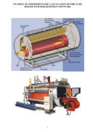
HEAT TRANSFER IN FIRE-TUBE BOILERS<br />
Doctoral dissertation<br />
Defended <strong>in</strong> December 2000 at<br />
University of Ljubljana, Slovenia, Department for Mechanical Eng<strong>in</strong>eer<strong>in</strong>g<br />
by<br />
Zeljko Warga, Slovenia<br />
Summary<br />
Mentor:<br />
Prof. Peter Novak, Slovenia<br />
Co-mentor:<br />
Prof. Wladimir L<strong>in</strong>zer, Institute for Thermal Eng<strong>in</strong>eer<strong>in</strong>g,<br />
Technical University Vienna, Austria<br />
A research of <strong>heat</strong> <strong>transfer</strong> <strong>in</strong> <strong>fire</strong>-<strong>tube</strong> <strong><strong>boiler</strong>s</strong> was conducted, a mathematical<br />
model for the <strong>heat</strong> <strong>transfer</strong> <strong>in</strong> the <strong>fire</strong>-<strong>tube</strong> <strong><strong>boiler</strong>s</strong> was developed, and a<br />
correspond<strong>in</strong>g computer software model was written. The model enables a more<br />
accurate analytical assessment of the impact of coiled-wire turbulence promoters<br />
on the <strong>heat</strong> <strong>transfer</strong> and pressure drop <strong>in</strong> <strong>boiler</strong> <strong>tube</strong>s, it allows for a more<br />
accurate determ<strong>in</strong>ation of the mean radiant temperature <strong>in</strong> <strong>boiler</strong> segments and<br />
takes <strong>in</strong> account the <strong>heat</strong> <strong>transfer</strong> from imp<strong>in</strong>g<strong>in</strong>g jet s<strong>in</strong>ce the latter was found to<br />
have a significant impact on <strong>heat</strong> <strong>transfer</strong> <strong>in</strong> <strong>fire</strong>-<strong>tube</strong> <strong><strong>boiler</strong>s</strong>. The model was<br />
verified on several test <strong><strong>boiler</strong>s</strong> of sizes rang<strong>in</strong>g from smaller residential hot water<br />
units to a larger <strong>in</strong>dustrial steam unit <strong>boiler</strong>. The comparison between the<br />
modeled values with those measured was very good.<br />
1
ACKNOWLEDGMENT<br />
The author thanks the follow<strong>in</strong>g who contributed <strong>in</strong> mak<strong>in</strong>g of this work:<br />
• Prof. Peter Novak, Department of Mechanical Eng<strong>in</strong>eer<strong>in</strong>g, University of<br />
Ljubljana, Slovenia;<br />
• Prof. Wladimir L<strong>in</strong>zer, Institute for Thermal Eng<strong>in</strong>eer<strong>in</strong>g, Technical University<br />
of Vienna, Austria;<br />
• Dr. V<strong>in</strong>cenc Butala, Prof. Joze Duhovnik, late Dr. Joze Zupancic and late Prof.<br />
H<strong>in</strong>ko Muren, Department of Mechanical Eng<strong>in</strong>eer<strong>in</strong>g, University of Ljubljana,<br />
Slovenia<br />
• Weishaupt GmbH, a corporation of Germany;<br />
• R.W. Beckett Corporation, Ohio, U.S.A.;<br />
• Dr. Thomas Butcher, Brookhaven National Laboratory, Energy Sciences and<br />
Technology Department, New York, U.S.A.;<br />
• Tucson Electric Power Company, a subsidiary of UniSource Energy<br />
Corporation, Tucson, Arizona, U.S.A.;<br />
• Tucson Medical Center, Tucson, Arizona, U.S.A.;<br />
• <strong>in</strong>oMETAL, a company of Slovenia;<br />
• C o m e t , a c o m p a n y o f S l o v e n i a ;<br />
• Burton E. Waite Jr., Phoenix, Arizona, U.S.A.;<br />
• Prof. Alex Dely, Tucson, Arizona, U.S.A.<br />
2
1. Foreword<br />
A general mathematical model for <strong>heat</strong> <strong>transfer</strong> calculations <strong>in</strong> <strong><strong>boiler</strong>s</strong> shall<br />
enable the follow<strong>in</strong>g:<br />
• Lessen the errors associated with determ<strong>in</strong><strong>in</strong>g the amount of <strong>heat</strong> <strong>transfer</strong> <strong>in</strong><br />
<strong><strong>boiler</strong>s</strong> descend<strong>in</strong>g from the use of actual mean flame temperatures;<br />
• Simplify the <strong>heat</strong> exchanger factor <strong>in</strong> cases of convection and simplification of<br />
the view factor determ<strong>in</strong>ation <strong>in</strong> case of radiation;<br />
• Determ<strong>in</strong>e an analytical method for the assessment of the impact of<br />
turbulators on the <strong>heat</strong> <strong>transfer</strong> and pressure drop;<br />
• Assess portions of the <strong>heat</strong> exchanged by convection and radiation <strong>in</strong> each<br />
<strong>boiler</strong> section;<br />
• Determ<strong>in</strong>e an accurate wall temperature.<br />
Simplifications are allowed for the follow<strong>in</strong>g cases:<br />
• Heat exchanger factor for convection;<br />
• View factor for radiation;<br />
• Wall temperature for convection on the water side.<br />
2. Def<strong>in</strong>ition of the problems<br />
2.1 Heat <strong>transfer</strong> by thermal radiation <strong>in</strong> <strong><strong>boiler</strong>s</strong><br />
To determ<strong>in</strong>e the radiant and convective part of <strong>heat</strong> <strong>transfer</strong> <strong>in</strong> the <strong>fire</strong>-<strong>tube</strong><br />
<strong><strong>boiler</strong>s</strong> the effective temperatures <strong>in</strong> each <strong>boiler</strong> section must be known. In case<br />
of convection that temperature is <strong>transfer</strong>red to mean logarithmic temperature<br />
difference. For the radiation from the hot flame and flue-gases to a cooled<br />
enclosure of simple geometry, which is the case with cyl<strong>in</strong>drical shape of the<br />
furnace <strong>in</strong> <strong>fire</strong>-<strong>tube</strong> <strong><strong>boiler</strong>s</strong>, the literature quotes an approximate approach to<br />
calculate the total radiant <strong>heat</strong> flow from hot flame and gas to the <strong>boiler</strong> walls by<br />
def<strong>in</strong><strong>in</strong>g an effective flame temperature. That approach is not based on the laws<br />
of physics, it was <strong>in</strong>troduced solely due to its simplicity compared to other<br />
methods for large water-cooled furnaces. However, it tends to be less accurate<br />
s<strong>in</strong>ce it cannot accurately asses a comb<strong>in</strong>ation of flame and gas radiation. A<br />
more accurate yet simple equation for mean radiant temperature (MRT) has not<br />
yet been published.<br />
2.2 Turbulators <strong>in</strong> <strong>boiler</strong> <strong>tube</strong>s<br />
Turbulence promoters (hereafter refereed to as turbulators) are <strong>in</strong>serts which<br />
<strong>in</strong>crease the rate of convection <strong>in</strong> the <strong>tube</strong>s compared to those which are empty.<br />
As their name implies, their function is to <strong>in</strong>crease the turbulence of the hot gases<br />
flow by break<strong>in</strong>g up the lam<strong>in</strong>ar boundary layer and thereby <strong>in</strong>creas<strong>in</strong>g<br />
convection. These devices appear <strong>in</strong> different shapes. Meanwhile, a more<br />
accurate <strong>heat</strong> <strong>transfer</strong> calculation <strong>in</strong> <strong><strong>boiler</strong>s</strong> calls for a more accurate analytical<br />
assessment of turbulators’ effect on the total <strong>heat</strong> <strong>transfer</strong>. This is of particular<br />
importance <strong>in</strong> order to appropriately operate the <strong>boiler</strong> system, <strong>in</strong>clud<strong>in</strong>g the<br />
burner. An <strong>in</strong>appropriate assessment of turbulators’ impact on pressure drop can<br />
3
cause the chok<strong>in</strong>g of the burner because its fan would be unable to overcome the<br />
<strong>in</strong>creased pressure drop <strong>in</strong> the <strong>boiler</strong> due to an <strong>in</strong>accurate assessment of the<br />
turbulators’ comb<strong>in</strong>ed effect on <strong>heat</strong> exchange and pressure drop.<br />
Coiled-wire turbulators are, today, the most widely used but this area has not yet<br />
been researched enough, and the available theory needs to be extended. The<br />
latest published results of experiments and theory is limited to coiled-wire<br />
turbulators with smaller diameters which is not applicable to <strong><strong>boiler</strong>s</strong> where the<br />
<strong>tube</strong>s are of larger diameter.<br />
2.3 Heat <strong>transfer</strong> by convection <strong>in</strong> <strong><strong>boiler</strong>s</strong><br />
Convection <strong>in</strong> <strong><strong>boiler</strong>s</strong> takes place simultaneously with radiation. In <strong>tube</strong>s of <strong>fire</strong><strong>tube</strong><br />
<strong><strong>boiler</strong>s</strong> more than 90% of <strong>heat</strong> exchange takes place by the convection. In<br />
the furnaces the radiant part is greater than <strong>in</strong> <strong>tube</strong>s. Calculation of convection is<br />
conducted by standard equations for flows <strong>in</strong> straight <strong>tube</strong>s and channels. This is<br />
also true for the <strong>boiler</strong> furnaces, whether they are circular or rectangular <strong>in</strong> crosssection.<br />
This picture totally changes when gas flow directly hits the surface<br />
<strong>in</strong>volved <strong>in</strong> convection, such as <strong>in</strong> the case of the rear of the furnace (Figure 1).<br />
The rate of convection is much higher <strong>in</strong> these cases and cannot be assessed by<br />
classical equations for straight flow <strong>in</strong> <strong>tube</strong>s and channels. Tests showed much<br />
lower gas exit temperatures from the furnace than had been calculated which<br />
was found to be attributable to lack<strong>in</strong>g of tak<strong>in</strong>g <strong>in</strong>to account the <strong>heat</strong> <strong>transfer</strong><br />
from imp<strong>in</strong>g<strong>in</strong>g jet of the flue-gases. This type of the <strong>heat</strong> <strong>transfer</strong> (Figure 2) had<br />
been <strong>in</strong>vestigated, but its role <strong>in</strong> <strong><strong>boiler</strong>s</strong> has not yet been <strong>in</strong>vestigated enough.<br />
Another special case of <strong>heat</strong> <strong>transfer</strong> <strong>in</strong> <strong><strong>boiler</strong>s</strong> is the use of a cyl<strong>in</strong>der of high<br />
temperature and corrosion resistant material <strong>in</strong> revers<strong>in</strong>g type furnaces. This<br />
cyl<strong>in</strong>der improves the long-term <strong>boiler</strong> performances (less scal<strong>in</strong>g of surfaces by<br />
unburned fuel sulfur, less soot), while also affect<strong>in</strong>g the radiation and convection<br />
(Figure 3). Further, tests show an overall improvement <strong>in</strong> <strong>heat</strong> <strong>transfer</strong> <strong>in</strong> <strong>boiler</strong><br />
with such a cyl<strong>in</strong>der. However, the theoretical background of cyl<strong>in</strong>der’s impact on<br />
local <strong>heat</strong> exchange has not yet been researched enough.<br />
4
cooled door <strong>in</strong>side wallarea<br />
of <strong>heat</strong> <strong>transfer</strong><br />
from imp<strong>in</strong>g<strong>in</strong>g jet<br />
circular<br />
furnace<br />
flue-gases path<br />
<strong>in</strong> <strong>boiler</strong><br />
<strong>tube</strong>s<br />
water<br />
furnace rear wall -<br />
area of <strong>heat</strong> <strong>transfer</strong><br />
from imp<strong>in</strong>g<strong>in</strong>g jet<br />
Figure 1: Areas of <strong>heat</strong> <strong>transfer</strong> from imp<strong>in</strong>g<strong>in</strong>g jet <strong>in</strong> <strong>fire</strong>-<strong>tube</strong> <strong><strong>boiler</strong>s</strong><br />
wall<br />
wall-jet region<br />
jet<br />
Z<br />
D<br />
d<br />
nozzle<br />
transition region<br />
region of fully developed jet flow<br />
stagnation po<strong>in</strong>t<br />
stagnation or<br />
imp<strong>in</strong>gement region<br />
Figure 2: Imp<strong>in</strong>g<strong>in</strong>g round jet to flat plate<br />
5
door area<br />
<strong>in</strong>side cyl<strong>in</strong>der:<br />
- area of no<br />
convection<br />
even when door<br />
is cooled<br />
- area of<br />
<strong>in</strong>creased MRT<br />
door area<br />
outside cyl<strong>in</strong>der:<br />
- area of <strong>in</strong>creased<br />
convection by<br />
<strong>in</strong>creased flue-gas<br />
velocity from r<strong>in</strong>g-slot<br />
(when door is cooled)<br />
- area of reduced MRT<br />
furnace wall<br />
<strong>in</strong>side cyl<strong>in</strong>der:<br />
- area of no convection<br />
- area of reduced radiation<br />
- area of <strong>in</strong>creased MRT<br />
cyl<strong>in</strong>der of high temp.<br />
resistant material<br />
<strong>in</strong> furnace<br />
part of furnace between<br />
cyl<strong>in</strong>der's end and rear wall<br />
- area of <strong>in</strong>creased MRT<br />
and <strong>in</strong>creased convection<br />
r<strong>in</strong>g-slot outside<br />
cyl<strong>in</strong>der and<br />
furnace walls:<br />
- area of <strong>in</strong>creased<br />
convection to furnace<br />
- area of radiation to furnace<br />
and cyl<strong>in</strong>der at reduced MRT<br />
furnace rear wall:<br />
- area of <strong>in</strong>creased<br />
convection due to<br />
<strong>in</strong>creased flue-gas<br />
velocity from cyl<strong>in</strong>der<br />
- area of <strong>in</strong>creased MRT<br />
Figure 3: Heat exchange <strong>in</strong> furnace of <strong>boiler</strong> with cyl<strong>in</strong>der of high temperature resistant material<br />
6
3. The experiments<br />
The tests were performed on actual residential-sized hot water <strong><strong>boiler</strong>s</strong> of 450 kW<br />
and steam <strong>boiler</strong> 4MW 10 bar by the direct method. These <strong><strong>boiler</strong>s</strong> were built <strong>in</strong> a<br />
two-pass with revers<strong>in</strong>g furnace design (Figure 1, Figure 5).<br />
3.1 The experimental program<br />
The research program consisted of the follow<strong>in</strong>g:<br />
1. Research of the <strong>heat</strong> <strong>transfer</strong> on conventional residential-sized hot water<br />
<strong><strong>boiler</strong>s</strong> with these configurations:<br />
• empty furnace and empty <strong>tube</strong>s;<br />
• cyl<strong>in</strong>der of high temperature resistant material <strong>in</strong> the furnace;<br />
• coiled-wire turbulators of vary<strong>in</strong>g geometry <strong>in</strong> <strong>tube</strong>s of vary<strong>in</strong>g diameters.<br />
2. Research of the pressure drop on conventional residential-sized hot water<br />
<strong><strong>boiler</strong>s</strong> with these configurations:<br />
• empty furnace and empty <strong>tube</strong>s;<br />
• cyl<strong>in</strong>der of high temperature resistant material <strong>in</strong> the furnace;<br />
• coiled-wire turbulators of vary<strong>in</strong>g geometry <strong>in</strong> <strong>tube</strong>s of vary<strong>in</strong>g diameters.<br />
3. Research of the <strong>heat</strong> <strong>transfer</strong> and pressure drop on conventional residentialsized<br />
hot water <strong><strong>boiler</strong>s</strong> of vary<strong>in</strong>g <strong>in</strong>ternal geometry with these configurations:<br />
• hot water <strong>boiler</strong> <strong>in</strong> conventional design;<br />
• above <strong>boiler</strong> with added cyl<strong>in</strong>der of high temperature resistant material <strong>in</strong><br />
the furnace <strong>in</strong> conventional <strong>boiler</strong> design;<br />
• above <strong>boiler</strong> with added cooled door;<br />
• above <strong>boiler</strong> with added short cooled-cyl<strong>in</strong>der on <strong>in</strong>side side of cooled<br />
door.<br />
4. Research of <strong>heat</strong> <strong>transfer</strong> on <strong>in</strong>dustrial size steam <strong>boiler</strong> with cyl<strong>in</strong>der of high<br />
temperature resistant material <strong>in</strong> the furnace and cooled door.<br />
7
4. Summary of test results<br />
Mean radiant temperature<br />
The <strong>in</strong>troduced approximation for MRT delivers an improved accuracy <strong>in</strong> <strong>heat</strong><br />
<strong>transfer</strong> calculations <strong>in</strong> <strong>fire</strong>-<strong>tube</strong> <strong><strong>boiler</strong>s</strong>. As is evident from the table below, while<br />
hold<strong>in</strong>g all other parameters constant, the <strong>in</strong>troduced equation for MRT delivers a<br />
higher radiation which results <strong>in</strong> a better agreement between the predicted and<br />
measured values of <strong>heat</strong> <strong>transfer</strong> <strong>in</strong> test <strong>fire</strong>-<strong>tube</strong> <strong><strong>boiler</strong>s</strong>.<br />
MRT by<br />
existent<br />
equation<br />
°C/K<br />
MRT by<br />
<strong>in</strong>troduced<br />
equation<br />
°C/K<br />
difference <strong>in</strong><br />
MRT<br />
%<br />
difference<br />
<strong>in</strong> calculated<br />
radiation<br />
%<br />
calculated/<br />
measured<br />
furnace exit<br />
temp. with<br />
MRT by<br />
existent<br />
equation<br />
°C<br />
calculated/<br />
measured<br />
furnace exit<br />
temp. with MRT<br />
by <strong>in</strong>troduced<br />
equation<br />
°C<br />
1251/1524 1477/1750 +18/+14.8 +43.7 727/609 630/609<br />
Coiled-wire turbulators <strong>in</strong> <strong>boiler</strong> <strong>tube</strong>s<br />
The analytical assessment of the impact of the coiled-wire turbulators on <strong>heat</strong><br />
<strong>transfer</strong> and pressure drop <strong>in</strong> straight <strong>tube</strong>s, enables a higher degree of accuracy<br />
as is evident from tables below.<br />
measured <strong>boiler</strong> <strong>heat</strong><br />
output<br />
kW<br />
calculated <strong>boiler</strong> <strong>heat</strong><br />
output<br />
kW<br />
absolute difference between<br />
measured and calculated <strong>heat</strong><br />
<strong>transfer</strong> <strong>in</strong> <strong>boiler</strong><br />
%<br />
446.7 442.2 -1<br />
measured gas side<br />
pressure drop <strong>in</strong> <strong>boiler</strong><br />
Pa<br />
calculated gas side<br />
pressure drop <strong>in</strong><br />
<strong>boiler</strong><br />
Pa<br />
absolute difference between<br />
measured and calculated<br />
pressure drop<br />
%<br />
97 88 -9.2<br />
The optimum dimensions of the coiled-wire turbulators to assure the maximum<br />
accuracy <strong>in</strong> calculations was found as shown <strong>in</strong> Figure 4. Additionally it was<br />
found that pitch, wire, and turbulator diameter do not significantly affect the<br />
accuracy of <strong>heat</strong> <strong>transfer</strong> calculations with the exception of an extremely low<br />
pitch. The turbulator length was found to be of importance and correspond<strong>in</strong>g<br />
coefficients tak<strong>in</strong>g the length of turbulator <strong>in</strong>to account were found.<br />
8
D<br />
m<strong>in</strong>. 0.8 D<br />
m<strong>in</strong>. 1/3 L<br />
L<br />
max. 0.5 mm<br />
Figure 4: Optimum dimensions of coiled-wire turbulator to assure +10-15% accuracy <strong>in</strong> pressure<br />
drop estimation<br />
Role of <strong>heat</strong> <strong>transfer</strong> from imp<strong>in</strong>g<strong>in</strong>g jet <strong>in</strong> <strong><strong>boiler</strong>s</strong><br />
Research on test <strong><strong>boiler</strong>s</strong> showed the role of <strong>heat</strong> <strong>transfer</strong> from imp<strong>in</strong>g<strong>in</strong>g jet is<br />
highly significant <strong>in</strong> the analytical assessment of <strong>heat</strong> exchange <strong>in</strong> the furnace.<br />
As is evident from the table below, the <strong>heat</strong> <strong>transfer</strong> from imp<strong>in</strong>g<strong>in</strong>g jet can<br />
contribute to more than 80% of all convection <strong>in</strong> the furnace. Temperatures of<br />
surfaces exposed to <strong>heat</strong> <strong>transfer</strong> from imp<strong>in</strong>g<strong>in</strong>g jet are more than 100% higher<br />
than those of surfaces not <strong>in</strong>volved <strong>in</strong> <strong>heat</strong> <strong>transfer</strong> from imp<strong>in</strong>g<strong>in</strong>g jet..<br />
convective<br />
<strong>heat</strong> <strong>transfer</strong><br />
coefficient<br />
W/m 2 K<br />
convective <strong>heat</strong><br />
<strong>transfer</strong><br />
coefficient<br />
from jet<br />
imp<strong>in</strong>gement<br />
W/m 2 K<br />
convection<br />
from jet<br />
imp<strong>in</strong>gement<br />
kW<br />
total<br />
convection<br />
kW<br />
convection<br />
from jet<br />
imp<strong>in</strong>gement vs.<br />
total convection<br />
%<br />
11.7 165.2 150.4 183 82.1<br />
9
5. Conclusion<br />
In conventional 3- and 4-pass <strong>fire</strong>-<strong>tube</strong> <strong><strong>boiler</strong>s</strong>, only a smaller portion of total <strong>heat</strong><br />
is <strong>transfer</strong>red <strong>in</strong> the furnace as it has as much as 90% and more <strong>heat</strong> <strong>transfer</strong><br />
surfaces <strong>in</strong> the <strong>tube</strong>s. The radiation <strong>in</strong> the <strong>tube</strong>s is almost nonexistent compared<br />
to convection, while <strong>in</strong> the furnace, the radiation can be even smaller than<br />
convection, as the test <strong><strong>boiler</strong>s</strong> demonstrated. This is <strong>in</strong> total contradiction to<br />
water-<strong>tube</strong> <strong><strong>boiler</strong>s</strong> where convection represents less than 20% of total amount of<br />
<strong>heat</strong> exchange <strong>in</strong> furnace. As the test <strong><strong>boiler</strong>s</strong> demonstrated, the total <strong>heat</strong><br />
exchange <strong>in</strong> the furnace can be as high as 80%. Hot water test <strong><strong>boiler</strong>s</strong> showed<br />
additionally that the percentage of surfaces <strong>in</strong> <strong>tube</strong>s could be close to that found<br />
<strong>in</strong> the furnace. The <strong>in</strong>dustrial-sized steam test <strong>boiler</strong> has as low as 2.3 times<br />
more area <strong>in</strong> the <strong>tube</strong>s then <strong>in</strong> the rest of the <strong>boiler</strong>. Furthermore it was proved<br />
that the convection <strong>in</strong> the furnace of <strong>fire</strong>-<strong>tube</strong> <strong><strong>boiler</strong>s</strong> can be made even higher<br />
than the radiation.<br />
The number of <strong>boiler</strong> <strong>tube</strong>s is limited by burner fan capability to overcome<br />
<strong>in</strong>ternal pressure loss. By that fact, the general direction <strong>in</strong> design<strong>in</strong>g <strong>fire</strong>-<strong>tube</strong><br />
<strong><strong>boiler</strong>s</strong> is given; namely to <strong>in</strong>stall only as many <strong>tube</strong>s as are necessary. This<br />
requires the exact analytical assessment of <strong>heat</strong> <strong>transfer</strong> <strong>in</strong> particular <strong>boiler</strong><br />
sections to which this dissertation was devoted. Thus, by proper design of the<br />
<strong>boiler</strong> (for which the <strong>in</strong>-deep knowledge of <strong>heat</strong> <strong>transfer</strong> is of primary importance),<br />
as demonstrated <strong>in</strong> this dissertation, a sizable <strong>in</strong>tensification of <strong>heat</strong> <strong>transfer</strong> and<br />
noticeable sav<strong>in</strong>gs <strong>in</strong> <strong>boiler</strong> manufactur<strong>in</strong>g cost can be achieved.<br />
Three units of the test <strong><strong>boiler</strong>s</strong>, designed under the consideration of the new<br />
f<strong>in</strong>d<strong>in</strong>gs described <strong>in</strong> this dissertation (steam <strong>boiler</strong> of 4MW 10bar) were built and<br />
delivered to actual customer <strong>in</strong> USA <strong>in</strong> 2001 (www.<strong>warga</strong><strong>boiler</strong>.com). Compared<br />
with conventional design the noticeable improvements are evident as f.i. the<br />
number of <strong>boiler</strong> <strong>tube</strong>s which is reduced for more than 70%.<br />
Figure 5: Steam test <strong><strong>boiler</strong>s</strong> <strong>in</strong> actual operation<br />
10
1. APPARATUS AND EXPERIMENTAL UNCERTAINTY USED FOR TESTING<br />
OF TEST BOILERS<br />
The assessment of accuracy of the test<strong>in</strong>g l<strong>in</strong>e for <strong>boiler</strong> thermal output and<br />
efficiency was performed accord<strong>in</strong>g to Policy on Report<strong>in</strong>g Uncerta<strong>in</strong>ties <strong>in</strong><br />
Experimental Measurements and Results.<br />
1.1 The apparatus used for test<strong>in</strong>g of hot water test <strong><strong>boiler</strong>s</strong><br />
The hot water <strong>boiler</strong> test<strong>in</strong>g l<strong>in</strong>e was built accord<strong>in</strong>g to German Standard DIN<br />
4702, Teil 2. The tests on the <strong><strong>boiler</strong>s</strong> were run under the same conditions (steady<br />
state, 30-m<strong>in</strong>ute m<strong>in</strong>imum test duration etc.). The average difference between<br />
<strong>boiler</strong> thermal output calculated from repeated tests under the same conditions<br />
was less than ±0.5%.<br />
Data acquisition:<br />
Hewlett Packard® 9000/226 digital data acquisition system:<br />
• digital scanner HP 3497 A<br />
• digital voltmeter HP 3456 A<br />
• l<strong>in</strong>e pr<strong>in</strong>ter HP 2631 A<br />
• computer 9000/300<br />
Temperatures:<br />
• thermocouples NiCr - Ni B 1475, PT 100 by Degussa®, Italy<br />
Flow rates:<br />
• natural gas flow: gas flow meter G65 DN80 by Rombach®m, Germany<br />
• water rates: analog scale of 0-1000 kg range, KG II by Libela-Celje®, Slovenia<br />
• oil rates: analog scale of 0-50 kg range, KG II by Libela-Celje®, Slovenia<br />
Time <strong>in</strong>tervals:<br />
• stop-watch of 0-60s and 0-30 m<strong>in</strong>. range by Zaquet®, Germany<br />
Flue-gases analysis:<br />
• electrochemical analyzer Combilyzer 2000 by Afriso®, Germany<br />
Boiler <strong>in</strong>ternal flue-gases side pressure drop:<br />
• U-<strong>tube</strong> differential pressure gauge with liquid<br />
Flue draft:<br />
• <strong>tube</strong> micro manometer with liquid<br />
Fuel <strong>heat</strong><strong>in</strong>g value:<br />
• oil: calorimeter C-4000 by Ika-Werk®, Germany<br />
• natural gas: calculated accord<strong>in</strong>g to chemical analysis (97.3% Methane CH4)<br />
1
1.2 Assessment of measurement uncerta<strong>in</strong>ty for hot water test <strong>boiler</strong><br />
• temperatures <strong>in</strong> 22.1-81.0°C range (calibration results):<br />
at t1=22.1°C: -0.32°C (-1.44%)<br />
at t2=81.0°C:-0.47°C (-0.58%)<br />
• water rate (calibration results): -0.5%<br />
• liquid fuel rate (calibration results): -0.025%<br />
• gaseous fuel rate (calibration results):<br />
m<strong>in</strong>. rate: -0.29%<br />
max. rate: -0.39%<br />
average: -0.34%<br />
• liquid fuel <strong>heat</strong><strong>in</strong>g value: -1.5% (calibration results)<br />
• natural gas (>97% CH4) <strong>heat</strong><strong>in</strong>g value: calculated as 100% methane<br />
• CO - emission: ±10% of displayed value<br />
• rest oxygen: ±8% of displayed value<br />
• NOx - emission: ±10% of displayed value<br />
• differential pressure and <strong>boiler</strong> draft: ±0.5 mmH2O (±5 Pa)<br />
Maximum expected uncerta<strong>in</strong>ty <strong>in</strong> calculat<strong>in</strong>g the <strong>boiler</strong> thermal <strong>in</strong>put:<br />
Qfuel = B ⋅ Hi<br />
[W]<br />
• PQ/Q=0.005 (from average tests results)<br />
• BB/B=0.0034 (from calibration)<br />
• BH/H=0.015 (from calibration)<br />
U<br />
Q<br />
Q<br />
fuel<br />
=<br />
⎛<br />
⎜<br />
⎝ Q<br />
2<br />
2<br />
B ⎞ Q ⎛ BB<br />
⎞ ⎛ BH<br />
fuel<br />
⎛ P<br />
⎜<br />
⎝ Q<br />
Q<br />
fuel<br />
⎟<br />
⎠<br />
⎞<br />
⎟<br />
⎠<br />
2<br />
=<br />
=<br />
⎜<br />
⎝<br />
B<br />
⎛ B<br />
+ ⎜<br />
⎝ Q<br />
⎟<br />
⎠<br />
0.<br />
0034<br />
Q<br />
fuel<br />
+ ⎜<br />
⎝ H<br />
⎞<br />
⎟<br />
⎠<br />
2<br />
2<br />
2<br />
⎞<br />
⎟<br />
⎠<br />
+ 0.<br />
015<br />
=<br />
2<br />
0.<br />
005<br />
2<br />
=<br />
0.<br />
0153<br />
+ 0.<br />
0153<br />
=<br />
2<br />
1.<br />
53%<br />
=<br />
0.<br />
016<br />
= 1.<br />
6%<br />
Maximum expected uncerta<strong>in</strong>ty <strong>in</strong> calculat<strong>in</strong>g the <strong>boiler</strong> thermal output:<br />
Q<br />
.<br />
= mH<br />
O ⋅ c ⋅ ( t − t ) [W]<br />
<strong>boiler</strong><br />
2<br />
p<br />
H 2O,<br />
2 H 2O,<br />
1<br />
• ∆t=65±5°C (average tests results)<br />
• PQ/Q=0.005 (from average tests results)<br />
• B’t1=
⎛ B<br />
⎜<br />
⎝ Q<br />
Q<br />
<strong>boiler</strong><br />
2 2 2<br />
⎞ Bm<br />
Bc<br />
Bt<br />
Bt<br />
Bt<br />
Bt<br />
⎟ =<br />
⎠ m c t t t t<br />
⎛ ⎞<br />
⎜ ⎟ +<br />
⎝ ⎠<br />
⎛ ⎞<br />
⎜ ⎟ +<br />
⎝ ⎠<br />
⎛ ⎞<br />
⎜ ⎟ +<br />
⎝ ⎠<br />
⎛ ⎞<br />
⎜ ⎟ −<br />
⎝ ⎠<br />
⎛ ⎞<br />
⎜ ⎟ ⋅<br />
⎝ ⎠<br />
⎛<br />
' '<br />
⎞<br />
1<br />
2<br />
1 2<br />
2 ⎜ ⎟<br />
∆ ∆ ∆ ⎝ ∆ ⎠<br />
Q<br />
U<br />
( ) ( ) ( ) ( )<br />
= 0. 005 + 0. 005 + 0. 32 / 65 + 0. 47 / 65 − 2 ⋅ 0. 05 / 65 ⋅ 0. 05 / 65<br />
= 0. 0112 = 112% .<br />
Q<br />
<strong>boiler</strong><br />
=<br />
⎛ P<br />
⎜<br />
⎝ Q<br />
2<br />
2 2 2 2<br />
Q<br />
<strong>boiler</strong><br />
⎞<br />
⎟<br />
⎠<br />
2<br />
⎛ B<br />
+ ⎜<br />
⎝ Q<br />
Q<br />
<strong>boiler</strong><br />
⎞<br />
⎟<br />
⎠<br />
2<br />
=<br />
2<br />
0.<br />
005<br />
2<br />
+ 0.<br />
0112<br />
2<br />
=<br />
0.<br />
0122<br />
Maximum expected uncerta<strong>in</strong>ty <strong>in</strong> calculat<strong>in</strong>g the <strong>boiler</strong> efficiency:<br />
Q<strong>boiler</strong><br />
η<strong>boiler</strong> = ⋅100 [%]<br />
Q<br />
Uη<br />
=<br />
η<br />
⎛ U<br />
⎜<br />
⎝ Q<br />
Q<br />
<strong>boiler</strong><br />
⎞<br />
⎟<br />
⎠<br />
2<br />
⎛ U<br />
+ ⎜<br />
⎝ Q<br />
Q<br />
fuel<br />
⎞<br />
⎟<br />
⎠<br />
2<br />
=<br />
fuel<br />
0.<br />
0122<br />
2<br />
+ 0.<br />
016<br />
1.3 The apparatus used for test<strong>in</strong>g of steam test <strong>boiler</strong><br />
2<br />
=<br />
0.<br />
0201<br />
=<br />
= 1.<br />
22<br />
2.<br />
01%<br />
The tests on the steam <strong>boiler</strong> were run <strong>in</strong> an actual <strong>boiler</strong> room for steam <strong>heat</strong><strong>in</strong>g<br />
(see Figure 5) <strong>in</strong> steady state, with a m<strong>in</strong>imum duration of 30 m<strong>in</strong>utes. The<br />
average difference between the <strong>boiler</strong> thermal output calculated from the tests<br />
was less than ±0.5%.<br />
Omega® DAQ-12 data acquisition system:<br />
• DAQP-12A term<strong>in</strong>al strip<br />
• PCMCIA card UIO-37 with 12 bit 8/16 channel analog <strong>in</strong>put<br />
• CP-DAQP cable<br />
• OMX-R250, 250 ohm precision resistors<br />
• Portable computer Toshiba® Satellite 310 series<br />
Steam & gas flow rates and temperatures of media (steam, gas, feed water):<br />
• Rosemount & Fisher® 3095 M multivariable mass flow orifice type transmitter<br />
with remote feed water temperature pt 100 sensor<br />
Flue-gases analysis:<br />
• EGA Sampl<strong>in</strong>g system by Autoflame® (came as part of burner equipment)<br />
Boiler <strong>in</strong>ternal flue-gases side pressure drop:<br />
• U-<strong>tube</strong> differential pressure gauge with liquid<br />
Flue draft:<br />
• <strong>tube</strong> micro manometer with liquid<br />
Fuel <strong>heat</strong><strong>in</strong>g value:<br />
• natural gas: calculated accord<strong>in</strong>g to chemical analysis (97.3% Methane CH4)<br />
3
1.4 Assessment of measurement uncerta<strong>in</strong>ty for steam test <strong>boiler</strong><br />
• temperatures (calibration results): at t=81.0°C: -0.47°C (-0.58%)<br />
• steam and gas rate (calibration results): +/-0.8% (average)<br />
• natural gas (>97% CH4) <strong>heat</strong><strong>in</strong>g value: calculated as 100% methane<br />
• differential pressure and <strong>boiler</strong> draft: ±0.5 mmH2O (±5 Pa)<br />
Maximum expected uncerta<strong>in</strong>ty <strong>in</strong> calculat<strong>in</strong>g the <strong>boiler</strong> thermal <strong>in</strong>put:<br />
Qfuel = B ⋅ Hi<br />
[W]<br />
• PQ/Q=0.005 (from average tests results)<br />
• BB/B=0.01 (from calibration)<br />
• BH/H=0.01 (from calibration)<br />
U<br />
Q<br />
Q<br />
fuel<br />
=<br />
⎛ P<br />
⎜<br />
⎝ Q<br />
⎛<br />
⎜<br />
⎝ Q<br />
Q<br />
fuel<br />
2<br />
2<br />
B ⎞ Q ⎛ BB<br />
⎞ ⎛ BH<br />
fuel<br />
2<br />
⎟ ⎞<br />
⎠<br />
⎟<br />
⎠<br />
=<br />
=<br />
⎜<br />
⎝<br />
⎛ B<br />
+ ⎜<br />
⎝ Q<br />
Q<br />
fuel<br />
B<br />
⎟<br />
⎠<br />
+ ⎜<br />
⎝ H<br />
2 2<br />
0.<br />
01 + 0.<br />
01 =<br />
⎞<br />
⎟<br />
⎠<br />
2<br />
=<br />
2<br />
⎞<br />
⎟<br />
⎠<br />
0.<br />
005<br />
2<br />
0.<br />
014<br />
+ 0.<br />
014<br />
= 1.<br />
4%<br />
2<br />
=<br />
0.<br />
0148<br />
= 1.<br />
48%<br />
The maximum expected uncerta<strong>in</strong>ty <strong>in</strong> calculat<strong>in</strong>g the <strong>boiler</strong> thermal output<br />
accord<strong>in</strong>g to the manufacturer of the steam flow measurement equipment:<br />
Q = V steam ⋅ ( h − h )<br />
.<br />
[W]<br />
Q<br />
U<br />
Q<br />
<strong>boiler</strong><br />
=<br />
⎛ P<br />
⎜<br />
⎝ Q<br />
Q<br />
<strong>boiler</strong><br />
⎞<br />
⎟<br />
⎠<br />
2<br />
<strong>boiler</strong><br />
⎛ B<br />
+ ⎜<br />
⎝ Q<br />
⎛ B<br />
⎜<br />
⎝ Q<br />
Q<br />
<strong>boiler</strong><br />
Q<br />
<strong>boiler</strong><br />
⎞<br />
⎟<br />
⎠<br />
2<br />
=<br />
⎞<br />
⎟<br />
⎠<br />
steam<br />
2<br />
= 1%<br />
0.<br />
005<br />
2<br />
fw<br />
+ 0.<br />
01<br />
2<br />
=<br />
0.<br />
0111<br />
=<br />
1.<br />
11%<br />
Maximum expected uncerta<strong>in</strong>ty <strong>in</strong> calculat<strong>in</strong>g the steam <strong>boiler</strong> efficiency:<br />
Q<strong>boiler</strong><br />
η<strong>boiler</strong> = ⋅100 [%]<br />
Q<br />
Uη<br />
=<br />
η<br />
⎛ U<br />
⎜<br />
⎝ Q<br />
Q<br />
<strong>boiler</strong><br />
⎞<br />
⎟<br />
⎠<br />
2<br />
⎛ U<br />
+ ⎜<br />
⎝ Q<br />
Q<br />
fuel<br />
2<br />
⎟ ⎞<br />
⎠<br />
=<br />
fuel<br />
2<br />
2<br />
0.<br />
0111 + 0.<br />
0148 =<br />
0.<br />
0185<br />
= 1.<br />
85%<br />
4
2. THE EXPERIMENTS<br />
Introduction<br />
The tests were performed on actual residential-sized hot water <strong><strong>boiler</strong>s</strong> based on<br />
standardized <strong>boiler</strong> test<strong>in</strong>g l<strong>in</strong>e and arrangements accord<strong>in</strong>g to German standard<br />
DIN 4702 Part 2 by the direct method. The f<strong>in</strong>al tests were performed on<br />
<strong>in</strong>dustrial sized steam <strong>boiler</strong> <strong>in</strong> <strong>boiler</strong> room, with the results be<strong>in</strong>g evaluated per<br />
above standard.<br />
2.1 Description of hot water <strong>boiler</strong> test<strong>in</strong>g l<strong>in</strong>e<br />
Figure 1 shows a test<strong>in</strong>g l<strong>in</strong>e for measur<strong>in</strong>g the hot water <strong>boiler</strong> output and<br />
efficiency by direct method. Figure 2 depicts the test<strong>in</strong>g l<strong>in</strong>e for measur<strong>in</strong>g the<br />
<strong>boiler</strong>’s <strong>in</strong>ternal pressure drop on the flue-gases side. Figure 3 shows the<br />
arrangement for fuel flow measur<strong>in</strong>g. Section 1 lists the apparatus used and<br />
provides an estimation of measurement uncerta<strong>in</strong>ty.<br />
outflow<br />
<strong>boiler</strong> water<br />
barrel<br />
tv<br />
constant<br />
level<br />
barrel deaeration<br />
scale<br />
<strong>boiler</strong><br />
RV2<br />
constant level<br />
supply water barrel<br />
te<br />
P<br />
RV1<br />
tr<br />
constant<br />
water<br />
pressure<br />
valve<br />
RV<br />
fresh<br />
water<br />
supply<br />
Figure 1: Test<strong>in</strong>g l<strong>in</strong>e for <strong>heat</strong> output and efficiency of hot water <strong><strong>boiler</strong>s</strong><br />
All pipes conta<strong>in</strong><strong>in</strong>g the <strong>boiler</strong> water are thermally <strong>in</strong>sulated and their <strong>heat</strong> losses<br />
are known. The pump (P) pushes the water through the <strong>boiler</strong>. The fresh water<br />
first reaches the water barrel and ma<strong>in</strong>ta<strong>in</strong>s a constant level, which is located<br />
usually at the attic. The desired fresh water flow <strong>in</strong>to barrel is adjusted by valve<br />
(RV) and then ma<strong>in</strong>ta<strong>in</strong>ed by valve (RV1). Before the fresh water with<br />
temperature, tE, enters the <strong>boiler</strong>, it is premixed with <strong>boiler</strong> water of temperature,<br />
tV, by valve (RV2), which adjusts the premix<strong>in</strong>g rate and temperature difference<br />
5
(tV-tR). The premixed water then enters the <strong>boiler</strong> with the temperature, tR. The<br />
same quantity of water that enters the <strong>boiler</strong> also leaves it. Boiler water exit<strong>in</strong>g the<br />
<strong>boiler</strong> and fuel flow are weighted separately by scales.<br />
The water temperatures are measured by thermocouples, as is the ambient<br />
temperature. The flue-gases temperatures <strong>in</strong> the test <strong>boiler</strong> were measured by<br />
protected thermocouples at follow<strong>in</strong>g po<strong>in</strong>ts:<br />
• furnace exit <strong>in</strong> leftmost, rightmost, uppermost and lowermost <strong>tube</strong>;<br />
• <strong>boiler</strong> exit.<br />
As shown on Figure 2, the test<strong>in</strong>g l<strong>in</strong>e arrangement for measur<strong>in</strong>g the <strong>in</strong>ternal<br />
flue-gases pressure drop <strong>in</strong> the <strong>boiler</strong> is simple and consists of only one l<strong>in</strong>e. One<br />
end penetrates the flue-gases exit from <strong>boiler</strong>, while the other end is <strong>in</strong> the<br />
furnace. The color-liquid filled gauge on the top (where all l<strong>in</strong>e-ends meet) shows<br />
the differential pressure, ∆p, <strong>in</strong> mm of water column, thereby represent<strong>in</strong>g the<br />
<strong>in</strong>ternal pressure drop <strong>in</strong> <strong>boiler</strong>.<br />
from furnace<br />
<strong>boiler</strong><br />
flue<br />
Figure 2: Test<strong>in</strong>g l<strong>in</strong>e for pressure drop <strong>in</strong> <strong>boiler</strong><br />
liquid fuel<br />
barrel<br />
scale<br />
h<br />
<strong>boiler</strong><br />
Figure 3: Liquid fuel flow measur<strong>in</strong>g arrangement<br />
6
2.2 Description of steam <strong>boiler</strong> test<strong>in</strong>g l<strong>in</strong>e<br />
The tests on the steam <strong><strong>boiler</strong>s</strong> were performed dur<strong>in</strong>g the actual operation as<br />
depicted <strong>in</strong> Figure 5 by the direct method. Fresh water comes to chemical water<br />
treatment (4) from where it goes to the <strong>boiler</strong> feed water tank (3) with deaerator<br />
where it gets pre-warmed and deoxidized afterwards it enters <strong>boiler</strong> (1) via the<br />
feed water pump. The additional feed water tank (5) serves the purpose of stor<strong>in</strong>g<br />
the extra feed water to cover the demand at peak loads.<br />
The fuel, natural gas, is delivered to burner (2) through gas tra<strong>in</strong> (8) accord<strong>in</strong>g to<br />
ASME Boiler and pressure vessel code CSC-1. The valves are controlled by<br />
Honeywell®, model 7800, electronics located <strong>in</strong> the burner command box. Boiler<br />
(1) is equipped with two sets of water gages, McDonnell&Miller® and<br />
Honeywell®. The <strong>boiler</strong> feed pump is controlled by a McDonnell&Miller® water<br />
level gage. In the <strong>boiler</strong> flue, the Exhaust Gas Analysis (EGA) electrode for O2,<br />
CO2, CO, NOx and temperature probes are located transmitt<strong>in</strong>g signals to an<br />
Autoflame® unit located <strong>in</strong> the burner control box, display<strong>in</strong>g and calculat<strong>in</strong>g the<br />
combustion efficiency. On the basis of a comparison between the measured and<br />
pre-set values, this unit controls the servomotors for air and fuel delivery to the<br />
burner.<br />
The generated steam <strong>in</strong> the <strong>boiler</strong> comes to the steam distribut<strong>in</strong>g and steam<br />
pressure reduc<strong>in</strong>g valve (7) direct<strong>in</strong>g a necessary part of it to steam <strong>heat</strong><strong>in</strong>g<br />
system, the rest to the atmosphere. The condensate from the <strong>heat</strong><strong>in</strong>g system<br />
then goes to condensate tank (6). The amount of steam generated and the<br />
<strong>in</strong>com<strong>in</strong>g gas are measured by flow multivariable orifice type transmitters placed<br />
<strong>in</strong> steam l<strong>in</strong>e (10) and gas tra<strong>in</strong>, respectively. The feed water temperature is<br />
measured by a thermocouple located <strong>in</strong> the feed water-deliver<strong>in</strong>g pipe. The test<br />
data are acquired via portable computer and data acquisition system (see Figure<br />
4), convert<strong>in</strong>g 4-20mA current com<strong>in</strong>g from flow transmitters to 1-5V of electric<br />
force via resistors (see section 1) for list of apparatus and estimation of<br />
measurement uncerta<strong>in</strong>ty). The eng<strong>in</strong>eer<strong>in</strong>g values are then calculated from<br />
voltage, written to the file and used to calculate <strong>boiler</strong> <strong>in</strong>put, output, and<br />
efficiency.<br />
Figure 4: Data acquisition system<br />
7
5<br />
water level gage<br />
feed water<br />
6<br />
condensate<br />
M M<br />
4<br />
water<br />
level<br />
gage<br />
pressure gage<br />
pressure gage<br />
feed water<br />
pressure<br />
gage<br />
Y<br />
thermometer<br />
Y<br />
Y<br />
Y<br />
deaerator<br />
PC<br />
LEGEND<br />
PC<br />
pressure control<br />
3<br />
pressure gage<br />
30 X D<br />
9<br />
to computer<br />
p, p, t<br />
p<br />
temp. control<br />
TC<br />
7 X D<br />
p t<br />
D<br />
p<br />
Z<br />
Z<br />
AUTOFLAME<br />
8<br />
feed water<br />
2<br />
switch for<br />
p pressure<br />
gage<br />
natural gas<br />
l<strong>in</strong>e<br />
EGA - exhaust gas analysis<br />
1 steam <strong>boiler</strong> 4MW 10bar, 6t/h steam<br />
2 dual fue burner Weishaupt RGL 60 2-A with Autoflame combustion control for O2, CO2, CO<br />
3 feed water tank with deaerator 6t/h<br />
4 chemical feed water treatment 3 t/h<br />
5 feed water tank 20 m3<br />
6 condensate tank 2 m3 with pump set 6 t/h<br />
7 steam distribut<strong>in</strong>g and steam pressure reduc<strong>in</strong>g valve from p=8bar to p=2bar<br />
8 natural gas tra<strong>in</strong> DN 50 with pilot gas tra<strong>in</strong> DN 25<br />
9 gas flow measur<strong>in</strong>g device ROSEMOUNT&FISHER 3095<br />
10 steam flow measur<strong>in</strong>g device RESEMOUNT&FISHER 3095<br />
safety<br />
valve<br />
l<strong>in</strong>e<br />
steam l<strong>in</strong>e<br />
water<br />
level pressure<br />
gage<br />
controls set<br />
Figure 5: Steam <strong>boiler</strong> test<strong>in</strong>g l<strong>in</strong>e<br />
M<br />
30 X D<br />
vent<strong>in</strong>g<br />
valve<br />
l<strong>in</strong>e<br />
water level <strong>in</strong> <strong>boiler</strong><br />
1<br />
7 X D<br />
EGA<br />
O2, CO2<br />
CO, t,<br />
comb.eff.<br />
to computer<br />
p, p, t<br />
p<br />
p t<br />
10<br />
D<br />
deposits from blow down<br />
blow down deposits barrel<br />
pressure gage<br />
steam l<strong>in</strong>e<br />
pressure control<br />
7<br />
Z<br />
Z<br />
8
2.3 Equations for evaluation of test results<br />
The <strong>boiler</strong> net thermal output and efficiency were calculated accord<strong>in</strong>g to DIN<br />
4702 Part 2 by follow<strong>in</strong>g equations:<br />
• Hot water <strong>boiler</strong> net thermal output:<br />
( t − t )<br />
.<br />
<strong>boiler</strong> = mH<br />
O ⋅ cp<br />
⋅<br />
2 , H O H 2O,<br />
2 H 2O,<br />
1<br />
Q + Q − Q<br />
2<br />
Equation 1<br />
testl<strong>in</strong>e<br />
Q<strong>boiler</strong> – <strong>boiler</strong> power [W]<br />
mH2O – water flow through <strong>boiler</strong> [kg/s]<br />
cp,H2O – specific <strong>heat</strong> of <strong>boiler</strong> water [kJ/kgK]<br />
tH2O,1 – temp. of water enter<strong>in</strong>g <strong>boiler</strong> [°C]<br />
tH2O,2 – temp. of water leav<strong>in</strong>g <strong>boiler</strong> [°C]<br />
Qtestl<strong>in</strong>e – <strong>heat</strong> losses of <strong>boiler</strong> test<strong>in</strong>g l<strong>in</strong>e [W]<br />
QE – auxiliary power consumed dur<strong>in</strong>g tests (water pump, burner...) [W]<br />
• Steam <strong>boiler</strong> net thermal output:<br />
<strong>boiler</strong><br />
.<br />
steam<br />
( hsteam<br />
− hfw<br />
) Qtestl<strong>in</strong>e<br />
- QE<br />
Q = V ⋅<br />
+<br />
Equation 2<br />
Vsteam – steam flow from <strong>boiler</strong> [kg/s]<br />
hsteam – enthalpy of steam leav<strong>in</strong>g <strong>boiler</strong> [kJ/kg/K]<br />
hfw – enthalpy of feed water [kJ/kg/K]<br />
• Heat released from fuel:<br />
Q = B ⋅ H [W]<br />
fuel<br />
Equation 3<br />
i<br />
E<br />
[W]<br />
[W]<br />
Qfuel – released <strong>heat</strong> from combustion of fuel [W]<br />
B – fuel rate [kg/s, m 3 /s]<br />
Hi – lower fuel <strong>heat</strong><strong>in</strong>g value [kJ/kg/ kJ/m 3 ] (or higher as used US)<br />
• Boiler efficiency:<br />
η<br />
Q<br />
=<br />
<strong>boiler</strong><br />
<strong>boiler</strong><br />
Q fuel<br />
Equation 4<br />
⋅100<br />
[ % ]
THE EXPERIMENTAL PROGRAM<br />
The research program consisted of the follow<strong>in</strong>g:<br />
a) Research of the <strong>heat</strong> <strong>transfer</strong> on conventional residential-sized hot water<br />
<strong><strong>boiler</strong>s</strong> with these configurations:<br />
• Empty furnace and empty <strong>tube</strong>s;<br />
• Cyl<strong>in</strong>der/hot <strong>tube</strong> of high temperature resistant material <strong>in</strong> the furnace;<br />
• Coiled-wire turbulators of vary<strong>in</strong>g geometries <strong>in</strong> <strong>tube</strong>s of vary<strong>in</strong>g<br />
diameters (30 <strong>tube</strong>s of 36.5mm and 26 <strong>tube</strong>s of 51.2mm).<br />
b) Research of the pressure drop on conventional residential-sized hot water<br />
<strong><strong>boiler</strong>s</strong> with these configurations:<br />
• Empty furnace and empty <strong>tube</strong>s;<br />
• Hot <strong>tube</strong> of high temperature resistant material <strong>in</strong> the furnace;<br />
• Coiled-wire turbulators of vary<strong>in</strong>g geometries <strong>in</strong> <strong>tube</strong>s of vary<strong>in</strong>g<br />
diameters.<br />
c) Research of the <strong>heat</strong> <strong>transfer</strong> and pressure drop on conventional<br />
residential-sized hot water <strong><strong>boiler</strong>s</strong> of vary<strong>in</strong>g <strong>in</strong>ternal geometries with these<br />
configurations:<br />
• Hot water <strong>boiler</strong> <strong>in</strong> conventional design (see Figure 4);<br />
• Above <strong>boiler</strong> with added hot <strong>tube</strong> of high temperature resistant material<br />
<strong>in</strong> the furnace <strong>in</strong> conventional <strong>boiler</strong> design (see Figure 5);<br />
• Above <strong>boiler</strong> with added cooled door (see Figure 6);<br />
• Above <strong>boiler</strong> with added short cooled cyl<strong>in</strong>der on <strong>in</strong>side side of cooled<br />
door (see Figure 7).<br />
d) Research of <strong>heat</strong> <strong>transfer</strong> on <strong>in</strong>dustrial size steam <strong>boiler</strong> with hot <strong>tube</strong> of<br />
high temperature resistant material <strong>in</strong> the furnace and cooled door (see<br />
Figure 9).<br />
1. Choos<strong>in</strong>g the test <strong>boiler</strong> design<br />
The research was focused on <strong>fire</strong>-<strong>tube</strong> <strong><strong>boiler</strong>s</strong> as these represent the most<br />
commonly-used type of <strong>boiler</strong> today, which are up to 25MW power and 25bar<br />
pressure for hot water and steam applications. There are several families of<br />
them, <strong>in</strong>clud<strong>in</strong>g:<br />
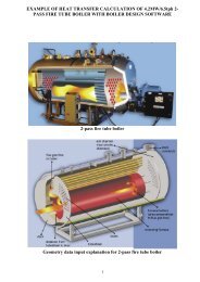
• two-pass design (see Figure 2);<br />
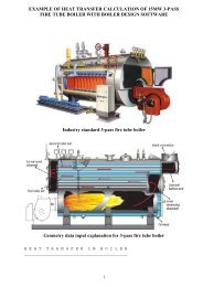
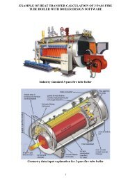
• three-pass design (see Figure 1);<br />
• four-pass design (same as the three-pass design, but with one additional<br />
<strong>tube</strong> assembly).<br />
Basically, all these families are pretty much the same. The primary difference<br />
is <strong>in</strong> how many times the flue-gases change direction <strong>in</strong>side the <strong>boiler</strong> and<br />
how many <strong>tube</strong> assemblies there are.<br />
1
In the case of the two-pass design, there is a s<strong>in</strong>gle <strong>tube</strong> assembly, so the<br />
flue-gases must usually make a 180° turn at the rear of furnace back towards<br />
the door before be<strong>in</strong>g able to enter the <strong>tube</strong>s 1 . Boilers of a three-pass design<br />
(see Figure 1) feature two assemblies of <strong>tube</strong>s, so there is no turn at the<br />
furnace rear back to the door as the flue-gases go directly <strong>in</strong>to first <strong>tube</strong><br />
assembly and from there, turn 180° as they enter the second <strong>tube</strong> assembly.<br />
The four-pass design is the same as the three-pass only with one more <strong>tube</strong><br />
assembly result<strong>in</strong>g <strong>in</strong> more <strong>tube</strong>s and direction changes.<br />
Interest<strong>in</strong>gly, the number of passes does not affect the extraction of <strong>heat</strong> from<br />
the flue-gases on their way through the <strong>in</strong>terior of the <strong>boiler</strong>. Rather, the<br />
amount of extracted <strong>heat</strong> depends solely on how much cooled <strong>heat</strong> <strong>transfer</strong><br />
surface area there is, how it is distributed (f.i. how much area is located <strong>in</strong><br />
furnace and <strong>in</strong> <strong>tube</strong>s) and on the velocity of flue-gases. More passes do not<br />
mean more efficiency; it only results <strong>in</strong> more reversals of the flue-gases flow.<br />
Thus, from the <strong>heat</strong> <strong>transfer</strong> po<strong>in</strong>t of view, there is no advantage of the three-<br />
and four-pass designs over the two-pass one. Further, more passes means<br />
higher cost and weight of the <strong><strong>boiler</strong>s</strong> because of the <strong>in</strong>troduction of more <strong>tube</strong><br />
assemblies, which are up to three times more expensive than <strong>boiler</strong> steel<br />
plates.<br />
<strong>tube</strong>s<br />
furnacefirst<br />
pass<br />
direct <strong>tube</strong>ssecond<br />
pass<br />
front<br />
FRONT VIEW<br />
LONGITUDINAL CROSS-SECTION<br />
return <strong>tube</strong>s-<br />
third pass<br />
REAR VIEW<br />
Figure 1: Fire-<strong>tube</strong> steam <strong>boiler</strong> <strong>in</strong> conventional three-pass design<br />
rear<br />
steam space<br />
water l<strong>in</strong>e<br />
direct <strong>tube</strong>s-<br />
second pass<br />
1 This is so called revers<strong>in</strong>g furnace type. There are also two-pass <strong><strong>boiler</strong>s</strong> where flue-gases take the<br />
same path as <strong>in</strong> three-pass <strong><strong>boiler</strong>s</strong>. These <strong><strong>boiler</strong>s</strong> require the flue at the front of <strong>boiler</strong>, above the burner.<br />
2
Three- and four-pass <strong>fire</strong>-<strong>tube</strong> <strong>boiler</strong> designs have only one advantage over<br />
the two-pass one, they elim<strong>in</strong>ate the need for a 180° flue-gases reversal at<br />
the rear of furnace. As a result, the dwell-time of the combustion products<br />
and, hence, the reactants <strong>in</strong>volved <strong>in</strong> NOx formation, is shorter result<strong>in</strong>g <strong>in</strong><br />
approximately up to 20% lower NOx - emissions compared to the two-pass<br />
revers<strong>in</strong>g design. As some reductions <strong>in</strong> NOx - emission can be achieved by<br />
relatively simple and <strong>in</strong>expensive means (see Figure 7), along with the new<br />
generation of burners, lower NOx - emissions regardless the type of <strong>boiler</strong> are<br />
possible. Hence, there is noth<strong>in</strong>g advantageous <strong>in</strong> the three- and four-pass<br />
<strong>boiler</strong> designs over two-pass 2 one.<br />
Thus, a two-pass <strong>boiler</strong> design with revers<strong>in</strong>g furnace was chosen for test<br />
<strong><strong>boiler</strong>s</strong> (see Figure 2) and several actual-sized two-pass <strong>fire</strong>-<strong>tube</strong>, 450 kW, hot<br />
water <strong><strong>boiler</strong>s</strong> were built and a series of tests was run on them. For the<br />
purpose of more extensive validation of the algorithm, a 4MW 10bar <strong>in</strong>dustrialsized<br />
steam <strong>boiler</strong> was also built and put to the tests. S<strong>in</strong>ce contemporary<br />
commercial fan burners were applied, the 100% combustion efficiency was<br />
achieved elim<strong>in</strong>at<strong>in</strong>g an additional error source due to unburned fuel as <strong>in</strong> the<br />
case of solid fuels. The test <strong><strong>boiler</strong>s</strong> were completely thermally <strong>in</strong>sulated,<br />
<strong>in</strong>clud<strong>in</strong>g their doors, <strong>in</strong> order to m<strong>in</strong>imize the jacket losses, which were<br />
measured separately and taken <strong>in</strong>to account <strong>in</strong> the calculations.<br />
burner<br />
open<strong>in</strong>g<br />
front side of<br />
furnace<br />
(area: 0.227m 2 )<br />
646mm<br />
880mm<br />
<strong>tube</strong> assembly/<br />
second pass<br />
(area: 6.124m 2<br />
)<br />
1429mm<br />
26 <strong>tube</strong>s of 51.4mm diameter<br />
and 2.6 mm wall thickness<br />
1400mm<br />
exit from furnace -<br />
flue-gases temp. measur<strong>in</strong>g po<strong>in</strong>ts no.1-4<br />
(protected thermocouples)<br />
flue-gases flow direction<br />
furnace/first pass<br />
(cyl<strong>in</strong>drical area: 3.936m 2<br />
)<br />
exit from <strong>boiler</strong> -<br />
flue-gases temp.<br />
measur<strong>in</strong>g po<strong>in</strong>t<br />
no.5 (protected<br />
thermocouple)<br />
furnace<br />
rear wall<br />
(area: 0.327m 2 )<br />
smoke chamber<br />
at exit<br />
Figure 2: Dimensions of <strong>fire</strong>-<strong>tube</strong> hot water test <strong>boiler</strong> <strong>in</strong> a two-pass design with a revers<strong>in</strong>g<br />
furnace<br />
2<br />
The two-pass <strong>boiler</strong> with revers<strong>in</strong>g furnace turns <strong>in</strong>to semi three-pass one by add<strong>in</strong>g the hot <strong>tube</strong> <strong>in</strong> the<br />
furnace accord<strong>in</strong>g to Figure 5.<br />
3
A different number and size of <strong>tube</strong>s were used on the test <strong><strong>boiler</strong>s</strong>. The test<br />
<strong><strong>boiler</strong>s</strong> featured vary<strong>in</strong>g <strong>in</strong>ternal. Emissions were measured and evaluated<br />
us<strong>in</strong>g a 3% rest oxygen <strong>in</strong> the flue-gases as a reference po<strong>in</strong>t <strong>in</strong> order to<br />
assure comparability of results.<br />
measur<strong>in</strong>g po<strong>in</strong>t no.3<br />
for exit temp. from<br />
furnace<br />
<strong>boiler</strong> shell<br />
measur<strong>in</strong>g po<strong>in</strong>t no.1<br />
for exit temp. from<br />
furnace<br />
<strong>tube</strong>s<br />
measur<strong>in</strong>g po<strong>in</strong>t no.4<br />
for exit temp. from<br />
furnace<br />
furnace<br />
measur<strong>in</strong>g po<strong>in</strong>t no.2<br />
for exit temp. from<br />
furnace<br />
Figure 3: Flue-gases exit temperature-measur<strong>in</strong>g po<strong>in</strong>ts <strong>in</strong> furnace of hot water test <strong>boiler</strong><br />
4
2. Test <strong>boiler</strong> No. 1: 450 kW hot water <strong>boiler</strong> <strong>in</strong> conventional 2-pass<br />
design<br />
The <strong>boiler</strong> shown <strong>in</strong> Figure 4 has a cyl<strong>in</strong>drical revers<strong>in</strong>g furnace, and one set<br />
of straight <strong>tube</strong>s. Here, the flue-gases travel all the way to rear of the furnace<br />
where they make a 180° turn. From there, the flue-gases return to the door <strong>in</strong><br />
front where they make another 180° turn <strong>in</strong>to the <strong>tube</strong>s. From these <strong>tube</strong>s, the<br />
flue-gases assemble <strong>in</strong> the exit smoke chamber from where they enter the<br />
stack. It should be noted that <strong>in</strong> all cases, the test <strong><strong>boiler</strong>s</strong> were entirely<br />
thermally <strong>in</strong>sulated <strong>in</strong>clud<strong>in</strong>g the door to m<strong>in</strong>imize jacket-losses, which were<br />
also measured and taken <strong>in</strong>to account <strong>in</strong> the calculations.<br />
uncooled door<br />
coiled-wire turbulators<br />
Figure 4: Test <strong>boiler</strong> No. 1<br />
revers<strong>in</strong>g furnace<br />
(first pass)<br />
thermal <strong>in</strong>sulation<br />
rear smoke chamber<br />
stack connection<br />
flue-gases path <strong>in</strong> <strong>boiler</strong><br />
<strong>tube</strong> assembly<br />
(second pass)<br />
5
3. Test <strong>boiler</strong> No. 2: Hot <strong>tube</strong> <strong>in</strong> furnace<br />
As shown <strong>in</strong> figure the first test <strong>boiler</strong>’s furnace was added a hot <strong>tube</strong> of 3 mm<br />
thickness made of <strong>fire</strong>-resistant steel.<br />
r<strong>in</strong>g-slot around hot <strong>tube</strong><br />
Figure 5: Test <strong>boiler</strong> No. 2<br />
hot <strong>tube</strong><br />
6
4. Test <strong>boiler</strong> No. 3: 450 kW hot water <strong>boiler</strong> with cooled door<br />
Added to second test <strong>boiler</strong> configuration was a water-cooled door (see Figure<br />
6). The cooled door 3 presents additional cooled surfaces <strong>in</strong> the furnace, which<br />
reta<strong>in</strong>s its same dimensions. In this case, the cooled door area represents<br />
more than 10% of the furnace area. The follow<strong>in</strong>g effects were expected:<br />
• An <strong>in</strong>tensified <strong>heat</strong> exchange <strong>in</strong> the furnace due to more cooled surfaces;<br />
• An improved efficiency attributable to the <strong>in</strong>tensified <strong>heat</strong> exchange;<br />
• A lowered surface temperature result<strong>in</strong>g <strong>in</strong> reduced jacket losses.<br />
Figure 6: Test <strong>boiler</strong> No. 3<br />
The cooled-door design conta<strong>in</strong>s two <strong>tube</strong>s (9, 10) made of rubber 4 capable to<br />
resist the temperature of <strong>boiler</strong> water (s<strong>in</strong>ce it is <strong>tube</strong>-shaped it is also is<br />
capable of resist<strong>in</strong>g he pressures higher than what the <strong>boiler</strong> itself is designed<br />
to withstand). The door walls are pla<strong>in</strong> and strengthened by anchors (4). The<br />
<strong>boiler</strong> water (1) comes <strong>in</strong> the door (5) pass<strong>in</strong>g an elbow (17), placed <strong>in</strong>to the<br />
3<br />
A practical advantage of the cooled door is an absence of the refractory which lowers the ma<strong>in</strong>tenance<br />
cost of a <strong>boiler</strong>.<br />
4<br />
If regulations do not permit the rubber a bent steel <strong>tube</strong> can be used <strong>in</strong>stead.<br />
7
eturn <strong>tube</strong> (16) caus<strong>in</strong>g an <strong>in</strong>jection effect, <strong>tube</strong> (15), another elbow (14),<br />
flexible <strong>tube</strong> (9) and third elbow (7). There is also a built-<strong>in</strong> vertical plate<br />
separat<strong>in</strong>g the door halves herewith enabl<strong>in</strong>g directed water flow with<strong>in</strong> the<br />
door. Water (1) leaves the door on the top through elbow (11) and flexible<br />
<strong>tube</strong> (10) <strong>in</strong>to advance flow <strong>tube</strong> (12) hav<strong>in</strong>g <strong>in</strong>side of it an elbow (13) of same<br />
direction as that <strong>in</strong> the return <strong>tube</strong> caus<strong>in</strong>g a suction effect of water from the<br />
door.<br />
The flexible <strong>tube</strong> connections to the door and water jacket were realized by<br />
flanges (8). The waterside resistance is not noticeably <strong>in</strong>creased despite of<br />
the additional elements. Thus, there are no additional requirements on the<br />
pump. Tests showed the water temperatures <strong>in</strong> the door and rest of the <strong>boiler</strong><br />
to be almost equal.<br />
5. Test <strong>boiler</strong> No. 4: Increase of cooled door area<br />
Figure 7 shows a <strong>boiler</strong> door design, which further <strong>in</strong>tensifies the <strong>heat</strong><br />
exchange <strong>in</strong> the furnace by further <strong>in</strong>creas<strong>in</strong>g the cooled door area. There is a<br />
short cyl<strong>in</strong>der (6) on the <strong>in</strong>ner side (3) of the <strong>boiler</strong> door (2), which is cooled<br />
(4) by the water circulat<strong>in</strong>g <strong>in</strong> the door (2). The cyl<strong>in</strong>der (6) is horizontally<br />
taperless and partly embraces the flame (8). The thickness of water-flow<br />
cross-section (4) <strong>in</strong> the cyl<strong>in</strong>der (6) was 30 mm (to prevent water circulation<br />
problems and local evaporation). On the test <strong>boiler</strong>, the outer diameter of the<br />
cyl<strong>in</strong>der (6) was 490 mm, the <strong>in</strong>side diameter was 406 mm, and its length was<br />
250 mm.<br />
The follow<strong>in</strong>g additional effects were expected:<br />
Due to cool<strong>in</strong>g (4) of cyl<strong>in</strong>der (6) and, therefore, the vic<strong>in</strong>ity of additional<br />
cooled surfaces to the flame (8), a more <strong>in</strong>tense cool<strong>in</strong>g of the <strong>in</strong>itial part of<br />
the flame (8) is enabled caus<strong>in</strong>g a decrease <strong>in</strong> NOx - emissions. The flame<br />
temperature is also partly reduced due to a cool<strong>in</strong>g effect caused by the fluegases<br />
expansion while exit<strong>in</strong>g the cyl<strong>in</strong>der (6) because its <strong>in</strong>side (5) diameter<br />
is smaller than that of the furnace (9). There is further a local recirculation of<br />
the (partly cooled) flue-gases (7) back to the flame. The follow<strong>in</strong>g process<br />
accomplishes this:<br />
1. The <strong>in</strong>side diameter (5) of cyl<strong>in</strong>der (6) is smaller than that of the furnace;<br />
2. The same quantity of flue-gases pass <strong>in</strong> the same time period as first short<br />
cross-section (5) of the cyl<strong>in</strong>der (6) and then the larger section of the<br />
furnace;<br />
3. Due to the diameter differential, the flue-gases velocity at the exit of the<br />
cyl<strong>in</strong>der (6) accord<strong>in</strong>gly slows down;<br />
4. Slow<strong>in</strong>g down the flue-gases flow generates a local pressure <strong>in</strong>crease at<br />
the cyl<strong>in</strong>der (6) exit;<br />
5. Because there is higher local pressure at the exit of the cyl<strong>in</strong>der (6) than at<br />
its <strong>in</strong>terior (5), part of the already partly cooled flue-gases is sucked back<br />
<strong>in</strong>to the flame (8), further lower<strong>in</strong>g its temperature and, thus, NOx<br />
production.<br />
8
The cyl<strong>in</strong>der’s 5 (6) <strong>in</strong>ner and outer diameters were adapted to match the<br />
spr<strong>in</strong>kl<strong>in</strong>g angle of the burner nozzle to avoid a contact of flame with<br />
surround<strong>in</strong>g walls of cyl<strong>in</strong>der (6). This would cause an under-cool<strong>in</strong>g of the<br />
flame and, thereby, production of soot and <strong>in</strong>creased CO emissions.<br />
Figure 7: Test <strong>boiler</strong> No. 4<br />
5 With a new generation of low NOx burners this cyl<strong>in</strong>der is no longer necessary as the effect, it causes,<br />
is generated by burner’s head design. This <strong>boiler</strong> served only as test <strong>boiler</strong>.<br />
9
6. Test <strong>boiler</strong> No. 5: Industrial-sized 4MW 10 bar steam <strong>boiler</strong><br />
S<strong>in</strong>ce, the hot water test <strong><strong>boiler</strong>s</strong> were relatively small, the test results obta<strong>in</strong>ed<br />
on them cannot be treated as generally applicable for all sizes of <strong>boiler</strong>. Thus,<br />
for the purpose of extended check<strong>in</strong>g of the thesis expla<strong>in</strong>ed before, an<br />
<strong>in</strong>dustrial-sized steam <strong>boiler</strong> of 4MW, 10 bar was designed. The <strong>boiler</strong> was<br />
built accord<strong>in</strong>g to the ASME Boiler and Pressure Vessel Code, Section I<br />
(1998).<br />
The steam test <strong>boiler</strong> depicted <strong>in</strong> Figure 8 and Figure 9 was built the same<br />
way as its hot water counterparts (2-pass design with revers<strong>in</strong>g furnace) and<br />
was also fully functional 6 . Added features used on test <strong><strong>boiler</strong>s</strong> No. 2 and No. 3<br />
are the cooled door, the hot <strong>tube</strong> of high temperature resistant material (see<br />
Figure 11) <strong>in</strong> the furnace, which is corrugated, and full-<strong>tube</strong>-length coiled-wire<br />
turbulators. There are 75 <strong>tube</strong>s of 62.6 mm <strong>in</strong> with 4.213 m <strong>in</strong> length as shown<br />
<strong>in</strong> Figure 16. The furnace is 3.946 m long and 1.52 m <strong>in</strong> diameter (1.35 m<br />
when corrugated).<br />
Dur<strong>in</strong>g the tests, a <strong>fire</strong>-resistant steel was used as hot <strong>tube</strong> material <strong>in</strong> test<br />
<strong>boiler</strong> No. 5 (see Figure 11) as well <strong>in</strong> other test <strong><strong>boiler</strong>s</strong>. In actual application<br />
the steel was found not applicable <strong>in</strong> <strong><strong>boiler</strong>s</strong> beyond 500 kW because the hot<br />
<strong>tube</strong> starts sagg<strong>in</strong>g over time under its own weight when hot. This is avoided<br />
by use of ceramic and the hot <strong>tube</strong> is then made <strong>in</strong> segments (see Figure 9<br />
and Figure 12). With a reference to steel, the ceramic used has a lower<br />
thermal conductivity but a higher surface emissivity, which does not change<br />
with the temperature as this is the case with steel (it is additionally several<br />
times lighter and cheaper then <strong>fire</strong>-resistant steel). It was observed that with a<br />
ceramic hot <strong>tube</strong> the <strong>heat</strong> exchange <strong>in</strong> the furnace was nearly the same,<br />
namely not affected, compared to the hot <strong>tube</strong> made of steel.<br />
Thus, the test <strong>boiler</strong> No.5 <strong>in</strong> actual application (Figure 9 and Figure 10) has<br />
the hot <strong>tube</strong> <strong>in</strong> the furnace made of ceramic (see Figure 12). Such a hot <strong>tube</strong><br />
<strong>in</strong> this <strong>boiler</strong> is made-up of 7 segments, each 530 mm long and 35 mm thick.<br />
Each segments consists of 4 parts, 2 upper and 2 lower parts with legs<br />
attached by a side and at the bottom of the lower 2 segments. In <strong>boiler</strong> the<br />
segments are l<strong>in</strong>ed-up with each other so they measure 3.71 m <strong>in</strong> length <strong>in</strong><br />
total.<br />
Boiler (1) is placed on legs (4). Boiler water below water l<strong>in</strong>e (23) is <strong>in</strong> the<br />
<strong>boiler</strong> (1) and the door (13). The steam space <strong>in</strong> the <strong>boiler</strong> and door is located<br />
above water l<strong>in</strong>e (23). On their outsides, door (13) and <strong>boiler</strong> (1) are clad with<br />
a thermally <strong>in</strong>sulated jacket (25). The flame is observed through aperture (15)<br />
located <strong>in</strong> the door (13). The burner is attached to the door (13) on mount<strong>in</strong>g<br />
plate (14). Water level gauges (16) are located on <strong>boiler</strong> (1) and door (13).<br />
The flue-gases exit through outlet (2) at the rear of the <strong>boiler</strong> (1). On the <strong>in</strong>side<br />
of the door (13), the flue-gases are diverted <strong>in</strong>to a <strong>tube</strong> assembly where a<br />
6 Three of them were built, sold and <strong>in</strong>stalled at Tucson Medical Center Healthcare <strong>in</strong> Tucson, Arizona,<br />
U.S.A. <strong>in</strong> spr<strong>in</strong>g 1999. Their performances are monitored on an ongo<strong>in</strong>g basis. See<br />
www.<strong>warga</strong><strong>boiler</strong>.com.<br />
10
Figure 8: Test <strong>boiler</strong> No. 5<br />
partition (24) made of <strong>fire</strong>-resistant steel prevented the hot flue-gases to enter<br />
the <strong>boiler</strong> (1) and door (13) above the water l<strong>in</strong>e (23).<br />
A portion of the <strong>boiler</strong> water travels from <strong>boiler</strong> (1) bottom via pipes (6), (7),<br />
(9), (11), and (12) <strong>in</strong>to the door (13) via the connected vessels pr<strong>in</strong>ciple. The<br />
water <strong>in</strong> door (13) turns <strong>in</strong>to steam above water level l<strong>in</strong>e (23), exits the door<br />
(13) through pipes (18) and (20), enters the <strong>boiler</strong> (1) steam area above water<br />
l<strong>in</strong>e (23) and leaves the <strong>boiler</strong> (1) via the steam outlet (22). The part (21)<br />
11
elow pipe (20), which delivers the steam from the door (13) <strong>in</strong>to the <strong>boiler</strong> (1)<br />
prevents the steam com<strong>in</strong>g from the door (13) from gett<strong>in</strong>g <strong>in</strong> touch with the<br />
<strong>boiler</strong> water, thereby prevent<strong>in</strong>g it from gett<strong>in</strong>g wet.<br />
Pipes (7), (11), (18), and (20) are flanged (5), (10), and (19) for the purpose of<br />
mak<strong>in</strong>g it possible to open the door (13), and for the removal of deposits from<br />
the <strong>boiler</strong> (1) bottom. Connections (3) and (8) are provided on the underside<br />
of the <strong>boiler</strong> (1) for dra<strong>in</strong><strong>in</strong>g the <strong>boiler</strong> water, and for the removal of deposits<br />
from <strong>boiler</strong> (1) bottom. The solids are <strong>in</strong> an ongo<strong>in</strong>g process removed from<br />
<strong>boiler</strong> and door (13) from water surface (23) via pipe (17).<br />
In the case of hot water <strong><strong>boiler</strong>s</strong> of such design, a pump (26) to pipe (20) is<br />
added thereby assur<strong>in</strong>g sufficient water flow <strong>in</strong> and out of the door (13). Also,<br />
a valve (27) makes it possible to open the <strong>boiler</strong> door (13) without empty<strong>in</strong>g<br />
entire <strong>boiler</strong> (1).<br />
pressure controls<br />
connection<br />
blockade to prevent<br />
hot gases contact<br />
uncooled area<br />
water column<br />
connection on door<br />
(another one side-<br />
mounted on <strong>boiler</strong>)<br />
water space<br />
<strong>in</strong> door<br />
diagonal<br />
stay-bars<br />
steam space<br />
<strong>in</strong> door<br />
front flame observ<strong>in</strong>g<br />
aperture<br />
steam connection<br />
of door with <strong>boiler</strong><br />
door steam flow<br />
dispeller<br />
safety valve<br />
connection<br />
burner<br />
ma<strong>in</strong> steam valve connection<br />
removal of water<br />
droplets <strong>in</strong> steam<br />
man hole<br />
(another two at each<br />
<strong>boiler</strong> side)<br />
water connection of<br />
<strong>boiler</strong> with door<br />
primary low water cut-off connection<br />
secondary low water cut-off connection<br />
<strong>in</strong> comb<strong>in</strong>ation with pump controller<br />
steam space <strong>in</strong> <strong>boiler</strong><br />
<strong>boiler</strong> leg<br />
thermal <strong>in</strong>sulation<br />
water space <strong>in</strong> <strong>boiler</strong><br />
Figure 9: Test <strong>boiler</strong> No. 5 as <strong>in</strong> actual operation<br />
lift<strong>in</strong>g loop<br />
removable cyl<strong>in</strong>der made of<br />
ceramic segments<br />
sta<strong>in</strong>less steel jacket<br />
feedwater <strong>in</strong>let connections<br />
completely submerged<br />
corrugated furnace<br />
bottom blow-down connection/<br />
<strong>boiler</strong> fill<strong>in</strong>g/dra<strong>in</strong><strong>in</strong>g<br />
vent<strong>in</strong>g valve connection<br />
flue-gases exit box<br />
with stack connection<br />
condensate dra<strong>in</strong><strong>in</strong>g<br />
dur<strong>in</strong>g cold start<br />
flue-gases path <strong>in</strong> <strong>boiler</strong><br />
rear flame observ<strong>in</strong>g<br />
aperture<br />
rear manhole<br />
12<br />
water l<strong>in</strong>e<br />
coiled-wire turbulence<br />
promoters made of<br />
<strong>fire</strong>-resistant steel<br />
smoke <strong>tube</strong>s
Figure 10: Test <strong>boiler</strong> No. 5 as <strong>in</strong> actual operation with door open<br />
Figure 11: Hot <strong>tube</strong> of <strong>fire</strong>-resistant steel <strong>in</strong> furnace of test <strong>boiler</strong> No.5 as dur<strong>in</strong>g tests<br />
13
Figure 12: Ceramic hot <strong>tube</strong> segment <strong>in</strong> furnace of test <strong>boiler</strong> No. 5 as <strong>in</strong> actual operation<br />
7. Choos<strong>in</strong>g the turbulators’ geometry<br />
The coiled-wire turbulator geometry was chosen accord<strong>in</strong>g to follow<strong>in</strong>g criteria<br />
and f<strong>in</strong>d<strong>in</strong>gs:<br />
• The turbulators shall tightly fit <strong>in</strong>to each <strong>tube</strong>. Hence, the basis turbulator<br />
diameter was chosen to be at most 1 mm less than the <strong>in</strong>ternal <strong>tube</strong><br />
diameter;<br />
• The pitch must be of sufficient length so the basis pitch was chosen to be<br />
approximately the same as the <strong>tube</strong> net diameter;<br />
• Each turbulator must be of sufficient length so the m<strong>in</strong>imum length was<br />
chosen to be one-third <strong>tube</strong> length, whereas experiments were also<br />
conducted with turbulators of two-thirds and full <strong>tube</strong> lengths.<br />
A series of tests was run on a test <strong><strong>boiler</strong>s</strong> with coiled-wire turbulators of<br />
various diameters, lengths, wire diameters, and pitches (see Figure 13, Figure<br />
14, Figure 15 and Figure 16). The purpose of these tests was to f<strong>in</strong>d out how<br />
the <strong>heat</strong> <strong>transfer</strong> and pressure drop are affected by these vary<strong>in</strong>g parameters,<br />
14
and also which pitch/wire-diameter/diameter/length comb<strong>in</strong>ation is <strong>in</strong> best<br />
agreement with the analytical predictions of the <strong>heat</strong> <strong>transfer</strong> and pressure<br />
drop <strong>in</strong> the <strong>tube</strong>s.<br />
36.5<br />
36<br />
500<br />
40<br />
1429<br />
Figure 13: The dimensions of <strong>tube</strong>s and turbulators used <strong>in</strong> 30-<strong>tube</strong> hot water test <strong>boiler</strong><br />
51<br />
48<br />
500<br />
50<br />
1360<br />
Figure 14: The dimensions of <strong>tube</strong>s and turbulators used <strong>in</strong> 26-<strong>tube</strong> hot water test <strong>boiler</strong><br />
d<br />
h<br />
l<br />
δ<br />
L<br />
l=1/3 L, 2/3 L, L D=51 mm<br />
d=45, 48, 50 mm L=1470 mm<br />
δ = 6, 8 mm<br />
h=10, 25, 35, 53, 65 mm<br />
Figure 15: Additional palette of coiled-wire turbulators used <strong>in</strong> 26-<strong>tube</strong> hot water test <strong>boiler</strong><br />
10<br />
5<br />
D<br />
15
h<br />
d D l=L<br />
l<br />
L<br />
δ<br />
D=62.6 mm<br />
L=4213 mm<br />
h=53 mm<br />
d=62 mm<br />
δ = 5 mm<br />
Figure 16: Dimensions of <strong>tube</strong>s and turbulators <strong>in</strong> 75-<strong>tube</strong> 4MW steam test <strong>boiler</strong><br />
8. Heat <strong>transfer</strong> tests<br />
The data collection began after each test <strong>boiler</strong> reached the steady state<br />
condition. Average values, <strong>boiler</strong> outputs, and efficiencies were calculated by<br />
equations given earlier <strong>in</strong> this section. The tests were run at differ<strong>in</strong>g <strong>boiler</strong><br />
loads with fuel oil and natural gas. The test results were compared to<br />
calculated.<br />
Experimental results and discussion on Mean Radiant Temperature, MRT<br />
The tables and graphs to follow show the representative results of comparison<br />
between the measured and calculated <strong>heat</strong> <strong>transfer</strong> <strong>in</strong> test <strong><strong>boiler</strong>s</strong>, at different<br />
<strong>boiler</strong> loads, us<strong>in</strong>g <strong>in</strong>troduced, new and exist<strong>in</strong>g, old equations for MRT. It is<br />
quite evident that, for all parameters be<strong>in</strong>g held constant, the <strong>heat</strong> <strong>transfer</strong><br />
results are <strong>in</strong> better agreement with the measured values when MRT is<br />
calculated by the new equation.<br />
Compared to the case when MRT is calculated by the new equation, the<br />
differences between the measured and calculated furnace exit temperatures<br />
are reduced to a m<strong>in</strong>imum because the <strong>in</strong>troduced equation delivers a higher<br />
MRT (17.4% <strong>in</strong> average <strong>in</strong> °C). It is also evident that differences between the<br />
calculated and measured flue-gases exit temperatures from the furnace are<br />
higher at lower <strong>boiler</strong> loads, which means the lower the <strong>boiler</strong> load the greater<br />
the error when us<strong>in</strong>g the old equation for MRT.<br />
General observations<br />
With the values obta<strong>in</strong>ed by the new equation for MRT the conditions <strong>in</strong> the<br />
furnace, when calculated by old equation are noticeably closer to the<br />
measured values (see Table 1, Graph 1, Graph 2, and Graph 3):<br />
• The flue-gases exit temperature from the furnace, when calculated by the<br />
old equation for MRT is up to 41.5% higher from that obta<strong>in</strong>ed by<br />
<strong>in</strong>troduced equation;<br />
• The calculated total <strong>heat</strong> exchange <strong>in</strong> the furnace, when calculated by the<br />
old equation for MRT is up to 13.8% less;<br />
• The radiant <strong>heat</strong> exchange <strong>in</strong> the furnace, when calculated by the old<br />
equation for MRT is up to 43.7% less.<br />
16
oiler<br />
load<br />
%<br />
Graph 1: MRTs <strong>in</strong> furnace obta<strong>in</strong>ed by different equations<br />
Table 1: Measured and calculated conditions <strong>in</strong> furnace of test <strong>boiler</strong> by different equations for<br />
MRT<br />
measured<br />
furnace exit<br />
temp.<br />
°C<br />
MRT<br />
[K]<br />
1<br />
calculated<br />
furnace exit<br />
temp. with<br />
MRT by old<br />
equation for<br />
MRT<br />
°C<br />
2<br />
calculated<br />
furnace exit<br />
temp. with<br />
MRT by new<br />
equation for<br />
MRT<br />
°C<br />
relative<br />
difference<br />
(1 vs. 2)<br />
%<br />
relative<br />
difference<br />
(3 vs. 4)<br />
%<br />
measured<br />
energy output/<br />
energy <strong>in</strong>put of<br />
<strong>boiler</strong><br />
kW<br />
adiabatic<br />
combustion<br />
temp.<br />
°C<br />
117 609 727 629 +15.5 +6.7 526.3/576.4 2047<br />
100 567 713 564 +26.4 +10.2 453/493.4 2019<br />
55 447 647 457 +41.5 +13.8 248.5/269.2 1887<br />
Note: Lower fuel <strong>heat</strong><strong>in</strong>g value (42700 kJ/kg) was used to calculate the energy <strong>in</strong>put (higher<br />
fuel <strong>heat</strong><strong>in</strong>g value was 45294 kJ/kg)<br />
furnace<br />
exit<br />
temp.<br />
[°C]<br />
1800<br />
1750<br />
1700<br />
1650<br />
1600<br />
1550<br />
1500<br />
1450<br />
1400<br />
117 100 55<br />
<strong>boiler</strong> load %<br />
MRT by old equation MRT by new equation<br />
850<br />
700<br />
550<br />
400<br />
117 100 55<br />
<strong>boiler</strong> load %<br />
furnace exit temp. with MRT by old equation<br />
furnace exit temp. with MRT by new equation<br />
measured furnace exit temp.<br />
Graph 2: Exit temperatures from furnace with MRTs obta<strong>in</strong>ed by different equations<br />
17
Conclusions<br />
radiative<br />
<strong>heat</strong><br />
exchange<br />
<strong>in</strong><br />
furnace<br />
[kW]<br />
220<br />
200<br />
180<br />
160<br />
140<br />
120<br />
100<br />
117 100 55<br />
<strong>boiler</strong> load %<br />
with MRT by old equation with MRT by new equation<br />
Graph 3: Radiation <strong>in</strong> furnace with MRTs obta<strong>in</strong>ed by different equations<br />
The analytical and experimental work described above permits the follow<strong>in</strong>g<br />
conclusions on presented procedure for calculation of MRT:<br />
• Application of a pr<strong>in</strong>ciple of radiation as a fourth power of absolute<br />
temperature from Stefan-Boltzman’s law <strong>in</strong> derivation of the new equation<br />
for MRT gives better results than old equation, which is especially evident<br />
when there is higher difference between the two temperatures used to<br />
calculate MRT from, as found <strong>in</strong> furnaces of <strong>fire</strong>-<strong>tube</strong> <strong><strong>boiler</strong>s</strong>;<br />
• Us<strong>in</strong>g the new equation for the MRT, the <strong>heat</strong> exchange <strong>in</strong> the furnace and<br />
other sections of <strong>fire</strong>-<strong>tube</strong> <strong><strong>boiler</strong>s</strong> can be assessed with an improved<br />
accuracy. When MRT is calculated us<strong>in</strong>g the new equation for MRT the<br />
<strong>boiler</strong> cannot be optimally sized. This is especially true when determ<strong>in</strong><strong>in</strong>g<br />
the number of <strong>boiler</strong> <strong>tube</strong>s s<strong>in</strong>ce there must be a higher number of <strong>tube</strong>s <strong>in</strong><br />
order to lower the <strong>in</strong>ternal pressure drop. This cannot be accurately<br />
calculated well enough because the calculated furnace exit temperatures<br />
are higher than actually measured.<br />
• The test results imply that the new equation for MRT can also be applied<br />
for lum<strong>in</strong>ous flames s<strong>in</strong>ce the agreement between values, obta<strong>in</strong>ed from<br />
tests on several test <strong><strong>boiler</strong>s</strong> of different sizes, and calculated values was<br />
very good, and of virtually the same accuracy for both fuels used <strong>in</strong> tests<br />
(natural gas and oil).<br />
Hence, the <strong>in</strong>troduced equation for MRT can be generally applied <strong>in</strong> simplyshaped<br />
enclosures, as this is the case <strong>in</strong> the furnaces and <strong>tube</strong>s of the <strong>fire</strong><strong>tube</strong><br />
<strong><strong>boiler</strong>s</strong>, s<strong>in</strong>ce it yields better agreement between measured and<br />
calculated values of <strong>heat</strong> <strong>transfer</strong> <strong>in</strong> <strong>boiler</strong>.<br />
18
8.1 Test <strong>boiler</strong> No. 1 with 30 empty <strong>tube</strong>s<br />
The first series of tests was run on test <strong>boiler</strong> No. 1 with an empty furnace and<br />
30 empty <strong>tube</strong>s of 36.5mm net diameter each. The tests were run at differ<strong>in</strong>g<br />
loads of which Table 5 shows representative results. The first test was<br />
conducted with fuel oil, while the second and third tests were run with natural<br />
gas.<br />
test<br />
No.<br />
Table 2: Heat <strong>transfer</strong> <strong>in</strong> test <strong>boiler</strong> No. 1 with 30 empty <strong>tube</strong>s<br />
<strong>boiler</strong><br />
load<br />
%<br />
measured<br />
<strong>heat</strong> <strong>transfer</strong><br />
<strong>in</strong> <strong>boiler</strong><br />
kW<br />
calculated<br />
<strong>heat</strong> <strong>transfer</strong><br />
<strong>in</strong> <strong>boiler</strong><br />
kW<br />
measured/calculated<br />
furnace<br />
exit temp.<br />
°C<br />
relative<br />
discrepancy<br />
%<br />
1 40 181.0 187.2 442/398 +3.4<br />
2 50 230.6 239.9 - 7 +4.0<br />
3 95 426.7 418.1 652/684 -2.0<br />
450<br />
400<br />
350<br />
<strong>boiler</strong> 300<br />
output 250<br />
[kW] 200<br />
150<br />
100<br />
50<br />
0<br />
Graph 4:Output of test <strong>boiler</strong> No. 1 with 30 empty <strong>tube</strong>s<br />
furnace<br />
exit<br />
temp.<br />
[°C]<br />
Graph 5: Furnace exit temperature from test <strong>boiler</strong> No.1 with 30 empty <strong>tube</strong>s<br />
7 The display of results failed.<br />
800<br />
700<br />
600<br />
500<br />
400<br />
300<br />
200<br />
100<br />
0<br />
40 50 95<br />
measured calculated<br />
measured calculated<br />
<strong>boiler</strong> load %<br />
50 95<br />
<strong>boiler</strong> load %<br />
19
Discussion and conclusions<br />
The results <strong>in</strong> the preced<strong>in</strong>g and follow<strong>in</strong>g tables and graphs show relatively<br />
good agreement between the calculated and measured <strong>heat</strong> <strong>transfer</strong> rates.<br />
The largest discrepancy was +4.0% (test No. 1), while the smallest was -0.7%<br />
(test No. 3). It is evident that <strong>in</strong> the furnace, a part of the cooled surfaces is<br />
exposed to <strong>in</strong>creased thermal loads, namely where the <strong>heat</strong> <strong>transfer</strong> from<br />
imp<strong>in</strong>g<strong>in</strong>g jet takes place. Thus, its surface temperature is up to 100% higher<br />
than those of the surround<strong>in</strong>g walls (test No. 3 <strong>in</strong> below tables), this value<br />
grow<strong>in</strong>g with the <strong>boiler</strong> load.<br />
The convection <strong>in</strong> the furnace also <strong>in</strong>creases with the <strong>boiler</strong> load and can<br />
even exceed the radiant part. Meanwhile, the lower the <strong>boiler</strong> load, the smaller<br />
the amount of energy <strong>transfer</strong>red <strong>in</strong> the <strong>tube</strong>s. By <strong>in</strong>creas<strong>in</strong>g the <strong>boiler</strong> load,<br />
the part of the <strong>heat</strong> <strong>transfer</strong> <strong>in</strong> the <strong>tube</strong>s grows, while at the lower loads, the<br />
amount of the <strong>heat</strong> exchange <strong>in</strong> the furnace can be as high as 90% of <strong>boiler</strong><br />
<strong>heat</strong> output.<br />
Accord<strong>in</strong>g to Table 5, the velocity <strong>in</strong> the <strong>tube</strong>s at the nom<strong>in</strong>al load is 4.4 times<br />
higher than at reduced loads. This results <strong>in</strong> more than doubl<strong>in</strong>g the<br />
percentage of <strong>heat</strong> <strong>transfer</strong> versus the <strong>transfer</strong> at the reduced loads. The<br />
radiation is, due to the very small volume of the <strong>tube</strong>s, reduced to a negligible<br />
amount and represents less than 5% <strong>in</strong> the nom<strong>in</strong>al load case and 12% <strong>in</strong> the<br />
reduced load case. At reduced loads, the computed total <strong>heat</strong> <strong>transfer</strong> <strong>in</strong> the<br />
<strong>boiler</strong> was higher than actually measured. It was found that the relative<br />
discrepancy between the calculated and measured amounts of <strong>heat</strong><br />
<strong>transfer</strong>red <strong>in</strong> the <strong>boiler</strong> was not the same at all loads. It was generally<br />
observed that the discrepancy between the actual and calculated values of<br />
the furnace exit temperature becomes higher at reduced <strong>boiler</strong> loads. A<br />
plausible explanation follows.<br />
At the lower <strong>boiler</strong> loads, the flame is much shorter so there is a so-called<br />
short cut effect caused by the buoyancy of the flue-gases, which causes the<br />
flue-gases to reach the rear wall with lessened <strong>in</strong>tensity. Hence, the <strong>heat</strong><br />
<strong>transfer</strong> from the imp<strong>in</strong>g<strong>in</strong>g jet at the rear wall is greatly reduced and<br />
conditions approach the flow along the plane vertical plate. So, the convection<br />
<strong>in</strong> furnace is noticeably reduced result<strong>in</strong>g <strong>in</strong> an efficiency drop at the reduced<br />
loads. Further, the velocity <strong>in</strong> the <strong>tube</strong>s is not equal <strong>in</strong> all <strong>tube</strong>s; the upper<br />
<strong>tube</strong>s and those nearer the vertical center l<strong>in</strong>e of the furnace get more fluegases<br />
than those at each side because of flue-gases buoyancy, which comes<br />
more <strong>in</strong>to effect at reduced loads.<br />
Table 3 shows the <strong>heat</strong> exchange <strong>in</strong> the furnace assum<strong>in</strong>g the <strong>heat</strong> <strong>transfer</strong><br />
from the imp<strong>in</strong>g<strong>in</strong>g jet to the rear wall is not reduced. It is evident that due to<br />
<strong>heat</strong> <strong>transfer</strong> from imp<strong>in</strong>g<strong>in</strong>g jet, the convection is <strong>in</strong>creased from 9 up to 25<br />
times as it is flue-gases velocity dependent. Despite the rear wall area<br />
represents only 13% of total surface <strong>in</strong> the furnace, the amount of the<br />
convection makes 65%-83% of the total convection there and grows with fluegases<br />
velocity.<br />
20
Table 3: Calculated <strong>heat</strong> exchange <strong>in</strong> furnace of test <strong>boiler</strong> No. 1 with 30 empty <strong>tube</strong>s<br />
Test No. <strong>in</strong><br />
Table 2<br />
flue-gases<br />
velocity 8<br />
m/s<br />
convective <strong>heat</strong><br />
<strong>transfer</strong><br />
coefficient<br />
W/m 2 K<br />
convective <strong>heat</strong> <strong>transfer</strong><br />
coefficient from jet imp<strong>in</strong>gement<br />
on rear wall<br />
W/m 2 K<br />
radiation <strong>heat</strong><br />
<strong>transfer</strong><br />
coefficient<br />
W/m 2 K<br />
1 0.8 4.1 36.8 35.1<br />
2 0.7 3.7 34.0 25.1<br />
3 2.0 6.1 154.0 30.9<br />
Test No. <strong>in</strong><br />
Table 2<br />
convection<br />
from jet<br />
imp<strong>in</strong>gement<br />
kW<br />
total<br />
convection<br />
kW<br />
total<br />
radiation<br />
kW<br />
% of total <strong>heat</strong><br />
<strong>transfer</strong>red <strong>in</strong><br />
<strong>boiler</strong><br />
1 34.1 44.0 172.7 90.3<br />
2 22.8 33.3 139.1 91.1<br />
3 125.2 150.2 187.9 79.7<br />
Test No. <strong>in</strong><br />
Table 2<br />
temp. of rear<br />
wall<br />
°C<br />
temp. of furnace<br />
cyl<strong>in</strong>drical walls<br />
°C<br />
1 129.2 107.9<br />
2 117.9 101.3<br />
3 187.5 99.8<br />
Table 4 shows the calculations of <strong>heat</strong> exchange <strong>in</strong> the furnace at reduced<br />
loads (tests No. 1 and 2) performed under the assumption the <strong>heat</strong> <strong>transfer</strong><br />
from imp<strong>in</strong>g<strong>in</strong>g jet to the rear wall was lessened by 50%. It is clearly evident<br />
that the flue-gases temperature at the furnace exit <strong>in</strong>creased, as<br />
demonstrated by tests discussed <strong>in</strong> the section to follow. This reduces the<br />
overall <strong>heat</strong> <strong>transfer</strong> <strong>in</strong> the <strong>boiler</strong> and lessens the efficiency as result.<br />
As there is a part of the area <strong>in</strong> the <strong>tube</strong>s with a lessened <strong>in</strong>tensity of the<br />
convective <strong>heat</strong> <strong>transfer</strong> due to flue-gases buoyancy, the efficiency of the<br />
<strong>boiler</strong> is further reduced, which is more apparent <strong>in</strong> cases of numerous <strong>tube</strong>s.<br />
This gives the general direction <strong>in</strong> design<strong>in</strong>g <strong><strong>boiler</strong>s</strong>. Namely, there must be<br />
only as many <strong>tube</strong>s as are necessary. This imposes the need for an accurate<br />
<strong>heat</strong> <strong>transfer</strong> analysis <strong>in</strong> any particular <strong>boiler</strong>.<br />
Table 4: Calculated <strong>heat</strong> exchange <strong>in</strong> furnace of test <strong>boiler</strong> No. 1 with 30 empty <strong>tube</strong>s at 50%<br />
reduction of jet imp<strong>in</strong>gement<br />
Test<br />
No.<br />
<strong>in</strong><br />
Table<br />
2<br />
fluegases<br />
velocity<br />
m/s<br />
convective<br />
<strong>heat</strong> <strong>transfer</strong><br />
coefficient<br />
from jet<br />
imp<strong>in</strong>gement<br />
W/m 2 K<br />
convective<br />
<strong>heat</strong> <strong>transfer</strong><br />
coefficient<br />
W/m 2 K<br />
convection<br />
from jet<br />
imp<strong>in</strong>gement<br />
kW<br />
total<br />
convection<br />
kW<br />
calculated<br />
furnace exit<br />
temp. at 50%<br />
reduced jet<br />
imp<strong>in</strong>gement<br />
°C<br />
calculated<br />
furnace exit<br />
temp. at 100%<br />
jet imp<strong>in</strong>gement<br />
°C<br />
1 0.9 18.9 4.2 19.0 30.0 482.6 410.3<br />
2 0.7 17.3 3.8 11.9 24.6 403.1 357.6<br />
8<br />
The flue-gases velocities were calculated at average flue-gases temperature <strong>in</strong> the particular <strong>boiler</strong><br />
section.<br />
21
Test No.<br />
<strong>in</strong><br />
Table 2<br />
Table 5: Calculated <strong>heat</strong> exchange <strong>in</strong> 30 empty <strong>tube</strong>s of test <strong>boiler</strong> No. 1<br />
<strong>boiler</strong><br />
load<br />
%<br />
fluegases<br />
velocity<br />
m/s<br />
convective<br />
<strong>heat</strong> <strong>transfer</strong><br />
coefficient<br />
W/m 2 K<br />
convection<br />
kW<br />
radiation<br />
<strong>heat</strong> <strong>transfer</strong><br />
coefficient<br />
W/m 2 K<br />
radiation<br />
kW<br />
% of<br />
total <strong>heat</strong><br />
<strong>transfer</strong>red<br />
<strong>in</strong> <strong>boiler</strong><br />
2 40 2.9 11.7 13.9 1.4 1.7 8.2<br />
3 95 12.9 37.7 72.2 1.7 3.8 19.6<br />
The amount of <strong>boiler</strong> surfaces with reduced convection (the above theory) can<br />
only be guessed, thereby mak<strong>in</strong>g the accurate assessment of efficiency<br />
deterioration at reduced <strong>boiler</strong> loads nearly impossible. In the case of <strong>fire</strong>-<strong>tube</strong><br />
<strong><strong>boiler</strong>s</strong>, especially those with a revers<strong>in</strong>g furnace, the efficiency drop at<br />
reduced loads seems <strong>in</strong>evitable. Therefore, the solution to reduce or elim<strong>in</strong>ate<br />
efficiency drop due to less <strong>in</strong>tense convection at reduced loads was<br />
<strong>in</strong>troduced as discussed <strong>in</strong> follow<strong>in</strong>g section. Tests on three- and four-pass<br />
<strong>fire</strong>-<strong>tube</strong> <strong><strong>boiler</strong>s</strong> with numerous <strong>tube</strong>s were not conducted as it was assumed<br />
that similar results would occur s<strong>in</strong>ce such <strong><strong>boiler</strong>s</strong> have up to 90% of their<br />
<strong>in</strong>ternal surface located <strong>in</strong> the <strong>tube</strong>s.<br />
8.2 Test <strong>boiler</strong> No. 2 with 30 empty <strong>tube</strong>s and a hot <strong>tube</strong> <strong>in</strong> furnace<br />
Internal geometry of the test <strong>boiler</strong> No. 1 was altered by add<strong>in</strong>g the hot <strong>tube</strong><br />
(see Figure 5) of high temperature resistant material to the furnace 9 . The<br />
<strong>tube</strong>s were empty to assure comparability of results with test <strong>boiler</strong> No. 1.<br />
Tests were run at reduced and nom<strong>in</strong>al loads. The <strong>heat</strong> <strong>transfer</strong> <strong>in</strong> the <strong>boiler</strong><br />
was analyzed and compared to measured values as <strong>in</strong> the tables below.<br />
It was observed that due to the presence of the hot <strong>tube</strong>, radiation was<br />
lessened by 2.5% at reduced loads and by 6.5% at the nom<strong>in</strong>al load. The<br />
convection, on the other hand, <strong>in</strong>creased by 20%. S<strong>in</strong>ce the <strong>heat</strong> ga<strong>in</strong> <strong>in</strong> the<br />
furnace due to <strong>in</strong>creased convection was greater than loss on radiation, the<br />
total <strong>heat</strong> <strong>transfer</strong> <strong>in</strong> the furnace <strong>in</strong>creased by 2% at reduced loads up to 5.8%<br />
at nom<strong>in</strong>al loads. This leads to an efficiency <strong>in</strong>crease at the same energy<br />
<strong>in</strong>put <strong>in</strong> terms of fuel rate as <strong>in</strong> the case when the hot <strong>tube</strong> is not present.<br />
Table 6: Heat <strong>transfer</strong> <strong>in</strong> test <strong>boiler</strong> No. 2 with 30 empty <strong>tube</strong>s and hot <strong>tube</strong> <strong>in</strong> furnace<br />
test<br />
No.<br />
<strong>boiler</strong><br />
load<br />
%<br />
measured<br />
<strong>heat</strong> <strong>transfer</strong><br />
<strong>in</strong> <strong>boiler</strong><br />
kW<br />
calculated<br />
<strong>heat</strong> <strong>transfer</strong> <strong>in</strong><br />
<strong>boiler</strong><br />
kW<br />
relative<br />
discrepancy<br />
%<br />
measured/<br />
calculated<br />
furnace exit<br />
temperature<br />
°C<br />
1 40 189.6 193.0 +1.7 388/366<br />
2 50 220.6 224.4 +1.7 410/387<br />
3 50 234.7 232.5 -0.9 - 10<br />
4 70 301.6 299.6 -0.6 -<br />
5 95 427.6 431.0 +0.7 585/620<br />
9 Fire-resistant steel was used on test <strong><strong>boiler</strong>s</strong>.<br />
10 The display of results failed.<br />
22
Graph 6: Output of test <strong>boiler</strong> No. 2 with 30 empty <strong>tube</strong>s and hot <strong>tube</strong> <strong>in</strong> furnace<br />
Graph 7: Furnace exit temp. from test <strong>boiler</strong> No. 2 with 30 empty <strong>tube</strong>s and hot <strong>tube</strong> <strong>in</strong><br />
furnace<br />
Table 7: Calculated <strong>heat</strong> exchange <strong>in</strong> furnace of test <strong>boiler</strong> No. 2 with 30 empty <strong>tube</strong>s and hot<br />
<strong>tube</strong> <strong>in</strong> furnace<br />
Test No.<br />
<strong>in</strong><br />
Table 6<br />
<strong>boiler</strong><br />
power<br />
[kW]<br />
fluegases<br />
velocity<br />
<strong>in</strong>side hot<br />
<strong>tube</strong><br />
m/s<br />
450<br />
400<br />
350<br />
300<br />
250<br />
200<br />
150<br />
650<br />
600<br />
flue gas 550<br />
exit temp. 500<br />
from 450<br />
furnace<br />
400<br />
350<br />
[°C] 300<br />
250<br />
200<br />
150<br />
fluegases<br />
velocity<br />
<strong>in</strong> r<strong>in</strong>gslot<br />
around<br />
hot <strong>tube</strong><br />
m/s<br />
40 50 50 70 95<br />
measured calculated<br />
convective<br />
<strong>heat</strong><br />
<strong>transfer</strong><br />
coefficient<br />
<strong>in</strong> r<strong>in</strong>g-slot<br />
W/m 2 K<br />
<strong>boiler</strong> load %<br />
40 50 95<br />
measured calculated<br />
<strong>boiler</strong> load %<br />
convective <strong>heat</strong><br />
<strong>transfer</strong><br />
coefficient<br />
from jet<br />
imp<strong>in</strong>gement<br />
on rear wall<br />
W/m 2 K<br />
radiation<br />
<strong>heat</strong><br />
<strong>transfer</strong><br />
coefficient<br />
<strong>in</strong>side hot<br />
<strong>tube</strong><br />
W/m 2 K<br />
radiation<br />
<strong>heat</strong><br />
<strong>transfer</strong><br />
coefficient<br />
outside<br />
hot <strong>tube</strong><br />
W/m 2 K<br />
1 1.6 3.7 7.1 37.4 41.8 26.6<br />
5 4.3 10.2 12.0 176.3 49.2 31.6<br />
23
Test No.<br />
<strong>in</strong><br />
Table 6<br />
convection<br />
from jet<br />
imp<strong>in</strong>gement<br />
kW<br />
convection<br />
<strong>in</strong> r<strong>in</strong>g-slot<br />
around<br />
hot <strong>tube</strong><br />
kW<br />
total<br />
convection<br />
kW<br />
radiation to<br />
hot <strong>tube</strong><br />
kW<br />
total<br />
radiation<br />
kW<br />
% of<br />
total<br />
<strong>heat</strong><br />
<strong>transfer</strong><br />
<strong>in</strong> <strong>boiler</strong><br />
1 24.0 12.1 40.3 52.4 135.7 91.1<br />
5 143.9 26.7 181.2 68.8 176.6 83.0<br />
Test No.<br />
<strong>in</strong> Table 6<br />
temp. of<br />
rear wall<br />
°C<br />
Influence of hot <strong>tube</strong> on emissions<br />
surface temp. of<br />
hot <strong>tube</strong><br />
°C<br />
temp. of furnace<br />
cyl<strong>in</strong>drical walls<br />
°C<br />
1 123.6 810 101.6<br />
5 200.8 906 98.0<br />
As shown <strong>in</strong> Table 8, the application of a hot <strong>tube</strong> <strong>in</strong> the furnace improves the<br />
quality of the combustion. This is attributed to reductions of the CO and soot<br />
due to <strong>in</strong>creased temperature of the hot <strong>tube</strong>, while NOx - emission is<br />
practically not affected (<strong>in</strong> the best case it is only marg<strong>in</strong>ally reduced). There<br />
was even an additional side benefit observed, namely the scal<strong>in</strong>g of furnace<br />
surfaces by unburned sulfur from oil was almost elim<strong>in</strong>ated. It turns out that<br />
the sulfur burns-out on the <strong>in</strong>side hot <strong>tube</strong> walls, which <strong>heat</strong>ed up red/yellow<br />
(see Table 7).<br />
Table 8: Emissions from natural gas <strong>fire</strong>d test <strong>boiler</strong> No. 2 with 30 <strong>tube</strong>s with and without hot<br />
<strong>tube</strong> <strong>in</strong> furnace<br />
excess-air CO NOx<br />
soot<br />
-<br />
ppm ppm<br />
Ba<br />
without hot <strong>tube</strong> 1.19 40 47 0-trace<br />
with hot <strong>tube</strong> 1.15 10 43 0<br />
Discussion and conclusions<br />
The calculated values shown <strong>in</strong> Table 6 are <strong>in</strong> very good agreement with<br />
those actually measured. The largest discrepancy, which was found at<br />
reduced loads, was +1.7%. The differences between the actual and calculated<br />
furnace exit temperatures were as low as 22°C at reduced loads and 35°C at<br />
nom<strong>in</strong>al load. This proves the importance of properly consider<strong>in</strong>g the <strong>heat</strong><br />
<strong>transfer</strong> from imp<strong>in</strong>g<strong>in</strong>g jet <strong>in</strong> <strong><strong>boiler</strong>s</strong>.<br />
The hot <strong>tube</strong> causes the radiation <strong>in</strong> a furnace to drop compared to that <strong>in</strong> the<br />
furnace without the hot <strong>tube</strong>. The hot <strong>tube</strong>’s surface temperature is, compared<br />
to that of surround<strong>in</strong>g walls, much higher. The hot <strong>tube</strong> <strong>in</strong>tensifies convection<br />
by <strong>in</strong>creas<strong>in</strong>g the flue-gases velocity, this tak<strong>in</strong>g place <strong>in</strong> a r<strong>in</strong>g-slot around the<br />
hot <strong>tube</strong>. S<strong>in</strong>ce the hot <strong>tube</strong> reduces the cross-section of the furnace, the fluegases<br />
velocity <strong>in</strong>side the hot <strong>tube</strong> also <strong>in</strong>creases (up to 230% <strong>in</strong> the test<br />
<strong><strong>boiler</strong>s</strong>) contribut<strong>in</strong>g to <strong>in</strong>tensified convective <strong>heat</strong> <strong>transfer</strong> from imp<strong>in</strong>g<strong>in</strong>g jet<br />
to rear wall and door (when cooled).<br />
24
The <strong>in</strong>crease <strong>in</strong> the convective part of the <strong>heat</strong> <strong>transfer</strong> <strong>in</strong> the furnace is higher<br />
than the decrease <strong>in</strong> the radiant part, result<strong>in</strong>g <strong>in</strong> the higher total <strong>heat</strong> <strong>transfer</strong><br />
<strong>in</strong> the furnace at the same fuel rate and quality of combustion than <strong>in</strong> the case<br />
without hot <strong>tube</strong> <strong>in</strong> the furnace.<br />
Another series of tests with oil under different loads was conducted with the<br />
hot <strong>tube</strong> <strong>in</strong>stalled. The results are displayed <strong>in</strong> Table 9. Graph 8 shows a<br />
uniform grow<strong>in</strong>g efficiency trend even at reduced loads (<strong>boiler</strong> efficiency does<br />
not drop when the <strong>boiler</strong> load is reduced). This is due to the fact that fluegases<br />
are forced to go all the way to rear of the furnace before return<strong>in</strong>g to<br />
enter the <strong>tube</strong>s, thereby ma<strong>in</strong>ta<strong>in</strong><strong>in</strong>g the <strong>in</strong>tensity of the <strong>heat</strong> <strong>transfer</strong> from<br />
imp<strong>in</strong>g<strong>in</strong>g jet on the rear wall.<br />
So, <strong>in</strong> the <strong>fire</strong>-<strong>tube</strong> <strong><strong>boiler</strong>s</strong>, at <strong>in</strong>creased loads, the <strong>boiler</strong> efficiency always<br />
slightly drops due to an <strong>in</strong>crease <strong>in</strong> flue-gases exit temperature, while <strong>in</strong> <strong>fire</strong><strong>tube</strong><br />
<strong><strong>boiler</strong>s</strong> with revers<strong>in</strong>g furnace, at reduced loads, the presence of hot <strong>tube</strong><br />
<strong>in</strong> the furnace ma<strong>in</strong>ta<strong>in</strong>s the efficiency at all loads due to the <strong>in</strong>tensity of <strong>heat</strong><br />
<strong>transfer</strong> from imp<strong>in</strong>g<strong>in</strong>g be<strong>in</strong>g not only preserved but even <strong>in</strong>tensified.<br />
Table 9: Efficiency of test <strong>boiler</strong> No. 2 with 30 empty <strong>tube</strong>s and hot <strong>tube</strong> <strong>in</strong> furnace at different<br />
loads<br />
test<br />
No.<br />
<strong>boiler</strong><br />
load<br />
%<br />
measured <strong>boiler</strong><br />
output 11<br />
kW<br />
calculated <strong>heat</strong><br />
<strong>transfer</strong> <strong>in</strong> <strong>boiler</strong><br />
kW<br />
measured<br />
<strong>boiler</strong><br />
efficiency<br />
%<br />
calculated<br />
<strong>boiler</strong><br />
efficiency<br />
%<br />
1 55 249.4 (±3.0) 248.6 92.6 (±1.86) 92.3<br />
2 100 449.4 (±5.4) 453.6 91.0 (±1.82) 91.9<br />
3 115 524.3 (±6.3) 525.4 90.9 (±1.82) 91.1<br />
<strong>boiler</strong><br />
efficiency<br />
%<br />
95<br />
94<br />
93<br />
92<br />
91<br />
90<br />
89<br />
88<br />
87<br />
86<br />
85<br />
55 100 115<br />
<strong>boiler</strong> load %<br />
measured efficiency calculated efficiency<br />
Graph 8: Efficiency of test <strong>boiler</strong> No. 2 with empty 30 <strong>tube</strong>s and hot <strong>tube</strong> <strong>in</strong> furnace at different<br />
loads<br />
11 The values <strong>in</strong> brackets show range with the maximum measurement uncerta<strong>in</strong>ty of 1.22% for a <strong>boiler</strong><br />
output and 2.01% for a <strong>boiler</strong> efficiency, respectively. Example: 1.22% of 524.3kW is 6.3kW and 2.01%<br />
of 90.9% is 1.8.<br />
25
With regard to the <strong>in</strong>fluence of hot <strong>tube</strong> on the <strong>heat</strong> <strong>transfer</strong> <strong>in</strong> the <strong>boiler</strong>, the<br />
follow<strong>in</strong>g general conclusions are drawn:<br />
• An application of a hot <strong>tube</strong> <strong>in</strong> a furnace of a <strong>fire</strong>-<strong>tube</strong> <strong>boiler</strong> with a<br />
revers<strong>in</strong>g furnace impairs the radiation and <strong>in</strong>tensifies the convection;<br />
• The <strong>in</strong>crease <strong>in</strong> convection is larger than loss <strong>in</strong> radiation so total <strong>heat</strong><br />
exchange <strong>in</strong> a furnace is <strong>in</strong>tensified;<br />
• The so called short-cut effect caused by the flue-gases buoyancy at<br />
reduced loads is elim<strong>in</strong>ated, while the flue-gases are forced to go all the<br />
way to rear wall of a furnace ma<strong>in</strong>ta<strong>in</strong><strong>in</strong>g the <strong>heat</strong> <strong>transfer</strong> from imp<strong>in</strong>g<strong>in</strong>g<br />
jet at all loads;<br />
• A decrease of the furnace exit temperature results <strong>in</strong> an <strong>in</strong>creased <strong>boiler</strong><br />
efficiency compared to cases when a hot <strong>tube</strong> is not present;<br />
• The presence of the hot <strong>tube</strong> does not affect emissions of NOx while CO<br />
and soot are reduced due to the high temperature of hot <strong>tube</strong>’s <strong>in</strong>ner<br />
surface.<br />
• A side benefit caused by the hot <strong>tube</strong> is the almost complete elim<strong>in</strong>ation of<br />
scal<strong>in</strong>g of furnace’s <strong>in</strong>ternal surfaces by unburned sulfur from oil.<br />
8.3 Test <strong>boiler</strong> No. 2 with 30 <strong>tube</strong>s and coiled-wire turbulators of 1/3 rd <strong>tube</strong><br />
length<br />
The next series of tests was run on the test <strong>boiler</strong> No. 2 (see Figure 5) with<br />
coiled-wire turbulators of one-third <strong>tube</strong> length and a wire diameter of 5mm<br />
(see Figure 13). Representative results are shown <strong>in</strong> Table 10 and Table 11.<br />
Dur<strong>in</strong>g all the tests the furnace was <strong>in</strong>stalled the hot <strong>tube</strong> per Figure 5. Table<br />
12 shows the results of the <strong>heat</strong> <strong>transfer</strong> analysis <strong>in</strong> the <strong>tube</strong>s at various<br />
loads.<br />
Table 10: Results of test <strong>boiler</strong> No. 2 with 30 <strong>tube</strong>s with coiled-wire turbulators of 1/3 <strong>tube</strong><br />
length at reduced loads<br />
test<br />
No.<br />
<strong>boiler</strong><br />
load<br />
%<br />
measured <strong>heat</strong><br />
output<br />
kW<br />
calculated <strong>heat</strong><br />
output<br />
kW<br />
relative<br />
discrepancy<br />
%<br />
1 50 244.6 242.3 -0.9<br />
2 50 235.9 242.1 +2.5<br />
3 70 297.5 295.8 -0.5<br />
Table 11: Results of test <strong>boiler</strong> No. 2 with 30 <strong>tube</strong>s and coiled-wire turbulators of 1/3 <strong>tube</strong><br />
length at nom<strong>in</strong>al loads<br />
test<br />
No.<br />
<strong>boiler</strong><br />
load<br />
%<br />
measured <strong>heat</strong><br />
output<br />
kW<br />
calculated <strong>heat</strong><br />
output<br />
kW<br />
relative<br />
discrepancy<br />
%<br />
1 100 446.7 442.2 -1.0<br />
2 105 486.0 487.3 +0.2<br />
3 110 498.1 483.7 -2.8<br />
26
Table 12: Heat exchange <strong>in</strong> <strong>tube</strong>s of test <strong>boiler</strong> No. 2 with 30 <strong>tube</strong>s with coiled-wire<br />
turbulators of 1/3 <strong>tube</strong> length<br />
<strong>boiler</strong><br />
load<br />
%<br />
fluegases<br />
velocity<br />
m/s<br />
convective<br />
<strong>heat</strong> <strong>transfer</strong><br />
coefficient<br />
W/m 2 K<br />
convection<br />
kW<br />
radiation<br />
<strong>heat</strong> <strong>transfer</strong><br />
coefficient<br />
W/m 2 K<br />
radiation<br />
kW<br />
% of<br />
total <strong>heat</strong><br />
<strong>transfer</strong>red <strong>in</strong><br />
<strong>boiler</strong><br />
50 10.3 34.9 39.9 1.0 1.5 17.0<br />
100 20.5 57.3 87.8 1.4 2.7 20.4<br />
As seen <strong>in</strong> Table 12, the flue-gases <strong>tube</strong> velocities at reduced and nom<strong>in</strong>al<br />
loads <strong>in</strong>creased by 3.5 and 2.5 times, respectively, compared to the empty<strong>tube</strong><br />
configuration. Accord<strong>in</strong>gly, the convective <strong>heat</strong> <strong>transfer</strong> coefficient<br />
<strong>in</strong>creased by 2.9 and 1.5 times, respectively. Also the radiant component was<br />
further reduced to less than 3%. The percentage of <strong>heat</strong> exchange <strong>in</strong> the<br />
<strong>tube</strong>s <strong>in</strong>creased at reduced loads and rema<strong>in</strong>ed approximately unchanged at<br />
<strong>in</strong>creased loads.<br />
<strong>boiler</strong><br />
power<br />
[kW]<br />
500<br />
400<br />
300<br />
Graph 9: Output of test <strong>boiler</strong> No. 2 with 30 <strong>tube</strong>s of 1/3 <strong>tube</strong> length and coiled-wire<br />
turbulators<br />
Discussion and conclusions<br />
200<br />
50 70 100 105 110<br />
<strong>boiler</strong> load %<br />
measured calculated<br />
The calculations showed almost equally good agreement with the measured<br />
data as <strong>in</strong> the case with no turbulators. The largest discrepancy was -2.8%<br />
(third nom<strong>in</strong>al loads test). The discrepancies were approximately the same at<br />
reduced and nom<strong>in</strong>al loads. Accord<strong>in</strong>g to [14], where a m<strong>in</strong>imum error of<br />
±10% <strong>in</strong> <strong>heat</strong> exchange <strong>in</strong> <strong>tube</strong>s with turbulators was reported, this represents<br />
a sizable improvement <strong>in</strong> accuracy be<strong>in</strong>g achieved, from a m<strong>in</strong>imum ±10% to<br />
less than ±3%.<br />
27
8.4 Test <strong>boiler</strong> No. 2 with 26 <strong>tube</strong>s and coiled-wire turbulators of 1/3 rd <strong>tube</strong><br />
length<br />
The test <strong>boiler</strong> per Figure 5 was made with 26 <strong>tube</strong>s of 40% greater, 51.2 mm<br />
net <strong>tube</strong> diameter each. The turbulators of one-third <strong>tube</strong> length and of 100%<br />
greater, 10 mm wire diameter were used (see Figure 14). The <strong>boiler</strong> was run<br />
at different loads with hot <strong>tube</strong> <strong>in</strong> furnace (see Figure 5). Representative<br />
results are shown <strong>in</strong> Table 13.<br />
Table 13: Results of test <strong>boiler</strong> No. 2 with 26 <strong>tube</strong>s and coiled-wire turbulators of 1/3 <strong>tube</strong><br />
length at different loads<br />
test<br />
No.<br />
<strong>boiler</strong><br />
load<br />
%<br />
measured <strong>heat</strong><br />
output<br />
kW<br />
calculated <strong>heat</strong><br />
output<br />
kW<br />
relative<br />
discrepancy<br />
%<br />
1 95 435.8 427.4 -1.9<br />
2 95 421.4 417.5 -0.9<br />
3 80 362.0 353.9 -2.2<br />
4 70 305.4 301.8 -1.1<br />
5 60 281.6 278.1 -1.2<br />
<strong>boiler</strong><br />
power<br />
[kW]<br />
Graph 10: Output of test <strong>boiler</strong> No. 2 with 26 <strong>tube</strong>s and coiled-wire turbulators of 1/3 <strong>tube</strong><br />
length<br />
Discussion and conclusions<br />
450<br />
430<br />
410<br />
390<br />
370<br />
350<br />
330<br />
310<br />
290<br />
270<br />
250<br />
60 70 80 95 95<br />
<strong>boiler</strong> load %<br />
measured calculated<br />
The largest discrepancy between calculated and measured output of the<br />
<strong>boiler</strong> was -2.2% (third test) while the m<strong>in</strong>imum was -0.9% (second test). The<br />
discrepancies between the measured and calculated values rema<strong>in</strong>ed at the<br />
same level as <strong>in</strong> the previous cases. The accuracy of the calculations did not<br />
change despite the significant change <strong>in</strong> <strong>tube</strong>, turbulator, and wire diameters.<br />
This <strong>in</strong>dicates that the rate of <strong>heat</strong> exchange <strong>in</strong> <strong>tube</strong>s with coiled-wire<br />
turbulator may not change with change of turbulator geometry and was further<br />
researched <strong>in</strong> the section to follow.<br />
28
8.5 Test <strong>boiler</strong> No. 2 with 26 <strong>tube</strong>s with coiled-wire turbulators of different<br />
geometries<br />
Additional tests on <strong>boiler</strong> No. 2 (see Figure 5) with same turbulator length but<br />
of different geometries (see Figure 15) were conducted. The test results led to<br />
the conclusions given below.<br />
Impact of turbulator pitch, diameter, and wire diameter<br />
As is evident from Table 14, the tests clearly show the approach <strong>in</strong>troduced<br />
delivers the approximately same accuracy of calculation regardless of the<br />
turbulator pitch, diameter, and wire diameter so long as the length of<br />
turbulator is kept the same 12 . The exception is test No. 1 with turbulators of an<br />
almost m<strong>in</strong>imum possible pitch, almost equal to the wire diameter.<br />
Table 14: Results of test <strong>boiler</strong> No. 2 with 26 <strong>tube</strong>s with coiled-wire turbulators of different<br />
geometries of 1/3 <strong>tube</strong> length<br />
test<br />
No.<br />
<strong>boiler</strong><br />
load<br />
%<br />
turbulator<br />
diameter<br />
mm<br />
wire<br />
diameter<br />
pitch<br />
mm<br />
measured<br />
<strong>heat</strong><br />
<strong>transfer</strong> <strong>in</strong><br />
<strong>boiler</strong><br />
calculated<br />
<strong>heat</strong> <strong>transfer</strong><br />
<strong>in</strong> <strong>boiler</strong><br />
relative<br />
discrepancy<br />
%<br />
1 100 50 8 10 424.4 445.2 +4.9<br />
2 100 50 8 25 446.9 442.1 -1.0<br />
3 115 50 8 65 524.3 523.2 -0.2<br />
4 50 50 8 65 242.5 235.6 -2.8<br />
5 100 48 6 35 451.7 447.2 -0.9<br />
6 50 48 6 35 228.4 227.2 -0.5<br />
7 50 48 6 53 239.8 238.5 -0.5<br />
8 100 48 6 53 442.7 439.8 -0.6<br />
9 100 45 8 32 453.8 448.9 -1.0<br />
10 50 45 8 32 232.5 233.0 +0.2<br />
<strong>boiler</strong><br />
power<br />
[kW]<br />
500<br />
450<br />
400<br />
350<br />
300<br />
250<br />
200<br />
10 25 32 53 65<br />
turbulator pitch [mm]<br />
measured calculated<br />
Graph 11: Output of test <strong>boiler</strong> No. 2 with 26 <strong>tube</strong>s with coiled-wire turbulators of different<br />
geometries of 1/3 <strong>tube</strong> length<br />
12 In this case the turbulator length was one third <strong>tube</strong> length.<br />
29
Impact of turbulator length<br />
Unlike turbulator configuration, turbulator length affects the amount of<br />
convection <strong>in</strong> <strong>boiler</strong> <strong>tube</strong>s. Heat exchange <strong>in</strong> <strong>boiler</strong> <strong>tube</strong>s with turbulators<br />
longer than one third <strong>tube</strong> length can be calculated with approximately the<br />
same accuracy as with turbulators of one third <strong>tube</strong> length when the follow<strong>in</strong>g<br />
modifications are applied:<br />
1. Turbulators of two third <strong>tube</strong> length: Heat exchange <strong>in</strong> <strong>tube</strong>s is calculated<br />
based on turbulators of on third <strong>tube</strong> length multiplied by a factor of 1.1;<br />
2. Turbulators of full <strong>tube</strong> length: Heat exchange <strong>in</strong> <strong>tube</strong>s is calculated based<br />
on turbulators of on third <strong>tube</strong> length multiplied by a factor of 1.2.<br />
Table 15 and Table 16 show the representative test results when turbulators<br />
of two third and full <strong>tube</strong> length, respectively, were used.<br />
Table 15: Results of test <strong>boiler</strong> No. 2 with 26 <strong>tube</strong>s with coiled-wire turbulators of 2/3 <strong>tube</strong><br />
length<br />
test No. <strong>boiler</strong> load<br />
%<br />
measured <strong>heat</strong><br />
output<br />
kW<br />
calculated <strong>heat</strong><br />
<strong>transfer</strong> with<br />
coefficient 1.1<br />
kW<br />
relative<br />
discrepancy<br />
%<br />
1 100 453.8 448.9 -1.0<br />
2 100 448.2 450.9 +0.6<br />
3 50 232.5 233.0 +0.2<br />
4 50 237.5 232.7 -2.0<br />
Table 16: Results of test <strong>boiler</strong> No. 2 with 26 <strong>tube</strong>s with coiled-wire turbulators of full <strong>tube</strong><br />
length<br />
test No. <strong>boiler</strong> load<br />
%<br />
measured <strong>heat</strong><br />
output<br />
kW<br />
calculated <strong>heat</strong><br />
<strong>transfer</strong> with<br />
coefficient 1.2<br />
kW<br />
relative<br />
discrepancy<br />
%<br />
1 100 455.5 458.2 +0.5<br />
2 100 446.2 452.6 -1.4<br />
3 50 237.6 232.7 -2.0<br />
4 50 242.5 235.6 -2.8<br />
Discussion and conclusions<br />
The empirical coefficients suggested on the basis of the test results brought<br />
the calculation accuracy of the impact of turbulators longer than one-third <strong>tube</strong><br />
length on <strong>heat</strong> exchange to a ±2% level. Thus, the same accuracy <strong>in</strong> <strong>heat</strong><br />
<strong>transfer</strong> calculation <strong>in</strong> straight <strong>tube</strong>s with coiled-wire turbulators is ma<strong>in</strong>ta<strong>in</strong>ed<br />
over a wide range of turbulator geometries <strong>in</strong> terms of its diameter, wire<br />
diameter, pitch, and length. The results lead to conclusion that the turbulator<br />
length affects the <strong>heat</strong> exchange rate <strong>in</strong> a l<strong>in</strong>ear fashion.<br />
30
9. Tests on pressure drop<br />
9.1 Test <strong>boiler</strong> No. 2 with 26 empty <strong>tube</strong>s<br />
The flue-gases side pressure losses <strong>in</strong> a <strong>boiler</strong> significantly <strong>in</strong>fluence the<br />
operation of the <strong>boiler</strong>. In cases where there are too high flue-gases side<br />
pressure losses <strong>in</strong> the <strong>boiler</strong>, the burner fan cannot overcome the pressure.<br />
This eventually leads to flame ext<strong>in</strong>ction. So, the accuracy <strong>in</strong> the analytical<br />
assessment of pressure drop <strong>in</strong> the <strong>boiler</strong> must be ma<strong>in</strong>ta<strong>in</strong>ed. This is<br />
particularly needed when there are turbulators as they <strong>in</strong>crease the <strong>heat</strong><br />
exchange but <strong>in</strong>crease the flue-gases side pressure losses <strong>in</strong> the <strong>boiler</strong> as<br />
well.<br />
The next series of tests on <strong>boiler</strong> shown <strong>in</strong> Figure 5 with 26 <strong>tube</strong>s was run with<br />
the <strong>boiler</strong>’s <strong>in</strong>ternal flue-gases side pressure losses be<strong>in</strong>g measured.<br />
Calculations accord<strong>in</strong>g were compared to these measured values. Table 17<br />
shows representative results of the pressure-drop tests on a test <strong>boiler</strong> of<br />
conventional design with 26 empty <strong>tube</strong>s at different loads with and without a<br />
hot <strong>tube</strong> <strong>in</strong> furnace. While calculat<strong>in</strong>g the pressure drop <strong>in</strong> <strong>boiler</strong>, its <strong>in</strong>ternal<br />
geometry was taken <strong>in</strong>to account so the coefficients for the pressure drop<br />
equation were calculated separately for each <strong>boiler</strong> section. S<strong>in</strong>ce the <strong>boiler</strong><br />
<strong>tube</strong>s were empty, the friction coefficient of plane <strong>tube</strong> was used <strong>in</strong> the<br />
equation for pressure drop.<br />
Table 17: Pressure drop <strong>in</strong> test <strong>boiler</strong> No. 2 with 26 empty <strong>tube</strong>s with and without hot <strong>tube</strong><br />
<strong>boiler</strong> load<br />
%<br />
measured gas<br />
side pressure<br />
drop <strong>in</strong> <strong>boiler</strong><br />
Pa<br />
calculated gas side<br />
pressure drop <strong>in</strong><br />
<strong>boiler</strong><br />
Pa<br />
relative<br />
discrepancy<br />
%<br />
without hot <strong>tube</strong> 50 11 10.6 -3.6<br />
with hot <strong>tube</strong> 50 14 14.4 +2.8<br />
without hot <strong>tube</strong> 100 60 53 -11.6<br />
with hot <strong>tube</strong> 100 97 88 -9.2<br />
pressure<br />
drop<br />
[Pa]<br />
120<br />
100<br />
80<br />
60<br />
40<br />
20<br />
0<br />
50 100 50 100<br />
with hot <strong>tube</strong> without hot <strong>tube</strong><br />
load [%]<br />
measured calculated<br />
Graph 12: Pressure drop <strong>in</strong> test <strong>boiler</strong> No. 2 with 26 empty <strong>tube</strong>s with and without hot <strong>tube</strong><br />
31
Discussion and conclusions<br />
The presence of the hot <strong>tube</strong> <strong>in</strong> furnace causes an approximately 30%<br />
<strong>in</strong>crease <strong>in</strong> the flue-gases side pressure drop at reduced loads and an<br />
approximately 60% at nom<strong>in</strong>al loads. S<strong>in</strong>ce the <strong>boiler</strong> <strong>in</strong>ternal pressure drop <strong>in</strong><br />
the 100 Pa range is considered to be a relatively small, the presence of hot<br />
<strong>tube</strong> does not make additional requirements on the burner. The extent of the<br />
pressure drop by the hot <strong>tube</strong> is r<strong>in</strong>g-slot thickness dependent. To ma<strong>in</strong>ta<strong>in</strong> a<br />
pressure drop <strong>in</strong> the furnace to with<strong>in</strong> acceptable limits, the area of r<strong>in</strong>g-slot<br />
flow cross-section was found to need to be a m<strong>in</strong>imum 25-30% of the furnace<br />
cross-section. It was observed that, at higher loads, the percentage of the<br />
pressure drop <strong>in</strong>crease, with the hot <strong>tube</strong> <strong>in</strong> furnace, is larger than found at<br />
lesser loads (as was expected due to higher velocities at the <strong>in</strong>creased loads).<br />
The largest discrepancy between the predicted and measured pressure drop<br />
of 11.7%, can be treated as be<strong>in</strong>g sufficiently accurate. Such results were<br />
expected as the valid equations were generally applicable to empty <strong>tube</strong>s and<br />
channels, not ones accommodat<strong>in</strong>g turbulators.<br />
9.2 Test <strong>boiler</strong> No. 2 with 26 <strong>tube</strong>s with coiled-wire turbulators of different<br />
geometries<br />
Further tests were run on the <strong>boiler</strong> (see Figure 5) with the coiled-wire<br />
turbulators of vary<strong>in</strong>g geometries. Table 18 shows representative results at<br />
these loads.<br />
Discussion and conclusions<br />
As is evident from Table 18, the pressure drop and discrepancy value<br />
<strong>in</strong>creased when the turbulator pitch and diameter, compared to the <strong>tube</strong><br />
diameter, decreased. This trend is especially evident at <strong>in</strong>creased loads while<br />
less at reduced loads. It was observed that <strong>in</strong>creas<strong>in</strong>g the turbulator length did<br />
not <strong>in</strong>crease the pressure drop predication accuracy. The general conclusion<br />
is that as the turbulator pitch and diameter get smaller to the <strong>tube</strong> diameter,<br />
the higher the pressure drop and negative discrepancy between the<br />
calculated and measured values.<br />
Further tests resulted demonstrat<strong>in</strong>g that the approach used yields mostly<br />
positive discrepancies <strong>in</strong> pressure drop calculations <strong>in</strong> straight <strong>tube</strong>s with<br />
coiled-wire turbulators. These discrepancies are with<strong>in</strong> maximum +10-15%<br />
range when the turbulator pitch, diameter, length, and wire diameter match<br />
the criteria shown <strong>in</strong> Figure 17.<br />
As the calculated pressure drop was found to be typically higher than that<br />
which was actually measured, a known safety marg<strong>in</strong> factor can be assumed.<br />
This thereby prevents an overload of the burner fan, which would otherwise<br />
lead to the <strong>boiler</strong>’s <strong>in</strong>ability to reach a nom<strong>in</strong>al load as the burner would not be<br />
able to overcome the flue-gases side pressure <strong>in</strong> the <strong>boiler</strong>.<br />
32
test<br />
No.<br />
D<br />
m<strong>in</strong>. 0.8 D<br />
m<strong>in</strong>. 1/3 L<br />
L<br />
max. 0.5 mm<br />
Figure 17: Geometry of coiled-wire turbulators to assure maximum +10-15% <strong>in</strong>accuracy <strong>in</strong><br />
analytical assessment of pressure drop <strong>in</strong> <strong>tube</strong>s<br />
Table 18: Pressure drop <strong>in</strong> test <strong>boiler</strong> No. 2 with 26 <strong>tube</strong>s with turbulators of different<br />
geometries<br />
<strong>boiler</strong><br />
load<br />
[%]<br />
length<br />
[% of<br />
<strong>tube</strong>]<br />
<strong>tube</strong><br />
diameter<br />
[mm]<br />
turbulator<br />
diameter/<br />
wire<br />
diameter<br />
[mm]<br />
pitch<br />
[mm]<br />
measured<br />
pressure<br />
drop<br />
[Pa]<br />
calculated<br />
pressure<br />
drop<br />
[Pa]<br />
relative<br />
discrepancy<br />
[%]<br />
1 115 100 51 50/8 65 355 370 +4.2<br />
2 100 100 51 50/8 65 226 265 +17.2<br />
3 100 66 51 45/8 32 405 235 -41.9<br />
4 50 66 51 45/8 32 110 92 -16.3<br />
5 100 50 51 50/8 25 305 272 -10.8<br />
6 100 33 51 50/8 10 255 284 +11.3<br />
7 100 100 51 48/6 53 200 205 +2.5<br />
8 100 100 51 48/6 35 328 216 -34.1<br />
9 50 100 51 48/6 35 74 47 -36.4<br />
10 50 66 51 50/6 53 52 47 -9.6<br />
11 100 66 51 48/6 53 180 201 +11.6<br />
12 50 66 51 48/6 35 59 41 -30.5<br />
13 100 66 51 48/6 35 278 208 -25.1<br />
14 100 50 51 48/6 35 229 216 -5.6<br />
15 100 33 51 48/6 35 191 228 +25.9<br />
16 50 33 51 48/6 35 40 41 +2.5<br />
10. Tests on <strong><strong>boiler</strong>s</strong> of different furnace geometries<br />
The test <strong>boiler</strong> was gradually redesigned as shown <strong>in</strong> Figure 6 and Figure 7.<br />
The impact of each design feature on <strong>heat</strong> <strong>transfer</strong> and emissions was<br />
<strong>in</strong>vestigated and analyzed. Dur<strong>in</strong>g the tests, the hot <strong>tube</strong> (see Figure 5) was<br />
<strong>in</strong>serted <strong>in</strong> the furnace and there were one-third <strong>tube</strong> length coiled-wire<br />
turbulators <strong>in</strong> the <strong>tube</strong>s per Figure 14. All tests were run at nom<strong>in</strong>al <strong>boiler</strong><br />
loads. While calculat<strong>in</strong>g the emissions of CO and NOx, a 3% of rest oxygen <strong>in</strong><br />
the flue-gases was taken a base comparison reference.<br />
33
10.1 Comparison of test <strong><strong>boiler</strong>s</strong> No. 2 and No. 3<br />
Influence of cooled door on emissions<br />
As is evident from Table 19, show<strong>in</strong>g representative results, the door cool<strong>in</strong>g<br />
negligibly affects the CO, soot and NOx emissions. The data <strong>in</strong> the table<br />
below were obta<strong>in</strong>ed from tests with oil. Approximately same relative trend<br />
was observed <strong>in</strong> the case of natural gas. The slight decrease of NOx -<br />
emissions from the <strong>boiler</strong> with cooled door is based on a decreased average<br />
temperature <strong>in</strong> the furnace due to the additional cooled surfaces on the <strong>boiler</strong><br />
door.<br />
Table 19: Emissions from test <strong>boiler</strong> with cooled and uncooled door<br />
CO<br />
NOx<br />
soot<br />
ppm<br />
ppm<br />
Ba<br />
<strong>boiler</strong> without cooled door 40 102 0-trace<br />
<strong>boiler</strong> with cooled door 45 97 0-trace<br />
Influence on <strong>heat</strong> <strong>transfer</strong><br />
Tables below convey the analyzed <strong>heat</strong> exchange <strong>in</strong> the furnace and <strong>tube</strong>s<br />
with and without the cooled door while hold<strong>in</strong>g the other parameters of<br />
<strong>in</strong>fluence (e.g. water flow, water temperatures, fuel rate, quality of<br />
combustion) constant. S<strong>in</strong>ce <strong>in</strong> the third <strong>boiler</strong> segment, the smoke chamber<br />
at rear, there is a negligible <strong>heat</strong> exchange due to low temperature and low<br />
flue-gases velocity, the <strong>heat</strong> exchange there was not taken <strong>in</strong> consideration.<br />
exit<br />
temp.<br />
°C<br />
Table 20: Calculated <strong>heat</strong> exchange <strong>in</strong> furnace of test <strong>boiler</strong> No. 2 without cooled door<br />
flue-gases<br />
velocity<br />
<strong>in</strong>side/<br />
outside hot<br />
<strong>tube</strong><br />
m/s<br />
convective<br />
<strong>heat</strong> <strong>transfer</strong><br />
coefficient<br />
<strong>in</strong>side/<br />
outside<br />
hot <strong>tube</strong><br />
W/m 2 K<br />
convective<br />
<strong>heat</strong><br />
<strong>transfer</strong><br />
coefficient<br />
at rear<br />
wall 13<br />
W/m 2 K<br />
convection<br />
to rear wall/<br />
total<br />
convection<br />
kW<br />
radiation<br />
<strong>heat</strong> <strong>transfer</strong><br />
coefficient<br />
<strong>in</strong>side/<br />
outside hot<br />
<strong>tube</strong><br />
W/m 2 K<br />
radiation<br />
kW<br />
temp. of rear<br />
wall/<br />
other cooled<br />
surfaces<br />
°C<br />
832.6 3.9/10.4 7.5/12.3 172.0 61.2/164.9 46.5/37.1 129.0 235.2/109.4<br />
Table 21: Calculated <strong>heat</strong> exchange <strong>in</strong> <strong>tube</strong>s of test <strong>boiler</strong> No. 2 without cooled door<br />
exit<br />
temp.<br />
°C<br />
fluegases<br />
velocity<br />
m/s<br />
convective<br />
<strong>heat</strong> <strong>transfer</strong><br />
coefficient<br />
W/m 2 K<br />
convection<br />
kW<br />
radiation<br />
<strong>heat</strong> <strong>transfer</strong><br />
coefficient<br />
W/m 2 K<br />
radiation<br />
kW<br />
wall<br />
temp.<br />
°C<br />
% of total<br />
<strong>heat</strong><br />
<strong>transfer</strong>red<br />
<strong>in</strong> <strong>boiler</strong><br />
319.6 16.5 43.0 109.3 2.3 7.1 101.4 28.0<br />
13 Area of <strong>heat</strong> <strong>transfer</strong> from jet imp<strong>in</strong>gement.<br />
34
Table 22: Calculated <strong>heat</strong> exchange <strong>in</strong> furnace of test <strong>boiler</strong> No. 3 with cooled door<br />
exit<br />
temp.<br />
°C<br />
fluegases<br />
velocity<br />
<strong>in</strong>side/<br />
outside<br />
hot <strong>tube</strong><br />
m/s<br />
680.0 3.8/<br />
9.6<br />
exit<br />
temp.<br />
°C<br />
convective<br />
<strong>heat</strong><br />
<strong>transfer</strong><br />
coefficient<br />
<strong>in</strong>side/<br />
outside<br />
hot <strong>tube</strong><br />
W/m 2 K<br />
7.2/<br />
11.7<br />
convective<br />
<strong>heat</strong><br />
<strong>transfer</strong><br />
coefficient<br />
at rear wall/<br />
door 14<br />
W/m 2 K<br />
165.2/<br />
157.9<br />
convection<br />
to rear wall/<br />
door/<br />
total<br />
convection<br />
kW<br />
53.9/<br />
96.5/<br />
183.0<br />
radiation<br />
<strong>heat</strong><br />
<strong>transfer</strong><br />
coefficient<br />
<strong>in</strong>side/<br />
outside hot<br />
<strong>tube</strong><br />
W/m 2 K<br />
44.8/<br />
36.8<br />
radiation<br />
kW<br />
temp. of<br />
rear wall/<br />
door/<br />
other<br />
cooled<br />
surfaces<br />
°C<br />
146.9 214.1/<br />
189.3/<br />
106.1<br />
Table 23: Calculated <strong>heat</strong> exchange <strong>in</strong> <strong>tube</strong>s of test <strong>boiler</strong> No. 3 with cooled door<br />
fluegases<br />
velocity<br />
m/s<br />
convective<br />
<strong>heat</strong> <strong>transfer</strong><br />
coefficient<br />
W/m 2 K<br />
convection<br />
kW<br />
radiation<br />
<strong>heat</strong> <strong>transfer</strong><br />
coefficient<br />
W/m 2 K<br />
radiation<br />
kW<br />
wall<br />
temp.<br />
°C<br />
% of total<br />
<strong>heat</strong><br />
<strong>transfer</strong>red<br />
<strong>in</strong> <strong>boiler</strong><br />
280.1 14.8 41.1 84.3 1.8 4.4 99.3 21.0<br />
Discussion and conclusions<br />
The cooled door represents a 15% <strong>in</strong>crease <strong>in</strong> cooled surfaces <strong>in</strong> furnace and<br />
<strong>in</strong>tensifies <strong>heat</strong> <strong>transfer</strong> there by 10.9%. The flue-gases and exit temperatures<br />
from furnace were reduced by 8.4% and 18.3%, respectively. As the fluegases<br />
exit temperature from the <strong>boiler</strong> was lowered by 37°C, the slight<br />
<strong>in</strong>crease <strong>in</strong> <strong>boiler</strong> efficiency (by 1.7%) results. The wall temperature was<br />
almost unaffected. Radiation <strong>in</strong>creased by 13.8%, while convection <strong>in</strong>creased<br />
by 9%.<br />
While the cooled door was proven as beneficial to the <strong>boiler</strong>, it affects the NOx<br />
- emissions only slightly while the other emissions are not effected at all. The<br />
door and furnace rear wall are exposed to more <strong>in</strong>tense <strong>heat</strong> <strong>transfer</strong> from<br />
imp<strong>in</strong>g<strong>in</strong>g jet, their wall temperatures rise well above the other cooled<br />
surfaces. Due to an <strong>in</strong>tensified <strong>heat</strong> exchange <strong>in</strong> the furnace, the flue-gases<br />
enter the <strong>tube</strong>s with a lower velocity result<strong>in</strong>g <strong>in</strong> less <strong>in</strong>tense convection and<br />
radiation so the total <strong>heat</strong> exchange <strong>in</strong> <strong>tube</strong>s is reduced. As radiation<br />
represents small part of the total <strong>heat</strong> <strong>transfer</strong> <strong>in</strong> the <strong>tube</strong>s (less than 6% <strong>in</strong><br />
test <strong>boiler</strong>), its reduction is of no importance and, so it can be considered to be<br />
negligible. Further it is evident that the <strong>fire</strong>-<strong>tube</strong> <strong><strong>boiler</strong>s</strong> can be designed <strong>in</strong><br />
such a way that the convection <strong>in</strong> the furnace is higher then a radiation.<br />
Despite this design feature was <strong>in</strong>troduced for the purposes of the tests it was<br />
found as fully applicable on hot water <strong><strong>boiler</strong>s</strong> for central <strong>heat</strong><strong>in</strong>g.<br />
10.2 Test <strong>boiler</strong> No. 4<br />
Next, the test <strong>boiler</strong> cooled door surface was <strong>in</strong>creased (see Figure 7 and<br />
section 1.1.1.4). A more <strong>in</strong>tense <strong>heat</strong> <strong>transfer</strong> and pre-cool<strong>in</strong>g of the flame<br />
caused a reduction <strong>in</strong> NOx as was expected.<br />
14 Area of <strong>heat</strong> <strong>transfer</strong> from jet imp<strong>in</strong>gement.<br />
35
Influence on emissions<br />
As is evident from representative results shown <strong>in</strong> Table 24, with liquid fuels<br />
the cooled cyl<strong>in</strong>der on cooled door contributed to up to 10% less NOx<br />
production, while the CO emission was only slightly <strong>in</strong>creased and the soot<br />
emission rema<strong>in</strong>ed unchanged. With gaseous fuels there is only a marg<strong>in</strong>al<br />
change <strong>in</strong> NOx-emission and slight <strong>in</strong>crease <strong>in</strong> CO-emission with no change<br />
<strong>in</strong> soot-emission.<br />
cooled door with<br />
cooled cyl<strong>in</strong>der<br />
cooled door without<br />
cooled cyl<strong>in</strong>der<br />
Influence on <strong>heat</strong> <strong>transfer</strong><br />
Table 24: Emissions from test <strong>boiler</strong> No. 4<br />
oil natural gas<br />
NOx soot CO NOx soot CO<br />
ppm Ba ppm ppm Ba ppm<br />
90 0-trace 38 65 0 33<br />
99 0-trace 28 62 0 51<br />
Tables below depict the <strong>heat</strong> exchange <strong>in</strong> the furnace and <strong>tube</strong>s. As the<br />
cooled cyl<strong>in</strong>der on the cooled door represents an <strong>in</strong>creased amount of cooled<br />
surfaces <strong>in</strong> the furnace, the <strong>heat</strong> <strong>transfer</strong> was more <strong>in</strong>tensified and flue-gases<br />
temperatures further reduced.<br />
exit<br />
temp.<br />
°C<br />
Table 25: Calculated <strong>heat</strong> exchange <strong>in</strong> furnace of test <strong>boiler</strong> No. 4<br />
fluegases<br />
velocity<br />
<strong>in</strong>side/<br />
outside<br />
hot <strong>tube</strong><br />
m/s<br />
645.6 3.8/<br />
9.5<br />
exit<br />
temp.<br />
°C<br />
convective<br />
<strong>heat</strong><br />
<strong>transfer</strong><br />
coefficient<br />
<strong>in</strong>side/<br />
outside<br />
hot <strong>tube</strong><br />
W/m 2 K<br />
7.1/<br />
11.6<br />
convective<br />
<strong>heat</strong><br />
<strong>transfer</strong><br />
coefficient<br />
at rear wall/<br />
door<br />
W/m 2 K<br />
163.5/<br />
156.2<br />
convection<br />
to rear wall/<br />
door/<br />
total<br />
convection<br />
kW<br />
52.3/<br />
93.1/<br />
176.8<br />
radiation<br />
<strong>heat</strong><br />
<strong>transfer</strong><br />
coefficient<br />
<strong>in</strong>side/<br />
outside hot<br />
<strong>tube</strong><br />
W/m 2 K<br />
44.5/<br />
32.8<br />
radiation<br />
kW<br />
Table 26: Calculated <strong>heat</strong> exchange <strong>in</strong> <strong>tube</strong>s of test <strong>boiler</strong> No. 4<br />
fluegases<br />
velocity<br />
m/s<br />
convective<br />
<strong>heat</strong> <strong>transfer</strong><br />
coefficient<br />
W/m 2 K<br />
convection<br />
kW<br />
radiation<br />
<strong>heat</strong> <strong>transfer</strong><br />
coefficient<br />
W/m 2 K<br />
radiation<br />
kW<br />
temp. of<br />
rear wall/<br />
door/<br />
other<br />
cooled<br />
surfaces<br />
°C<br />
161.1 206.7/<br />
149.5/<br />
105.0<br />
wall<br />
temp.<br />
°C<br />
% of total<br />
<strong>heat</strong><br />
<strong>transfer</strong>red<br />
<strong>in</strong> <strong>boiler</strong><br />
270.8 14.4 40.7 78.8 1.7 3.9 98.8 19.5<br />
Discussion and conclusions<br />
A cooled cyl<strong>in</strong>der on the cooled door further <strong>in</strong>tensifies the <strong>heat</strong> exchange <strong>in</strong><br />
the furnace by <strong>in</strong>troduc<strong>in</strong>g additional cooled surfaces. The flue-gases average<br />
temperature and their exit temperature from furnace are lowered, thereby<br />
36
educ<strong>in</strong>g the <strong>heat</strong> exchange <strong>in</strong> the <strong>tube</strong>s. As the flue-gases exit temperature<br />
from the <strong>boiler</strong> is lowered, there was slight <strong>in</strong>crease <strong>in</strong> <strong>boiler</strong> efficiency of<br />
0.4%. The cooled cyl<strong>in</strong>der also <strong>in</strong>fluences the NOx - emissions. The larger the<br />
difference between the flue-gases flow cross-sections of the cooled cyl<strong>in</strong>der<br />
and that of furnace, the greater the effect of local recirculation (see section<br />
1.1.1.4). This contributes to a lowered flame temperature and, herewith,<br />
reduction of NOx.<br />
The <strong>in</strong>side diameter of furnace/cooled cyl<strong>in</strong>der ratio is, however, limited<br />
because the door open<strong>in</strong>g must not be disturbed, while the <strong>in</strong>side diameter<br />
and length of the cooled cyl<strong>in</strong>der must be adapted to match the burner oil<br />
nozzle spr<strong>in</strong>kl<strong>in</strong>g angle. The flame must not touch the hot <strong>tube</strong>’s walls as this<br />
would lead to <strong>in</strong>crease <strong>in</strong> CO and soot.<br />
Despite this design feature was <strong>in</strong>troduced for the purposes of the tests it<br />
could be applicable <strong>in</strong> the practice.<br />
10.3 Test <strong>boiler</strong> No. 5<br />
In order to extend the validation of the presented algorithm to larger <strong><strong>boiler</strong>s</strong>,<br />
tests were conducted on an <strong>in</strong>dustrial-sized steam <strong>boiler</strong> <strong>in</strong> an actual<br />
application (see www.<strong>warga</strong><strong>boiler</strong>.com). Tables below depict the <strong>heat</strong><br />
exchange <strong>in</strong> <strong>boiler</strong> furnace and <strong>tube</strong>s at full loads. The fuel’s thermal energy<br />
was first <strong>transfer</strong>red to the <strong>boiler</strong> water, which turned <strong>in</strong>to steam without<br />
<strong>in</strong>termediate <strong>heat</strong> losses. The <strong>boiler</strong> jacket losses were measured and taken<br />
<strong>in</strong>to account by deduct<strong>in</strong>g them from the flue-gases enthalpy.<br />
<strong>boiler</strong><br />
load<br />
%<br />
Table 27: Measured and calculated <strong>heat</strong> <strong>transfer</strong> <strong>in</strong> test <strong>boiler</strong> No. 5<br />
measured <strong>heat</strong><br />
output<br />
kW<br />
calculated<br />
<strong>heat</strong> output<br />
kW<br />
relative<br />
discrepancy<br />
%<br />
measured<br />
steam flow<br />
kg/h<br />
calculated<br />
steam flow<br />
kg/h<br />
relative<br />
discrepancy<br />
%<br />
97 3831.8 3858.0 +0.68 5643 5703.5 +1.0<br />
exit<br />
temp.<br />
°C<br />
fluegases<br />
velocity<br />
<strong>in</strong>side/<br />
outside<br />
hot <strong>tube</strong><br />
m/s<br />
734.2 8.1/<br />
24.6<br />
Table 28: Calculated <strong>heat</strong> exchange <strong>in</strong> furnace of test <strong>boiler</strong> No. 5<br />
convective<br />
<strong>heat</strong><br />
<strong>transfer</strong><br />
coefficient<br />
<strong>in</strong>side/<br />
outside<br />
hot <strong>tube</strong><br />
W/m 2 K<br />
11.5/<br />
36.9<br />
convective<br />
<strong>heat</strong><br />
<strong>transfer</strong><br />
coefficient<br />
at rear wall/<br />
door<br />
W/m 2 K<br />
237.8/<br />
450.4<br />
convection<br />
to rear wall/<br />
door/<br />
total<br />
convection<br />
kW<br />
311.8/<br />
712.5/<br />
1586.0<br />
radiation<br />
<strong>heat</strong><br />
<strong>transfer</strong><br />
coefficient<br />
<strong>in</strong>side/<br />
outside/<br />
around hot<br />
<strong>tube</strong><br />
W/m 2 K<br />
82.5/<br />
35.3/<br />
6.1<br />
radiation<br />
kW<br />
temp. of<br />
rear wall/<br />
door/<br />
other<br />
cooled<br />
surfaces<br />
°C<br />
1210.1 281.3/<br />
302.8/<br />
215.6<br />
surface<br />
temp.<br />
of hot<br />
<strong>tube</strong><br />
°C<br />
1041<br />
37
exit<br />
temp.<br />
°C<br />
Table 29: Calculated <strong>heat</strong> exchange <strong>in</strong> <strong>tube</strong>s of test <strong>boiler</strong> No. 5<br />
fluegases<br />
velocity<br />
m/s<br />
convective<br />
<strong>heat</strong><br />
<strong>transfer</strong><br />
coefficient<br />
W/m 2 K<br />
convection<br />
kW<br />
radiation<br />
<strong>heat</strong><br />
<strong>transfer</strong><br />
coefficient<br />
W/m 2 K<br />
radiation<br />
kW<br />
wall<br />
temp.<br />
°C<br />
% of total<br />
<strong>heat</strong><br />
<strong>transfer</strong>red<br />
<strong>in</strong> <strong>boiler</strong><br />
261.7 23.0 53.1 829.4 2.9 64.5 177.9 27.4<br />
Discussion and conclusions<br />
As is evident from the above tables, there was only a negligible difference of<br />
+0.68 - 1% between the measured and calculated values. This proves that the<br />
algorithm presented is fully applicable on <strong>fire</strong>-<strong>tube</strong> <strong><strong>boiler</strong>s</strong> of arbitrary size and<br />
<strong>in</strong>ternal geometries. It is additionally proven that the cooled door on bigger<br />
<strong><strong>boiler</strong>s</strong> greatly improves <strong>boiler</strong> performance as it noticeably <strong>in</strong>tensifies the<br />
<strong>heat</strong> exchange <strong>in</strong> the furnace.<br />
Despite the fact the tests were performed on 2-pass <strong>fire</strong>-<strong>tube</strong> <strong>boiler</strong> designs<br />
with a revers<strong>in</strong>g furnace, it can be <strong>in</strong>ferred, on the basis of test results and<br />
basic similarity of all types of <strong><strong>boiler</strong>s</strong>, the presented algorithm can be generally<br />
applicable <strong>in</strong> any <strong>fire</strong>-<strong>tube</strong> <strong>boiler</strong> with the same degree of accuracy.<br />
Such a <strong>boiler</strong> was designed for the purposes of the tests, has been found as<br />
fully applicable and was therefore <strong>in</strong>troduced to production (see<br />
www.<strong>warga</strong><strong>boiler</strong>.com).<br />
38