Suppression Disconnect Switch 06-472 - Orr Protection Systems
Suppression Disconnect Switch 06-472 - Orr Protection Systems
Suppression Disconnect Switch 06-472 - Orr Protection Systems

You also want an ePaper? Increase the reach of your titles
YUMPU automatically turns print PDFs into web optimized ePapers that Google loves.
10-2698 & 10-2699 <strong>Suppression</strong> <strong>Disconnect</strong><br />
<strong>Switch</strong> Installation Instructions<br />
DESCRIPTION<br />
The <strong>Suppression</strong> <strong>Disconnect</strong> is a keyed switch that<br />
enables the operator to put the suppression release<br />
circuit that the switch is connected to in a<br />
“DISARMED” condition. It electrically isolates the<br />
connected releasing device from the associated<br />
control panel’s releasing circuit. This allows the<br />
operator to work in the area protected by the<br />
suppression system without accidentally releasing<br />
the system.<br />
ORDERING INFORMATION<br />
The switch can be ordered with or without status<br />
LEDs (Green – ARMED and Red – DISARMED).<br />
The LEDs provide positive indication of the status of<br />
the releasing circuit. LEDs require 24 VDC auxiliary<br />
power from the associated control panel for<br />
operation.<br />
PART NUMBERS<br />
10-2698 <strong>Suppression</strong> <strong>Disconnect</strong> <strong>Switch</strong>, no LEDs<br />
10-2699 <strong>Suppression</strong> <strong>Disconnect</strong> <strong>Switch</strong>, w/ LEDs<br />
COMPATIBILITY<br />
The <strong>Suppression</strong> <strong>Disconnect</strong> switch is compatible<br />
with all Fike intelligent control panels. The<br />
disconnect switch is compatible with “Class B” style<br />
releasing circuits only. Do NOT attempt to install<br />
this product on “Class A” style wiring. The switch<br />
can be used in conjunction with Fike’s Agent<br />
Release Module (ARM), Impulse Release Module<br />
(IRM), or standard releasing solenoids used for<br />
sprinkler or carbon dioxide suppression systems.<br />
SPECIFICATIONS<br />
Input Voltage: 15 – 30 VDC<br />
Current Consumption: 13.1 mA (LED active)<br />
Circuit Limitations: Class B only<br />
Dimensions (LxWxD): 4.5 in. x 4.5 in. x 2.125 in.<br />
(11.5cm x 11.5cm x 5.4cm)<br />
Weight: 0.55 lb. (0.25 kg)<br />
Operating Temp: 0° to 49° C (32°to 120° F)<br />
Operating Humidity: 93% RH<br />
Contact Ratings: 8A @ 24 VDC Resistive<br />
4A @ 24 VDC Inductive<br />
LISTINGS AND APPROVALS<br />
UL S3217<br />
FM Pending<br />
Fike ® , 704 SW 10 th Street, P.O. Box 610, Blue Springs, Missouri 64013-<strong>06</strong>10 U.S.A. ● Tel: (816) 229-3405 ● Fax: (816) 229-4615<br />
An ISO 9001-2000 Company<br />
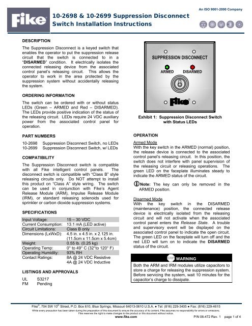
Exhibit 1: <strong>Suppression</strong> <strong>Disconnect</strong> <strong>Switch</strong><br />
with Status LEDs<br />
OPERATION<br />
Armed Mode<br />
With the key switch in the ARMED (normal) position,<br />
the release device is connected to the associated<br />
control panel’s releasing circuit. In this position, the<br />
switch does not interfere with panel supervision of<br />
the releasing circuit or releasing operations. The<br />
green LED on the faceplate illuminates steady to<br />
indicate the ARMED status of the circuit.<br />
Note: The key can only be removed in the<br />
ARMED position.<br />
Disarmed Mode<br />
With the key switch in the DISARMED<br />
(maintenance) position, the connected release<br />
device is electrically isolated from the releasing<br />
circuit and will not activate when the associated<br />
control panel enters the Release State. A trouble<br />
and supervisory event will be displayed on the<br />
associated control panel to indicate the open circuit.<br />
The green LED on the faceplate will turn off and the<br />
red LED will turn on to indicate the DISARMED<br />
status of the circuit.<br />
a WARNING<br />
Both the ARM and IRM modules utilize capacitors to<br />
store a charge for releasing the suppression system.<br />
Before servicing the system, wait 10 minutes for the<br />
capacitor’s charge to dissipate.<br />
While every precaution has been taken during the preparation of this document to ensure the accuracy of its content, Fike assumes no responsibility for errors or omissions.<br />
Fike reserves the right to make changes to the product or this document without notice.<br />
www.fike.com P/N <strong>06</strong>-<strong>472</strong> Rev. 1 page 1 of 4<br />
®
SAFETY NOTICES<br />
Read all of the following safety notices before<br />
attempting to install or use this device. Personal<br />
injury or accidental release of the suppression<br />
system may result if the following instructions are not<br />
followed.<br />
a WARNING<br />
1. The SHP, SHP-Pro, Rhino, and Intella-Scan<br />
control panels are equipped with an<br />
ARM/DISABLE switch for the releasing circuit(s).<br />
If using the Agent <strong>Disconnect</strong> switch with these<br />
panels, the ARM/DISABLE switch on the panel<br />
must be in the ARM position for the switch to<br />
operate properly. DO NOT use the<br />
ARM/DISABLE switch simultaneously with the<br />
Agent <strong>Disconnect</strong> switch.<br />
2. A manual actuator can also be used to fire the<br />
GCA’s connected to an ARM. It is extremely<br />
important to make sure the GCA is not<br />
connected to a manual actuator before<br />
considering the circuit “DISARMED”.<br />
I Caution<br />
1. Only release devices that are connected to the<br />
Agent <strong>Disconnect</strong> switch will be disconnected by<br />
the user operated key switch.<br />
2. The Agent <strong>Disconnect</strong> switch DOES NOT<br />
remove the firing charge stored in the ARM or<br />
IRM capacitors. It removes the charging current<br />
to the releasing circuit and allows time for the<br />
capacitors to de-energize until there is<br />
insufficient energy to activate the releasing<br />
device.<br />
SWITCH ASSEMBLY<br />
The disconnect switch is shipped unassembled and<br />
must be assembled in the field using the following<br />
instructions:<br />
1. Remove the switch components (faceplate and<br />
switch) from the shipping package.<br />
2. Remove the operator from the contact block by<br />
pulling up the locking lever and turning it to the<br />
left as shown in Exhibit 2.<br />
Pull up the locking lever. Pull out the contact block.<br />
Turn the lever to the left.<br />
Exhibit 2: Removing and Installing<br />
the Contact Block<br />
Note: <strong>Switch</strong> contacts will transfer to the<br />
ENABLED position when the operator is removed<br />
from contact block.<br />
3. Remove the locking ring from the operator and<br />
insert the operator into the switch faceplate from<br />
the front as shown in Exhibit 3. Reinstall the<br />
locking ring onto the operator from the back and<br />
tighten with pliers or locking ring wrench (02-<br />
12318), making sure that the TOP marking on<br />
the operator is aligned with the top center of the<br />
faceplate.<br />
Operator<br />
Face Plate<br />
Exhibit 3: Operator Installation<br />
Locking Ring<br />
4. Insert the operator into the contact block making<br />
sure that the Idec marking on the contact block<br />
is facing the same direction as the TOP marking<br />
on the operator. Turn the locking lever to the<br />
right.<br />
Fike ® , 704 SW 10 th Street, P.O. Box 610, Blue Springs, Missouri 64013-<strong>06</strong>10 U.S.A. ● Tel: (816) 229-3405 ● Fax: (816) 229-4615<br />
P/N <strong>06</strong>-<strong>472</strong> Rev. 1 page 2 of 4 www.fike.com
SWITCH INSTALLATION AND TESTING<br />
INSTRUCTIONS<br />
The <strong>Suppression</strong> <strong>Disconnect</strong> switch is installed into<br />
the releasing circuit between the associated control<br />
panel or releasing module and the releasing device<br />
itself.<br />
The following steps must be followed in order to<br />
properly install and test the operation of the agent<br />
disconnect switch. Failure to follow these steps<br />
could result in improper operation or accidental<br />
release of the suppression system.<br />
Installation and Testing Steps:<br />
1. <strong>Disconnect</strong> releasing circuit(s) from the host<br />
control panel or releasing module. If applicable,<br />
allow 7-10 minutes for capacitor charge on the<br />
ARM or IRM module(s) to dissipate.<br />
2. Disarm the suppression system following the<br />
recommended procedure for each type of<br />
releasing device (ARM/IRM). For releasing<br />
solenoids, disconnect the coil operator from the<br />
valve.<br />
a WARNING<br />
Failure to disconnect the releasing circuit(s) and<br />
disarm the releasing device(s) prior to<br />
installation of the switch may result in accidental<br />
discharge of the suppression system.<br />
Note: Refer to Fike documents <strong>06</strong>-1<strong>06</strong> and <strong>06</strong>-<br />
552 respectively for ARM and IRM disarming<br />
procedure.<br />
3. Select appropriate location for mounting switch<br />
and secure back-box to wall with suitable<br />
anchors.<br />
Back Box Options<br />
<strong>Switch</strong> without LEDs<br />
For surface mounting, use a two-gang masonry<br />
box (Raco 691 or equal) with a depth of 2.5”<br />
(6.35cm). For flush mounting, use a two-gang<br />
mud ring (raised ½” minimum) on a 4 in square x<br />
2-1/8” deep box.<br />
<strong>Switch</strong> with LEDs<br />
For surface mounting, use a two-gang masonry<br />
box (Raco 696 or equal) with a depth of 3.5”<br />
(8.89cm). For flush mounting, use a two-gang<br />
mud ring on a 4 in square x 3-1/2” deep box<br />
(Raco 256 or equal).<br />
4. Route conduit and field wiring (i.e., releasing<br />
circuit, auxiliary power and supervisory circuit)<br />
into back-box. Verify that wiring is free from<br />
ground fault or short-circuit conditions before<br />
proceeding.<br />
5. Connect field wiring to appropriate terminals on<br />
the switch contact block as shown in Exhibits 4<br />
and 5, making sure to observe circuit polarity.<br />
6. Reconnect releasing circuit(s) to the host control<br />
panel or releasing module. Do NOT reconnect<br />
releasing devices (i.e., ARM, IRM or Solenoids)<br />
at this time.<br />
7. Functionally test the operation of the disconnect<br />
switch in both the ARMED and DISARMED<br />
modes following the recommended procedure<br />
for each type of releasing device (ARM/IRM).<br />
Correct any problems before proceeding to next<br />
step.<br />
8. <strong>Disconnect</strong> releasing circuit(s) from the host<br />
control panel or releasing module and allow 7-10<br />
for capacitor charge on the ARM or IRM<br />
module(s) to dissipate if applicable.<br />
9. Attach the disconnect faceplate to the back-box<br />
with supplied mounting screws and turn key<br />
switch to DISARMED position.<br />
10. Rearm the suppression system(s) following the<br />
recommended procedure for each type of<br />
releasing device (ARM/IRM). For releasing<br />
solenoids, reconnect the releasing circuit to the<br />
control panel or releasing module.<br />
Note: Refer to Fike documents <strong>06</strong>-1<strong>06</strong> and <strong>06</strong>-<br />
552 respectively for ARM and IRM arming<br />
procedure.<br />
11. Turn the key switch to the ARMED position. The<br />
system is now operational.<br />
SPARE PARTS<br />
02-12294 Double contact block (2 NC)<br />
02-12295 Double contact block (2 NO)<br />
02-12296 Replacement keys<br />
02-12297 4 block switch<br />
02-12298 5 block switch<br />
02-12300 Single contact block (NO)<br />
02-12314 2 block switch<br />
02-12315 3 block switch<br />
02-12316 Single contact block (NC)<br />
02-12317 Double contact block (1 NC / 1 NO)<br />
02-12318 Locking ring wrench<br />
02-3013 Green LED<br />
02-3009 Red LED<br />
02-1553 2.2K, .5W, 5% resistor<br />
10-2714 Cover plate w/o LED holes<br />
10-2713 Cover plate with LED holes<br />
Fike ® , 704 SW 10 th Street, P.O. Box 610, Blue Springs, Missouri 64013-<strong>06</strong>10 U.S.A. ● Tel: (816) 229-3405 ● Fax: (816) 229-4615<br />
www.fike.com P/N <strong>06</strong>-<strong>472</strong> Rev. 1 page 3 of 4
SWITCH TERMINAL BLOCKS<br />
(BACKSIDE OF FACEPLATE)<br />
SUPERVISORY CIRCUIT<br />
FROM CONTROL PANEL<br />
OR ADDRESSABLE<br />
MONITOR MODULE<br />
RELEASE CIRCUIT FROM<br />
CONTROL PANEL OR<br />
-<br />
RELEASING MODULE<br />
+<br />
24 VDC<br />
(SEE NOTE 3)<br />
-<br />
+<br />
DISARMED<br />
R<br />
G<br />
ARMED<br />
SWITCH TERMINAL BLOCKS<br />
(BACKSIDE OF FACEPLATE)<br />
SUPERVISORY CIRCUIT<br />
FROM CONTROL PANEL<br />
OR ADDRESSABLE<br />
MONITOR MODULE<br />
RELEASE CIRCUIT FROM<br />
CONTROL PANEL OR<br />
-<br />
RELEASING MODULE<br />
+<br />
NO NC<br />
NOTES:<br />
1. WIRING DIAGRAM SHOWS SWITCH IN ARMED POSITION.<br />
2. ALL WIRING SHOWN IS SUPERVISED AND POWER LIMITED.<br />
NC NO NC<br />
NO NC<br />
NOTES:<br />
1. WIRING DIAGRAM SHOWS SWITCH IN ARMED POSITION.<br />
2. ALL WIRING SHOWN IS SUPERVISED AND POWER LIMITED.<br />
3. 24 VDC POWER TO SWITCH LEDs SHALL COME FROM THE<br />
ASSOCIATED CONTROL PANEL OR FROM A BATTERY<br />
BACKED 24 VDC, REGULATED, POWER-LIMITED POWER<br />
SUPPLY LISTED FOR FIRE PROTECTIVE SIGNALING USE.<br />
Exhibit 5: Wiring Diagram of <strong>Switch</strong> with LEDs<br />
Fike ® , 704 SW 10 th Street, P.O. Box 610, Blue Springs, Missouri 64013-<strong>06</strong>10 U.S.A. ● Tel: (816) 229-3405 ● Fax: (816) 229-4615<br />
P/N <strong>06</strong>-<strong>472</strong> Rev. 1 page 4 of 4 www.fike.com<br />
NC<br />
TO NEXT DISCONNECT<br />
SWITCH OR END-OF-LINE<br />
RESISTOR<br />
Exhibit 4: Wiring Diagram of <strong>Switch</strong> without LEDs<br />
-<br />
+<br />
TO ARM, IRM OR<br />
RELEASING SOLENOID<br />
-<br />
+<br />
TO NEXT DISCONNECT<br />
SWITCH OR END-OF-LINE<br />
RESISTOR<br />
TO ARM, IRM OR<br />
RELEASING SOLENOID