Hydra-70 Rocket System Integration Information DESCRIPTIONS ...
Hydra-70 Rocket System Integration Information DESCRIPTIONS ...
Hydra-70 Rocket System Integration Information DESCRIPTIONS ...

Create successful ePaper yourself
Turn your PDF publications into a flip-book with our unique Google optimized e-Paper software.
<strong>DESCRIPTIONS</strong><br />
<strong>Hydra</strong>-<strong>70</strong> <strong>Rocket</strong> <strong>System</strong><br />
<strong>Integration</strong> <strong>Information</strong><br />
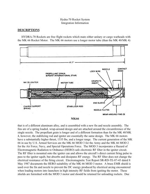
HYDRA-<strong>70</strong> <strong>Rocket</strong>s are free flight rockets which mate either unitary or cargo warheads with<br />
the MK 66 <strong>Rocket</strong> Motor. The MK 66 motors use a longer motor tube (than the MK 40/MK 4)<br />
MK66<br />
that is of a different aluminum alloy, and is assembled with a new fin and nozzle assembly. The<br />
fins are of a spring loaded, wrap-around design and are attached around the circumference of the<br />
single nozzle. The propellant grain is longer and of a different formation than for the MK 40/MK<br />
4, however, the stabilizing rod and igniter are essentially the same design. The MK 66 motors<br />
have a substantially higher thrust, 1335 lbs, and a longer range. The current generation of the MK<br />
66 in use by U.S. Armed Services are the MK 66 MOD 3 for the Army and the MK 66 MOD 2<br />
for the Air Force, Navy, and Special Operations Force. The MOD 3 incorporates a Hazard of<br />
Electromagnetic Radiation to Ordnance (HERO) safe electronic RF filter in the igniter circuit.<br />
The RF filter is mounted onto the igniter can and allows the aircraft’s direct current firing pulse to<br />
pass to the igniter squib, but absorbs and dissipates RF energy. The RF filter does not change the<br />
electrical resistance of the firing circuit. Electromagnetic Test Report SR-RD-TE-87-43 dated 8<br />
May 1987 documents the HERO suitability of the MK 66 MOD 3 motor. A brass EMR shield is<br />
used over the fin and nozzle to prevent the DC energy produced by electrical arcing encountered<br />
when loading motors into launchers in high intensity RF fields from igniting the motor. These<br />
shields are furnished with the MOD 3 motor and should be retained for unloading rockets. Due
to the shipboard concern of Foreign Object Damage (FOD), the other Armed Services use the<br />
MOD 2 motor. The MOD 2 contains a Dahlgren Bridge Assembly (DBA) for a HERO filter.<br />
The DBA is a wheatstone bridge designed to prevent the RF of concern from igniting the motor.<br />
It consists of two stainless steel wires and two copper core, stainless clad wires of proper<br />
resistance crimped together. The alternating current induced by the RF is shunted around the<br />
igniter squib. The MOD 2 motor uses a stabilizing rod that is hollow core that acts as a conduit<br />
for the igniter wires. The DBA increases the resistance of the motor from 0.7 - 2.0 ohms to 2.3 -<br />
3.0 ohms. This additional resistance can cause the fielded aircraft fire control to err during<br />
inventory of available rockets.<br />
The MOD 4 motor is a new design that will become common to all Armed Services and<br />
eliminates the undesirable traits of the previous designs. The first deliveries of the MOD 4 motor<br />
will be in 1998. The purpose of the MK 66 MOD 4 <strong>Rocket</strong> Motor is to improve several safety<br />
(specifically E 3 ) deficiencies of the MK 66 MOD 2 <strong>Rocket</strong> Motor. The MOD 4 motor<br />
incorporates a new initiator (MK 26 MOD 0), igniter (MK 311 MOD 0), and E 3 filtering.<br />
As a result, the MK 66 MOD 4 <strong>Rocket</strong> Motor is HERO, 300 KV and 25 KV ESD, and EMP<br />
safe. The E 3 filtering includes a capacitor under the nozzle and two low pass filters located on the<br />
igniter and in the initiator. Also, a natural spark gap also exists between the contact band and<br />
nozzle body. The bare MK 66 MOD 4 <strong>Rocket</strong> Motor does not function when exposed to<br />
300,000 volts of Electrostatic Discharge (ESD). During testing, as a worst case test, the U.S.<br />
Government forced the charge from the 300 KV ESD to hit the rocket motor contact band (firing<br />
contact). The filters reliably diverted the ESD pulse away from the initiator. The MK 26 MOD 0<br />
Initiator, the MK 311 MOD 0 Igniter, and the MK 66 MOD 4 <strong>Rocket</strong> Motor pass 25 KV ESD<br />
(human generated electrostatic discharge). The MK 66 MOD 4 <strong>Rocket</strong> passed HERO testing<br />
using the Apache and Blackhawk helicopters as the test platforms. These helicopters are<br />
considered to present the worst case for HERO testing. HERO safe certification exists in letter<br />
DD/NSWC 8020 F52-RDD dated 13 April, 1995. EMP analyses on the MK 66 MOD 4 <strong>Rocket</strong><br />
Motor shows it has an EMP factor of safety of over 35 million. This is because the EMP pulse is<br />
extremely short (3 microseconds). The short pulse does not provide enough energy to heat the<br />
MK 26 MOD 0 Initiator bridgewire.<br />
Tabulated data:<br />
Weight, shipped: 13.6 lb<br />
Burn time: 1.05 - 1.10 sec<br />
Average thrust (77 o F): 1300 - 13<strong>70</strong> lb<br />
Impulse (77 o F): 1472 lb/sec<br />
Motor burnout range: 1300 ft (397 m)<br />
Motor burnout velocity: 2425 fps<br />
Launch spin rate: 10 rps<br />
Velocity at launcher exit: 148 fps<br />
Acceleration: 60-<strong>70</strong> G (initial),<br />
95-100 G (final)<br />
Range, max @ QE 43 o<br />
w/ MPSM whd: 11,407 yd (10,426 m)<br />
Igniter resistance: 0.7 - 2.0 ohms<br />
Propellant Type: Extruded double base,<br />
ethylcellulose inhibited,<br />
cartridge loaded<br />
Propellant Weight: 7 lb<br />
Propellant Configuration: 8-point internal<br />
burning star<br />
Temperature Limits:<br />
Storage: -65 o F to +165 o F<br />
(-53.35 o C to +73.15 o C)<br />
Operation: -50 o F to +150 o F<br />
(-45 o C to +64.9 o C)
M151 Warhead<br />
M229 Warhead<br />
Both the M151 and M229 use the M423 Fuze, making them High Explosive Point Detonating<br />
(HEPD) warheads. The M151 uses 2.3 pounds of composition B-4 High Explosive. The 10<br />
pound warhead gains lethality from the nose section which is fabricated using nodular, pearlitic<br />
malleable, or ferritic malleable cast iron. The 17 pound M229 uses 4.8 pounds of composition B-<br />
4 High Explosive. The performance of the M229 is roughly a 50 percent increase in lethal area<br />
over the M151. Temperature limits for storage and firing the M151 and M229 are -65 o F to +150<br />
o F (-53.35 o C to +64.9 o C).<br />
The M423 Fuze consists of four major assemblies: firing pin and body assembly; fuze body;<br />
safe and arming (S&A) device; and the booster assembly. The S&A device consists of a rotor<br />
housing assembly and unbalanced rotor assembly, an escapement assembly and set-back weight.<br />
The unbalanced rotor assembly houses the primer and detonator and is maintained in the unarmed<br />
(out-of-line) position. When the rocket motor is fired, sustained acceleration permits the set-back<br />
(inertial mass) weight to move rearward, releasing the unbalanced rotor, which in rotating drives<br />
the escapement and gear assembly to the armed position. The rotor reaches the armed (in line)<br />
position when the rocket has traveled 43 to 93 meters and then is locked into the armed position<br />
by a spring-loaded pin. The rotor will return to the unarmed position if the minimum rocket<br />
energy (product of acceleration and time) is not sensed throughout the arming distance. Upon<br />
impact, the firing pin body walls are crushed between the target and the oncoming fuze body. The
firing pin contained in the firing pin body then impacts the oncoming S&A mechanism within the<br />
fuze body, initiating the explosive train. The explosive consists of the M104 primer, M85<br />
detonator, lead, booster and warhead explosive which are initiated in sequential order. The M423<br />
is used for launch from low speed aircraft. The M427 is a variation used for launch from high<br />
speed aircraft and requires 180 to 426 meters rocket travel to arm. The PD fuzes do not require<br />
an umbilical connection to the launcher.<br />
Tabulated data:<br />
M151 HEPD <strong>Rocket</strong> w/ MK 66 MOD 3 Motor<br />
NSN:1340-01-269-9123<br />
DODIC: H583<br />
Hazard Classification: Quantity-Distance Class 1.1, Storage Compatibility Group E<br />
UNO Serial No. 0181<br />
DOT Label "Explosive 1.1E", Proper Shipping Name "<strong>Rocket</strong>s"<br />
M151 Warhead w/ M427<br />
NSN: 1340-00-725-8382<br />
DODIC: H842.<br />
M229 HEPD <strong>Rocket</strong> w/ MK 66 MOD 2 Motor<br />
NSN: 1340-01-309-8300<br />
DODIC: H642<br />
Hazard Classification: Quantity-Distance Class 1.1, Storage Compatibility Group E<br />
UNO Serial No. 0181<br />
DOT Label "Explosive 1.1E", Proper Shipping Name "<strong>Rocket</strong>s with Bursting Charge".<br />
The M261 Warhead is a cargo warhead consisting of a nose cone assembly, a warhead case,<br />
an integral fuze, 9 submunitions, and an expulsion charge assembly. The nose cone assembly, a<br />
plastic cone bonded to a metal cup-shaped base, is attached to the body by shear pins. The body<br />
is a hollow cylinder loaded with 9 full caliber multipurpose submunitions (MPSM). Each<br />
submunition has a Ram Air Decelerator (RAD), folded, which nests into the shaped charge cone<br />
of the submunition ahead; the 9th (forward) submunition nests into the forward cup which makes<br />
up the base of the nose cone. A metal pusher plate is located just aft of the submunition cargo<br />
stack and is forward of the expulsion charge assembly. The threaded end of the body is machined<br />
internally to accommodate a base detonating, remote settable, variable range fuze. The 9 High<br />
Explosive (HE) submunitions are deployed by initiation of a 5.5 gram expulsion charge, consisting<br />
of 80% M10 double base propellant and 20% Class 6 black powder. The expulsion charge is<br />
initiated by an M84 electric detonator contained in the M439 fuze. A pusher plate then ejects the<br />
stack of submunitions through the nose cone.<br />
The primary cargo warhead fuze is the M439 Fuze. It is a resistance-capacitance electronic<br />
variable time delay fuze. The time delay is remotely set for the desired functioning distance (time)<br />
by charging the circuit from the fire control center, providing a variable range of 0.5 to 7.2<br />
kilometers. The fuze does not have an internal battery; instead energy is supplied from by the<br />
aircraft setter at the time of fuze setting. The energy is stored in a capacitor and will operate the<br />
electronic timer and fire the M84 electronic detonator. The charging cycle takes place<br />
approximately 50 milliseconds prior to rocket motor firing. The fuze begins timing at the first<br />
motion of the rocket and will function at the prescribed time if the Safety and Arming (S&A)
device is armed. The S&A mechanism also prevents the fuze from being charged if it is in the<br />
partially-armed or fully-armed position. The S&A is a mechanical acceleration integrator with an<br />
unbalanced rotor holding the M84 electric detonator and a runaway escapement. An acceleration<br />
greater than 27G is necessary to arm the fuze. The M439 Fuze is a base mounted, forward firing<br />
fuze. The fuze connector cable extends from the fuze, through the warhead in a lengthwise<br />
channel, and exits the ogive for connection to the launcher by an umbilical connector.<br />
The HE, MPSM M73 Grenade consists of a steel body with a fragmenting wall filled with<br />
Composition B explosive incorporating a shaped charge liner, LX14 booster, explosive lead<br />
charge, M230 omnidirectional fuze with M55 detonator, wave shaper, and fabric drag device<br />
(RAD). The fragmenting body produces 10 grain fragments with a maximum velocity of<br />
approximately 5,000 feet per second. The shaped charge sprays lethal fragments nearly horizontal<br />
360 degrees. The submunitions consistently impact within a 40-meter radius of each other.<br />
Submunition self destruct has not been a consideration. EOD procedures obviate the need for self<br />
destruct. Lethality (penetration) is classified and can be made available through licensed<br />
agreement. The performance is roughly a <strong>70</strong> percent (SMCAR-CCH-A Memorandum, 23 Jun<br />
1988) increase in lethal area over the M151.<br />
Tabulated data:<br />
M261 MPSM <strong>Rocket</strong> w/ MK 66 MOD 3 Motor
NSN: 1340-01-269-1447<br />
DODIC: H165<br />
Hazard Classification: Quantity-Distance Class 1.2, Storage Compatibility Group E<br />
UNO Serial No. 0182<br />
DOT Label "Explosive 1.2E", Proper Shipping Name "<strong>Rocket</strong>s".<br />
Temperature Limits:<br />
Firing: -50 o F to +150 o F<br />
Storage: -50 o F to +160 o F<br />
The M255A1 Flechette Warhead is intended to be used against light material and personnel<br />
targets. The warhead is also a cargo warhead, using the M439 Fuze, and functionally equivalent<br />
to the M261 cargo warhead. At expulsion, 1,179 flechettes separate and form a disk-like mass<br />
which breaks up with each flechette assuming an independent trajectory, forming a repeatable<br />
dispersion pattern. The flechette uses kinetic energy derived from the velocity of the rocket to<br />
produce the desired impact and penetration effect on the target.<br />
Tabulated data:<br />
M255A1 Flechette w/ MK 66 MOD 2 Motor<br />
NSN: 1340-01-309-5799<br />
DODIC: H462<br />
Flechette: 60 grain, steel, phosphate coated<br />
Hazard Classification: Quantity-Distance Class 1.4, Storage Compatibility Group G<br />
UNO Serial No. 0191<br />
DOT Label "Explosive 1.4G", Proper Shipping Name <strong>Rocket</strong>s"
The M264 RP Smoke is also a cargo warhead. The warhead is used as a red phosphorus (RP)<br />
filled smoke rocket propelled by the MK 66 motor and functions at a remote settable range from<br />
1000 to 6000 meters. Upon functioning, the M439 Fuze ignites the expulsion mix which<br />
simultaneously ignites and ejects the 5 pound RP payload through the shear-pinned nose cone.<br />
The burning RP drops to the ground producing a voluminous cloud of white smoke. Fourteen<br />
M264 rockets will screen a 300-400 meter front with a 5-10 knot wind from the unaided eye for a<br />
minimum of 5 minutes. The RP pellet stack assembly consists of 72 RP pellets arranged in 18<br />
rows of 4 each and are separated by felt pieces impregnated with a phosphine gas adsorbent<br />
mixture, manganese dioxide/cuprous oxide.<br />
Tabulated data:<br />
M264 RP Smoke w/ MK 66 MOD 3 Motor<br />
NSN: 1340-01-289-4719<br />
DODIC: H184<br />
RP: JXS-10 Smoke Composition Pellets, 0.035 kg/wedge (31.5 gms)<br />
Hazard Classification: Quantity-Distance Class 1.4, Storage Compatibility Group G<br />
UNO Serial No.<br />
DOT Label "Explosive 1.4G", Proper Shipping Name <strong>Rocket</strong>s"
The M257 illuminating warhead consists of an ignition system, flare, main parachute, drogue<br />
parachute assembly, and an integral fuze and delay assembly. The warhead is enclosed in an<br />
aluminum case. The setback-actuated fixed time integral fuze provides a standoff distance of<br />
approximately 3,000 meters. The arming fuze and delay assembly is actuated by motor<br />
acceleration. The rocket is fired from the helicopter to attain elevation between 2000 and 4000<br />
feet at 3000 meters downrange. The M257 candle descends at 15 feet per second, burns for<br />
approximately 100 seconds with a minimum light output of one million candle power.<br />
Except for the illuminent, the M278 is identical to the M257 warhead. At the aft end of the<br />
Separation and Drogue Assembly is the Motor Adapter which is the threaded interface for the<br />
launch rocket motor. Inside the adapter is the M442 fuze which initiates the firing sequence for<br />
the M278 flare. The fuze must sense an acceleration of at least 17-22 G for about 1 second prior<br />
to arming. Upon deceleration of the burnt-out rocket motor the armed fuze fires, directing its<br />
output into a 9-second pyrotechnic delay column which in turn ignites a separation charge. The<br />
separation charge produces a rapid increase in pressure inside the motor adapter which is reacted<br />
by a pusher plate on top of the Drogue Housing. This shears 12 holding pins that are evenly<br />
spaced around the circumference of the joint. The pressure also provides an accelerating force for<br />
the flare and a decelerating force for the launching rocket motor with the Motor Adapter<br />
attached. This ensures positive separation for the flare, and a Deflector plate pulls the expended<br />
motor out of the flare flight path. When the Pusher Plate falls into the airstream it pulls the<br />
Drogue Chute out of the aft end of the Drogue Housing. Attached to the shroud line bridle of the<br />
Drogue Chute is a nylon cord which is attached to the Pull Wire “Quickmatch” of a 2-second<br />
delay “Gas Generator.” The Quickmatch ignites the delay, which in turn fires a Secondary<br />
Expulsion charge. This charge functions as the first, producing pressure that shears another set of<br />
12 pins, evenly spaced around the circumference of the flare. Once again the pressure provides an<br />
acceleration/deceleration force to the Drogue Housing and the Candle & Parachute Assembly.
Attached to the Pusher Plate is the cord for the Pilot Chute. As the Pilot Chute deploys, it pulls<br />
the Main Chute assembly out of its housing (Parachute Insert) for Main Chute deployment.<br />
Attached to the Main Chute support cable is a Lanyard that runs through an internal raceway in<br />
the Candle and is attached to the Slider assembly in the Igniter assembly. As the main chute is<br />
deployed, it pulls the Lanyard with a minimum force of 40 pounds. This force shears a shear pin<br />
and moves the slider assembly into the firing position, cocks and releases the firing hammer and<br />
fires the ignition primer. During launch of the <strong>Rocket</strong>, acceleration forces of at least 17 G for<br />
duration of approximately one second withdrew the weight assembly of the “Zig-Zag” ignition<br />
safe/arm mechanism from its saving position in the slider assembly, allowing Slider movement.<br />
The output of the ignition primer is directed into a cavity containing boron pellets. The fire from<br />
the boron pellets is directed on the forward face of the flare’s illuminant Candle and also on a<br />
small propellant wafer which acts as an ignition booster. The Candle produces light in the near IR<br />
spectrum for about 180 seconds. The main parachute allows for a descent rate of approximately<br />
13 feet per second.<br />
Tabulated data:<br />
M257 Illumination Flare w/ M442 Fuze<br />
Operating temperature limits: -25 o F to +140 o F<br />
(-31.35 o C to +59.40 o C)<br />
Candle composition: Magnesium Sodium Nitrate<br />
Candle weight: 5.44 lb (2.47 kg)<br />
Illumination intensity, visible: 817.19 CP (avg.)<br />
infrared: 250.02 watts/sr (avg.)<br />
Illumination duration: 197.38 sec (avg.)<br />
Function time: 14.23 sec (avg.)<br />
Shipping and storage data:<br />
Storage class/SCG: 1.2 G<br />
DOT shipping class: A<br />
DOT designation: <strong>Rocket</strong> Ammunition with Illuminating Projectile<br />
Field Storage: Group D<br />
NSN: 1340-01-268-7175<br />
DODIC: H183<br />
UNO Serial No.<br />
M278 IR Flare w/ M442 Fuze<br />
NSN:<br />
DODIC: H154<br />
UNO Serial No.
The U.S. Army Lightweight Launchers (LWL) are the M260, 7-tube and the M261, 19-tube<br />
launchers. The aluminum launchers are inexpensive enough to be disposable, yet durable enough<br />
to be reused after as many as 32 firings. The weight savings over the previous Army launchers<br />
allows the Army to add other features to the aircraft's rocket system for improved performance.<br />
The launcher permits fuze-timing selection from the cockpit and will launch rockets using either<br />
the MK 40 or the MK 66 motors. The aft end of each tube in the launcher is fitted with a<br />
pivoting igniter arm which imparts the ignition current from the firing switch to the rocket motor.<br />
A side contact is lowered inside the launch tube for MK 66 ignition with the actuation of the<br />
pivoting arm. When the rocket is fired, the igniter arm is pushed back and a mechanical link<br />
assists in releasing the rocket from the rocket retainer. However, the primary mode of release is<br />
rocket override of the retainer in the launcher. The rocket retention force is specified to be<br />
between 1<strong>70</strong> and 600 pounds, easily overridden by the rocket thrust of over 1300 pounds.<br />
Weight saving was achieved for the LWL design by minimizing the use of rivets, welding and<br />
adhesive. Instead, the launchers are assembled using electromagnetic force to swage the<br />
aluminum skin and tubes around the four bulkheads. The center two bulkheads are welded to the<br />
aluminum strongback. This strongback establishes the rigidity of the launcher and is designed in<br />
accordance with MIL-A-8591 for interface with aviation suspension racks and sway braces. The<br />
19-tube launcher has since been redesigned to implement a floating solid bulkhead at the front of<br />
the launcher. This solid bulkhead was necessary to minimize the warping from heat built up<br />
during ripple launches. All other bulkheads are a laminated stack of plates. The front bulkhead of<br />
the 7-tube launcher continues to use a laminated stack.<br />
Electrical connectors are referred to as J1 and J2 connectors. The J1 connector (P/N<br />
13048761 is a 26-pin connector for the motor ignition circuit and the J2 (P/N 13048762) is a 23pin<br />
connector for the fuze setting circuit. The firing interval that the launcher normally<br />
experiences from the fire control is 0.06 seconds.
Environmental Protection Devices (EPD) have been designed to protect loaded launchers in<br />
flight from collecting ice and debris which can cause a rocket to stick in the tube, a condition that<br />
can result in a hangfire. The EPDs are molded from an ABS plastic in one piece and mount to the<br />
face of the launcher with captive bolts. The EPD effectively protects each tube with a dome<br />
cover that is grooved on the surface for fragmentation upon rocket exit. Fragments are designed<br />
to not exceed one square inch and can be ingested without event by the turbine engines of the<br />
Apache helicopter. A side benefit of the EPD is the thermal protection for the launcher face to<br />
prevent warping, which eventually will lead to erosion of the launcher tubes. This also will<br />
minimize the heat signature of the launcher after rocket firings.<br />
RMS Display Unit RMS Operations Unit<br />
The M138 <strong>Rocket</strong> Management Subsystem (RMS) is a pilot-operated subsystem that<br />
interfaces with the wing stores subsystem in the helicopter. The RMS operates from power<br />
supplied by the aircraft and consists of one Display Unit and four Operations Units. The RMS<br />
enables the aircraft pilot to select and launch MK 40 or MK 66 rocket motors with the desired<br />
warhead/fuze combination from two or four 7- or 19-tube launchers mounted under the aircraft<br />
stub wings. The RMS automatically senses the quantity and type of launcher installed and<br />
automatically sets its firing sequence to agree with the tube numbering of the launcher on board.<br />
Should one or more launchers be disabled, the RMS will cause the corresponding launcher on the<br />
opposite side of the fuselage to become inactive to maintain in-flight stability by equalizing the<br />
load of unfired rockets.<br />
<strong>Rocket</strong>s are loaded according to type (warhead/fuze) in up to five loading zones, and the types<br />
loaded in each zone are indicated by manually setting five 12-position thumb wheel switches on<br />
the Display Unit panel. The switch positions are marked with two- or three-letter descriptors that<br />
represent the available warhead/fuze configurations. When power is applied to the RMS, it<br />
automatically inventories the rounds loaded in each zone and provides the pilot with a numeric<br />
display of the quantities available for launching from each zone. By setting switches on the face<br />
of the Display Unit, the pilot can select the rocket types to be launched, set the fuzes according to<br />
the tactical situation, and determine the quantities of rockets to be launched in each volley.<br />
<strong>Rocket</strong>s are then launched when the pilot or copilot/gunner squeezes the trigger switch on the<br />
cyclic stick. Should the trigger switch be released before the entire volley has been launched, the<br />
numeric display on the face of the Display Unit is immediately updated to continuously reflect the
quantities of rockets remaining in each loading zone. Refer to TM 9-1090-207-13&P for<br />
additional information pertaining to RMS components.<br />
The primary objectives of the remotely settable fuze concept were to use very inexpensive<br />
components in the fuze itself, eliminate any battery required to run the electronics during the fuze<br />
run time, and accomplish the accuracy goals throughout the total environmental range. The<br />
solution was to select a resistance-capacitance technique wherein relatively inexpensive, broadtolerance<br />
(+/- 20 percent) components could be used for high-volume production of relatively<br />
inexpensive electronic fuzes. To accurately set the capacitance-charged fuzes for the desired run<br />
time throughout the environmental range requires a compensating setter located in the aircraft.<br />
The setter, immediately prior to launching a rocket, determines the amount of energy required by<br />
the fuze timing capacitor for the component variations existing along with temperature effects to<br />
run the fuze timing circuitry for the range selected. The setter then charges the timing capacitor<br />
and the storage capacitor used as both the power source to run the electronics and the power<br />
source to initiate the pyrotechnic train through initiation of the electric detonator in the fuze<br />
safeing and arming device. The setter must be capable of compensating for 20 percent variations<br />
in component value and for variations in fuze run time due to temperature effects on individual<br />
fuzes. Since each fuze is unique, each fuze must receive a different amount of energy in its timing<br />
sequence, whether it be singles, pairs, or quads, fuzes must therefore receive different amounts of<br />
energy to accomplish the same set time. Therefore, just prior to firing, the individual fuze and its<br />
setter compose an integral subsystem which must perform its function accurately across the entire<br />
environmental spectrum, compensating for inherent errors in individual fuzes.<br />
The Display Unit is a cockpit-mounted line-replaceable unit that presents the pilot with<br />
controls and displays for inventorying and controlling the launching of aerial rockets. It also<br />
contains the power supply and other common circuits necessary for the RMS components to<br />
operate as a subsystem. The Display Unit transmits the electrical command signals selected by the<br />
pilot to the Operations Units. One Operations Unit is used for each launcher and contains the<br />
circuitry that sets the fuzes and the circuitry that provides the rocket motor squib firing pulses for<br />
the rockets loaded into the associated launcher.<br />
Additional description of the RMS is contained in enclosure 1. This is an early system<br />
description as taken from material used for training (extraneous pages have been extracted) of<br />
what eventually became the M138 RMS. It was originally fitted into the AH-1S model of the<br />
Cobra helicopter. The weight of the display unit is 6 pounds and of the operations unit is 2<br />
pounds each. The NSN for the M138 RMS is 1090-01-077-8939. A variation of this system<br />
known as the Armament Management <strong>System</strong> was fitted into the AH-1G model of the Cobra<br />
helicopter. It uses two zones and was intended as an interim solution for an eventual upgrade to<br />
the M138 RMS.
1. MECHANICAL.<br />
1.1 & 1.2 Physical Characteristics of the rocket system. The lengths, weights, centers of gravity<br />
and moments of inertia of the various rockets (MK 66) as measured are as follows:<br />
The length of the M261 LWL was previously defined as 66.190" (max). The weight, CG and<br />
moments for the M261 LWL are as follows:<br />
MK66 Motor<br />
only<br />
M151<br />
HE/M423 PD<br />
w/ MK66<br />
M229<br />
HE/M423 PD<br />
w/ MK66<br />
M261<br />
MPSM/M439<br />
w/ MK66<br />
M255A1/M439<br />
w/ MK66<br />
M257/M442<br />
w/ MK66<br />
M264/M439<br />
w/ MK66<br />
M261 Lightweight<br />
Launcher<br />
Empty Loaded<br />
Weight (lbs.) 82 596<br />
CG aft of nose (in.) 35.8 28.3<br />
CG above center line (in.) 0.78 0.14<br />
CG left of center line (in.) 0.033 0.004<br />
Pitch moment (slug-ft 2 ) 7.12 54.37<br />
Yaw moment (slug-ft 2 ) 7.28 54.52<br />
Roll moment (slug-ft 2 ) 0.629 3.37<br />
Weight, lbs CG from base Moments of Inertia, lb-in 2<br />
<strong>Rocket</strong> Length (inches) Live Fired<br />
Warhead Live Fired (inches) Live Fired Axial Transverse Axial Transverse<br />
---- 13.65 6.43 41.750 18.89 15.<strong>70</strong> 15.80 2032 9.30 1371<br />
9.30 22.95 15.73 55.125 29.96 33.55 26.20 6248 19.<strong>70</strong> 5008<br />
16.87 30.43 23.19 65.240 36.55 41.20 37.60 10479 29.60 7840<br />
13.50 27.15 19.93 66.100 35.26 40.02 29.40 9868 23.30 7595<br />
13.87 27.51 20.34 66.100 35.36 40.00 28.80 9848 22.10 7529<br />
10.57 24.22 17.00 <strong>70</strong>.400 34.75 40.04 27.60 10607 21.<strong>70</strong> 8383<br />
8.00 21.65 14.43 66.100 30.84 35.11 23.<strong>70</strong> 7639 17.00 6209<br />
Physical Characteristics of <strong>Rocket</strong>s
The centers of gravity for the M261 LWL when fully loaded with the following rockets are as<br />
follows:<br />
Configuration CG (in. from front) Weight (lbs.)<br />
Empty 35.8 82.0<br />
M151/M423/MK 66 33.1 518<br />
M229/M423/MK 66 27.2 660<br />
M257/M442/MK 66 29.0 542<br />
M264/M439/MK 66 32.4 493<br />
M261/M439/MK 66 28.5 598<br />
M255A1/M439/MK 66 28.4 604<br />
1.3 Aerodynamic data of the M261. Please refer to excerpts of MIL-A-8591 at enclosure 2 for<br />
calculation and modeling methods for aerodynamic loads. An example calculation performed by<br />
Hughes Aircraft, the designer of the LWL, is attached at the back of the enclosure. Airflow<br />
information would be unique to the aircraft platform and should be available from the U.S. Army<br />
Aviation and Troop Support Command (ATCOM).<br />
1.4 Qualification standards. Specifications which control the acceptance of rockets are listed in<br />
the chart below. The specification for the LWL is MIS-34583. The RMS is per enclosure 3.
1.5 Environmental influence to the helicopter. The MK 66 motor can eject the ignition wire upon<br />
launch. On more rare occasions, the MK 66 MOD 2 motor can eject the stabilizing rod upon<br />
launch. Observance of this occurrence indicates that approximately 50 percent are just after the<br />
rocket has left the launcher. The MK 66 MOD 4 motor has a more robust design for the<br />
stabilizing rod that should preclude ejection.<br />
Chemical and thermal effects are taken from IHSP 89-289. Theoretical combustion products<br />
appear in Table IV of this document and is shown below. The exhaust-induced pressure<br />
experienced in each launcher tube is 318 psi, measured near the aft end of the launcher.<br />
2. ELECTRICAL.<br />
2.1 Electrical Interface. The LWL electrical continuity shall be as specified in drawing 13048860<br />
for the M261 launcher (Type II launcher). When a device that selectively simulates the electrical<br />
characteristics of an electrically shorted motor of either the MK 40 or MK 66 type is loaded in a<br />
launcher tube, the total circuit resistance from that launch tube connector pin in connector J1 to<br />
the ground pin in the J1 connector shall not exceed 1 ohm with an applied current of not less than<br />
1 milliampere or not more than <strong>70</strong>0 milliamperes. Resistance will be tested with both the MK 40<br />
and MK 66 motors. The resistance of the electrical circuits between J2 and P, and J2 and ground<br />
shall not exceed 0.20 ohm with an applied current of not greater than <strong>70</strong>0 milliamperes. The<br />
insulation resistance between isolated circuits and ground shall be equal to or greater than<br />
500,000 ohms at 500 volts direct current (Vdc). With the negative return connected to pin Z of<br />
connector P, application of the system fuzing signal from the RMS to pins A through V of<br />
connector J2 shall supply fuze set voltage to rockets loaded in tubes 1 through 19 respectively.<br />
With the negative return of ignition circuit connected to pin Y and/or Z of connector J1, the
application of a fire signal of a minimum of 1 ampere for a minimum of 10 milliseconds from the<br />
RMS to pins A through V of connector J1 shall supply ignition voltage to rockets loaded in tubes<br />
1 through 19 respectively.
2.2 Description of the functional sequences. The pilot dials in the rocket type and quantity to be<br />
fired on the RMS. The RMS designates this data to the Fire Control Computer (FCC) of the<br />
aircraft, and the FCC selects the trajectory<br />
data from memory. The electronic fuze setter<br />
in the RMS will set the fuze when the pilot<br />
depresses the firing trigger. The gunner in the<br />
front seat of the Cobra sights in on the target<br />
through the telescopic sight unit and lases to<br />
obtain constantly updated range data. The<br />
aircraft FCC processes this data along with<br />
aircraft speed, relative wind, temperature and<br />
flight characteristics of the rocket, and<br />
computes the point at which the fuze must<br />
function for the intended target. The<br />
computer then presents a solution reticle<br />
through the heads up display (HUD) to the<br />
pilot in the back seat. The pilot must match the solution reticle to the boresight reticle on the<br />
HUD by maneuvering the aircraft and firing the weapon system. The computer continues to<br />
constantly update the solutions as the aircraft moves along. The pilot pitches the aircraft up,<br />
aligns the boresight reticle with the solution reticle and depresses the firing trigger. The fuze
eceives the latest ranging data about 50 milliseconds prior to the<br />
rocket motor being fired. The following is a listing of Field Manuals<br />
used in the employment of rockets:<br />
Explosives and Demolitions FM 5-25<br />
Ordnance General and Depot Support Services FM 9-4<br />
Ordnance Ammunition Service FM 9-6<br />
Attack Helicopter Gunnery FM 17-40<br />
Attack Helicopter Operations FM 17-50<br />
2.3 Power consumption. The rocket management system requires<br />
24-28 VDC.<br />
2.4 EMI. Aeronautical Design Standard (ADS) 37, Subject:<br />
Electromagnetic Environmental Effects (E 3 ) Management, Design, and Test Requirements and<br />
SARD-DO Memorandum, Subject: Army Acquisition Executive Policy Memorandum 91-3, Army<br />
Electromagnetic Environmental Effects (E 3 ) Program Implementation establish design<br />
requirements. As stated previously, the MK 66 MOD 4 <strong>Rocket</strong> Motor is HERO, 300 KV and 25<br />
KV ESD, and EMP safe. Warheads such as the M278 contain no electronic components and<br />
therefore do not present any E 3 concerns. The M255A1 and M264 warheads are recent<br />
developments and were evaluated for E 3 because both contain electrical/electronic components,<br />
specifically the M439 electronic fuze as well as the M84 electric detonator, and therefore do have<br />
the potential to be affected by E 3 . Naval Surface Weapons Center (H22-BF/RFM) Letter, dated<br />
22 Jan 87, Subject: Hazards of Electromagnetic Radiation to Ordnance Test Report of the <strong>Rocket</strong><br />
Management <strong>System</strong> showed that the M439 Fuze is “HERO SAFE ORDNANCE” and will not be<br />
affected by the HERO environment during presence, handling and loading. The M439 Fuze was<br />
tested for Electrostatic Discharge (ESD) susceptibility with an inert warhead and found to be<br />
sufficiently hardened to personnel-borne ESD. As a result, there are no E 3 concerns associated<br />
with either warhead/fuze combination. While documentation does not exist for older designs,<br />
similar results can be expected for warheads fuzed with the M439 Fuze. A fact to consider is that<br />
the M439 Fuze is inherently shielded by the warhead case and by the motor when mated as a<br />
rocket.<br />
3. Software Modification. Software modifications are conducted by the host aircraft and may be<br />
discussed with the U.S. Army AMCOM. The ballistic tables are established for rounds as they are<br />
developed by U.S. Army engineering centers and are submitted to AMCOM. Language and bus<br />
interfaces are determined by the developer of the aircraft fire control computer.<br />
4. Test Equipment. The <strong>Rocket</strong> Management Subsystem Test Set, M135 (RMS Test Set), is a<br />
manually operated portable test set which automatically tests Line Replaceable Units (LRU) of the<br />
RMS, using programmed test routines initiated, as applicable, by the test set operator. The test set<br />
is used at the AVIM level to verify equipment failures that were detected by the built-in-test<br />
circuits in the RMS LRUs and to isolate troubles in these units to a shop-replaceable assembly. It<br />
is also used for verifying the performance of a unit after repair or at any other time. The<br />
maintenance manual for the M135 is “Operator’s Aviation Unit, and Intermediate Maintenance
Manual with Repair Parts and Special Tools List for Test Set,<br />
<strong>Rocket</strong> Management Subsystem, M135, TM9-4933-227-13&P.”<br />
5. <strong>Rocket</strong> system electrical checks are performed in accordance<br />
with the following procedures.