Automated Stabilometer - Tinius Olsen
Automated Stabilometer - Tinius Olsen
Automated Stabilometer - Tinius Olsen

You also want an ePaper? Increase the reach of your titles
YUMPU automatically turns print PDFs into web optimized ePapers that Google loves.
World Headquarters<br />
Horsham PA 19044-8009 USA<br />
Telephone: +1 215 675 7100 Facsimile: +1 215 441 0899<br />
Email: sales@tiniusolsen.com web: http://www.tiniusolsen.com<br />
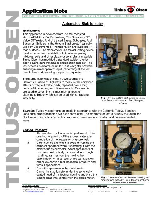
<strong>Automated</strong> <strong>Stabilometer</strong><br />
Background:<br />
This application is developed around the accepted<br />
standard “Method For Determining The Resistance “R”<br />
Value Of Treated And Untreated Bases, Subbases, And<br />
Basement Soils using the Hveem <strong>Stabilometer</strong>” typically<br />
used by Departments of Transportation and suppliers of<br />
road surfaces. The stabilometer is a triaxial testing device<br />
used to determine the stability of bituminous paving<br />
mixtures, soils and other plastic or semi-plastic materials.<br />
<strong>Tinius</strong> <strong>Olsen</strong> has modified a standard stabilometer by<br />
adding a pressure transducer and position encoder. The<br />
test process is automated under Test Navigator software<br />
ensuring minimal operator input, performing all the test<br />
calculations and providing a report as requested.<br />
The stabilometer was originally developed by the<br />
California Division of Highways to measure the combined<br />
effects of frequent traffic loads, repeated over a long<br />
period of time, on a given bituminous mix. Test results<br />
are used to determine the maximum amount of<br />
bituminous binder which can be used without causing<br />
instability.<br />
Samples: Typically specimens are made in accordance with the California Test 301 and are<br />
used once exudation tests have been completed. The stabilometer test is actually the fourth part<br />
of a five part test, after compaction, exudation pressure determination and measurement of R<br />
value.<br />
Testing Procedure<br />
1. The stabilometer test must be performed within<br />
one hour of pouring off the excess water after<br />
completion of the expansion pressure test.<br />
2. Care must be exercised to avoid disrupting the<br />
compact specimen while transferring it from the<br />
mold to the stabilometer. A test specimen that<br />
has been destructively disrupted due to rough<br />
handling, transfer from the mold to the<br />
stabilometer, or as a result of the test itself, will<br />
exhibit excessively high horizontal pressure and<br />
turns displacement.<br />
3. Place the specimen in the stabilometer<br />
4. Center the stabilometer under the spherically<br />
seated head of the testing machine and bring the<br />
loading head into contact with the stabilometer.<br />
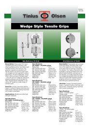
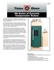
Fig 1. Typical system configuration using a<br />
modified stabilometer and Test Navigator<br />
software<br />
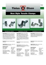
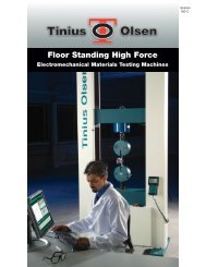
Fig 2. Close up of the stabilometer showing the<br />
modifications made by <strong>Tinius</strong> <strong>Olsen</strong> to make the<br />
system more automated<br />
European Headquarters<br />
Salfords, Surrey, RH1 6TL, England, UK<br />
Telephone: +44 1737 765001 Facsimile: +44 1737 765001
5. Apply a horizontal pressure of 35kPa (5 psi) to the test specimen by turning the pump<br />
handle.<br />
6. Apply a vertical load to the test specimen at a rate of 1.3 mm/min (0.05 in/min). When<br />
the vertical load reaches 8,900 N (2.000 lbf), record the horizontal pressure.<br />
7. Immediately reduce the vertical load to 4,450 N (1,000 lbf)<br />
8. Reduce the horizontal pressure to 35kPa (5 psi) by turning the pump handle counter<br />
clockwise and tare the displacement. Reducing the horizontal pressure will result in a<br />
further reduction of the vertical load – this is normal and should be ignored.<br />
9. Turn the pump handle clockwise at a rate of approx two turns per second until the<br />
stabilometer gage reads 690 kPa (100 psi) and record the displacement.<br />
10. Release the vertical load and the horizontal load, and remove the specimen.<br />
With the modifications that have been implemented by <strong>Tinius</strong> <strong>Olsen</strong>, the above procedure is<br />
automated with the exception of placing the specimen in the stabilometer and applying the<br />
horizontal loading by turning the pump handle.<br />
Calculations<br />
[ 100 ÷ ( ( 2.<br />
5 ÷ d)<br />
( ( Pv ÷ ) −1<br />
) 1)<br />
]<br />
R = 100 −<br />
Ph +<br />
where R = R value by <strong>Stabilometer</strong><br />
Pv = 1.1 MPa vertical pressure<br />
Ph = <strong>Stabilometer</strong> Ph at 8,900 N and<br />
d = displacement<br />
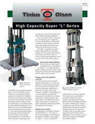
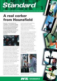
Typical Results<br />
Fig 3. Typical<br />
results as seen on<br />
the software. Note<br />
that these results<br />
come from a<br />
calibration puck<br />
and may not<br />
represent actual<br />
results.
Fig 4. Statistical process control chart that<br />
comes with the Test Navigator software as<br />
standard. Again these were obtained from a<br />
calibration puck so may not be typical .<br />
Relevant test Methods include; ASTM D1560, D2844; AAHTO T-190, T-246; CA-301, CA-366