Controls and Flow Meters - Chemline Plastics Limited
Controls and Flow Meters - Chemline Plastics Limited
Controls and Flow Meters - Chemline Plastics Limited

Create successful ePaper yourself
Turn your PDF publications into a flip-book with our unique Google optimized e-Paper software.
Variable Area <strong>Flow</strong> <strong>Meters</strong><br />
6<br />
5<br />
4<br />
8<br />
1<br />
2<br />
3<br />
7<br />
D<br />
©<strong>Chemline</strong> <strong>Plastics</strong> <strong>Limited</strong> 2008<br />
A<br />
B<br />
L<br />
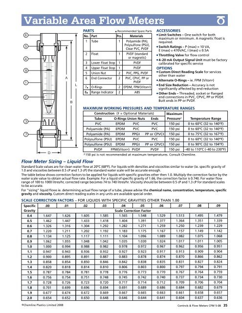
PARTS ▲ Recommended Spare Parts<br />
No. Part Pcs. Materials<br />
1 Tube 1 Polyamide (PA),<br />
Polysulfone (PSU),<br />
Clear PVC, PVDF<br />
2 Float 1 PVDF (st<strong>and</strong>ard<br />
or magnetic)<br />
3 Lower Float Stop 1 PVDF<br />
4 Upper Float Stop 1 PVDF<br />
5 Union Nut 2 PVC, PPG, PVDF<br />
6 End Connector 2 PVC, CPVC, PP or<br />
PVDF<br />
7▲ O-Rings 2 EPDM, FPM(Viton ®)<br />
8▲ Range Indicator 2 ABS<br />
Construction (‡ = Optional Materials)<br />
Tube O-Rings Union Nuts<br />
PVC EPDM PVC<br />
Polyamide (PA) EPDM PVC<br />
Polyamide (PA) EPDM PPG‡<br />
Polysulfone (PSU) EPDM PVC<br />
Polysulfone (PSU) EPDM PPG‡<br />
PVDF FPM(Viton PVDF<br />
®)<br />
MAXIMUM WORKING PRESSURES AND TEMPERATURE RANGES<br />
Maximum<br />
Ends Pressure Temperature Range<br />
PVC<br />
0 to 60ºC (32 to 140ºF)<br />
PVC<br />
0 to 60ºC (32 to 140ºF)<br />
PP or CPVC‡<br />
0 to 75ºC (32 to 167ºF)<br />
PVC<br />
0 to 60ºC (32 to 140ºF)<br />
PP or CPVC‡<br />
0 to 90ºC (32 to 194ºF)<br />
PVDF<br />
–40 to 110ºC (–40 to 230ºF)<br />
2<br />
150 psi<br />
150 psi<br />
150 psi<br />
150 psi<br />
150 psi<br />
150 psi<br />
2 150 psi is not recommended at maximum temperatures. Consult <strong>Chemline</strong>.<br />
SCALE CORRECTION FACTORS – FOR LIQUIDS WITH SPECIFIC GRAVITIES OTHER THAN 1.00<br />
Specific .00 .01 .02 .03 .04 .05 .06 .07<br />
Gravity<br />
Scale Correction Factor<br />
0.4 1.647 1.626 1.605 1.585 1.565 1.548 1.529 1.513<br />
0.5 1.462 1.447 1.433 1.418 1.404 1.391 1.377 1.364<br />
0.6 1.326 1.316 1.304 1.292 1.282 1.271 1.259 1.250<br />
0.7 1.220 1.211 1.202 1.192 1.183 1.175 1.167 1.157<br />
0.8 1.134 1.125 1.117 1.111 1.104 1.096 1.089 1.082<br />
0.9 1.062 1.055 1.048 1.042 1.035 1.030 1.024 1.017<br />
1.0 1.000 0.994 0.988 0.982 0.978 0.972 0.967 0.962<br />
1.1 0.947 0.943 0.936 0.932 0.927 0.923 0.917 0.913<br />
1.2 0.900 0.895 0.891 0.887 0.883 0.878 0.874 0.870<br />
1.3 0.858 0.854 0.850 0.846 0.842 0.838 0.835 0.831<br />
1.4 0.820 0.818 0.814 0.810 0.806 0.803 0.800 0.797<br />
1.5 0.787 0.784 0.781 0.778 0.776 0.773 0.770 0.767<br />
1.6 0.756 0.754 0.751 0.748 0.745 0.742 0.740 0.737<br />
1.7 0.728 0.726 0.723 0.720 0.717 0.714 0.712 0.709<br />
1.8 0.701 0.699 0.696 0.694 0.691 0.689 0.686 0.684<br />
1.9 0.677 0.674 0.672 0.669 0.667 0.665 0.663 0.661<br />
2.0 0.654 0.652 0.650 0.648 0.646 0.644 0.641 0.604<br />
ACCESSORIES<br />
● Limit Switches – One switch for both<br />
maximum or minimum. A magnetic float is<br />
required.<br />
● Switch Ratings – P (max) = 10 VA,<br />
E (max) = 470VAC, I (max) = 0.5A<br />
● Throttling Valve for flow control<br />
● 4–20 mA Output Signal Unit must be factory<br />
calibrated for specific service<br />
OPTIONS<br />
● Custom Direct Reading Scale for services<br />
other than water<br />
● Alternate O-Rings – ie. FPM (Viton ®)<br />
● End Size Reduction – Accuracy is not<br />
significantly affected by end reduction<br />
● Other Ends – Threaded, socket or flanged<br />
end connections in PVC, CPVC, PP or PVDF.<br />
Butt ends in PP or PVDF.<br />
<strong>Flow</strong> Meter Sizing – Liquid <strong>Flow</strong><br />
St<strong>and</strong>ard Scale values are for clean water flow at 20ºC (68ºF). For liquids with densities <strong>and</strong> viscosities similar to water (ie. specific gravity of<br />
1.0 <strong>and</strong> viscosities between 0.5 cP <strong>and</strong> 1.3 cP) the st<strong>and</strong>ard water scale will be accurate enough.<br />
The table below shows correction factors to be applied for liquids with specific gravities other then 1.0. Multiply the correction factor by the<br />
water scale value to obtain actual flow rate. Example: For a liquid of specific gravity of 1.66, the correction factor is 0.740. For water flow<br />
range of 100 to 1000 litres/hr, corrected range becomes 74 to 740 litres/hr. Viscosity should be between 0.5 cP <strong>and</strong> 1.3 cP for st<strong>and</strong>ard scales<br />
to be accurate.<br />
For "sizing" liquid flows ie. determining actual flow range of a tube, please advise the chemical name, concentration, temperature, specific<br />
gravity <strong>and</strong> viscosity. Custom direct reading scales in any units are available special order.<br />
.08<br />
1.495<br />
1.351<br />
1.239<br />
1.149<br />
1.075<br />
1.011<br />
0.956<br />
0.909<br />
0.866<br />
0.827<br />
0.794<br />
0.764<br />
0.734<br />
0.706<br />
0.682<br />
0.658<br />
0.637<br />
.09<br />
1.479<br />
1.339<br />
1.229<br />
1.142<br />
1.068<br />
1.005<br />
0.951<br />
0.904<br />
0.862<br />
0.824<br />
0.791<br />
0.759<br />
0.730<br />
0.704<br />
0.679<br />
0.657<br />
0.636<br />
<strong>Controls</strong> & <strong>Flow</strong> <strong>Meters</strong> CFM 5-08 35