Installation Manual - MK Electric
Installation Manual - MK Electric
Installation Manual - MK Electric

You also want an ePaper? Increase the reach of your titles
YUMPU automatically turns print PDFs into web optimized ePapers that Google loves.
CONTENTS Page<br />
A Introduction 2<br />
B Product Range 3<br />
C Safety Instructions 5<br />
D <strong>Installation</strong> 6<br />
E Operating Instructions 18<br />
Masterseal<br />
Switch Modules, Enclosures,<br />
Neon Indicator Modules<br />
56420 GRY, 56421 GRY, 56422 GRY, 56836, 56881, 56882,<br />
56883, 56889, 56891, 56892, 56893, 56896, 56910, 56915.<br />
Page<br />
F Testing 19<br />
G Fault Diagnosis 20<br />
H Service and Maintenance 22<br />
I Disposal Instructions 23<br />
J Guarantee 23<br />
Please leave this leaflet with the 1 consumer for future reference<br />
C. SAFETY INSTRUCTIONS<br />
1. It is essential that, prior to installation or maintenance, the<br />
user/installer disconnects the electrical supply before<br />
commencing work.<br />
2. This product should be installed by a competent person<br />
(e.g. a qualified electrician) in accordance with the instructions<br />
supplied with the product and in accordance with the<br />
appropriate clauses of the current edition of the IEE wiring<br />
regulations (BS 7671).<br />
3. It is essential that all connections are made as instructed, that<br />
cables are not stressed and that terminals are fully tightened .<br />
4. All switches, except push switches, do not have to be derated<br />
when used with fluorescent or inductive loads. All switches<br />
conform to BS3676 Pt. 1 1989<br />
5. If metal conduit enters the back box in more than one position,<br />
earth continuity must be maintained.<br />
6. These products conform to their relevant British Standards,<br />
Switches BS 3676 Pt.1 and Neons BS 5733, are manufactured in<br />
accordance with BS EN ISO 9002 and comply with the LV<br />
(72/23/EEC) Directive.<br />
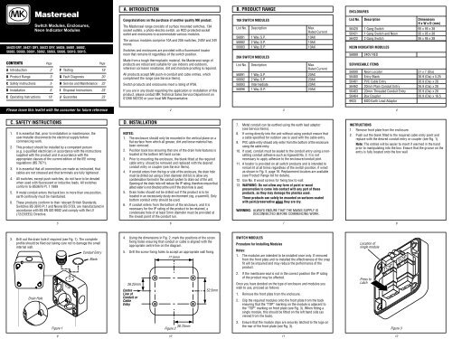
3. Drill out the drain hole if required (see Fig. 1). The complete<br />
profile should be filed out taking care not to damage the small<br />
internal wall.<br />
Drain Hole<br />
5<br />
Figure 1<br />
9<br />
TOP<br />
Conduit Entry<br />
Blank<br />
A. INTRODUCTION<br />
Congratulations on the purchase of another quality <strong>MK</strong> product.<br />
The Masterseal range consists of surface mounted switches, 13A<br />
socket outlets, a photo-electric switch, an RCD protected socket<br />
outlet and enclosures to accommodate various modules.<br />
The various modules comprise 10A and 20A switches, 240V and 24V<br />
neons.<br />
Switches and enclosures are provided with a fluorescent locator<br />
neon that remains lit regardless of the switch position.<br />
Made from a tough thermoplastic material, the Masterseal range of<br />
products are robust and suitable for use indoors and outdoors,<br />
wherever corrosion resistance, dirt and moisture proofing is required.<br />
All products accept <strong>MK</strong> push-in conduit and cable entries, which<br />
compliment the range (see Service Items).<br />
Switch products and enclosures meet a rating of IP56.<br />
If you are in any doubt regarding the application or installation of this<br />
product, please contact <strong>MK</strong> Technical Sales Service Department on<br />
01268 563720 or your local <strong>MK</strong> Representative.<br />
D. INSTALLATION<br />
2<br />
NOTES:<br />
1. The enclosure should only be mounted in the vertical plane on a<br />
flat surface from which all grease, dirt and loose material has<br />
been removed.<br />
2. Position back box ensuring that one of the drain hole features is<br />
located at the bottom left hand corner.<br />
3. Prior to mounting the enclosure, the blank fitted at the required<br />
cable entry, should be removed and replaced with the desired<br />
conduit entry or coupler (see Service Items).<br />
4. If conduit enters from the top or side of the enclosure, the drain hole<br />
must be drilled out using a 5mm diameter drill bit, to allow any<br />
condensation formed in the conduit system to drain out of the unit.<br />
Opening of the drain hole will reduce the IP rating, therefore ensure that<br />
jetted water is not directed at the unit if the drain hole is used.<br />
5. Drain holes should not be drilled out if the product is to be<br />
located in an excessively dusty environment (eg. a sawmill). Only<br />
bottom conduit entry should be used.<br />
6. If conduit enters from the bottom of the enclosure, and it is<br />
necessary for the IP rating of the product to be retained, a<br />
condensate hole of at least 5mm diameter must be provided at<br />
the lowest point of the conduit run.<br />
4. Using the dimensions in Fig. 2, mark the positions of the screw<br />
fixing holes ensuring that conduit or cable is aligned with the<br />
appropriate centre line on the diagram.<br />
5. Drill the screw fixing holes to accept an appropriate wall fixing.<br />
26.25mm<br />
Centre<br />
Line of<br />
Conduit or<br />
Cable<br />
Entry<br />
6<br />
77.5mm<br />
38.75mm<br />
Figure 2<br />
10<br />
52.5mm<br />
B. PRODUCT RANGE<br />
10A SWITCH MODULES<br />
List No. Description Max.<br />
Rated Current<br />
56881 1 Way S.P. 10AX<br />
56882 2 Way S.P. 10AX<br />
56883 1 Way D.P. 10AX<br />
20A SWITCH MODULES<br />
List No. Description Max.<br />
Rated Current<br />
56891 1 Way S.P. 20AX<br />
56892 2 Way S.P. 20AX<br />
56893 Intermediate 20AX<br />
56896 1 Way D.P. 20AX<br />
3<br />
7. Metal conduit can be earthed using the earth lead adaptor<br />
(see Service Items).<br />
8. If wiring directly into the unit without using conduit ensure that<br />
a cable specified for outdoor use is used with the cable entry.<br />
9. PVC cable entry should only enter from the bottom of the enclosure<br />
using the cable entry.<br />
10. If used, conduit must be sealed to the conduit entry using a nonsetting<br />
conduit adhesive such as Egaweld No. 2. It is not<br />
necessary to apply adhesive to the enclosure/conduit joint.<br />
11. A locator is provided on all switch products and is intended to<br />
remain lit at all times regardless of the switch position, if wired<br />
as shown in Fig. 5, page 16. Replacement locators are available<br />
(see Product Range list for details).<br />
12. Use No. 8 wood screws for fixing box to wall.<br />
13. WARNING: Do not allow any form of paint or wood<br />
preservative to come into contact with any part of these<br />
products, as they may damage the plastics used.<br />
These products can safely be mounted on surfaces coated<br />
with paint/preservative when they are dry.<br />
WARNING: ALWAYS ENSURE THAT THE MAINS SUPPLY IS<br />
DISCONNECTED BEFORE COMMENCING WORK.<br />
7<br />
SWITCH MODULES<br />
Procedure for Installing Modules<br />
Notes:<br />
1. The modules are intended to be installed once only. If removed<br />
from the front plate and re-installed the effectiveness of the snap<br />
fit will be impaired and may reduce the performance of the<br />
product.<br />
2. If the membrane seal is not in the correct position the IP rating<br />
of the product may be affected.<br />
Once you have decided on the type of enclosure and modules you<br />
wish to use, proceed as follows:<br />
1. Remove the front plate from the enclosure.<br />
2. Clip the required modules onto the front plate from the back<br />
ensuring that the “TOP” marking on the module is adjacent to<br />
the “TOP” marking on front plate (see Fig. 3). When fitting a<br />
single module, this should be fitted on the left hand side (as<br />
viewed from the back).<br />
3. Ensure that the module clips are securely latched to the lugs on<br />
the rear of the front plate (see Fig. 3).<br />
11<br />
ENCLOSURES<br />
List No. Description Dimensions<br />
H x W x D (mm)<br />
56420 1 Gang Switch 95 x 95 x 38<br />
56421 1 Gang Switch and Neon 95 x 95 x 38<br />
56422 2 Gang Switch 95 x 95 x 38<br />
NEON INDICATOR MODULES<br />
56889 240V RED<br />
SERVICEABLE ITEMS<br />
56890 Neon Locator 31 x 7 (Dia)<br />
56460 Entry Blank 26.9 (Dia) x 5.25<br />
56461 PVC Cable Entry 26.9 (Dia) x 28<br />
56462 20mm Plain Conduit Entry 26.9 (Dia) x 28<br />
56463 20mm Threaded Conduit Entry 26.9 (Dia) x 28<br />
56464 Box Coupler 26.9 (Dia) x 16.5<br />
9933 M20 Earth Lead Adaptor<br />
4<br />
INSTRUCTIONS<br />
1. Remove front plate from the enclosure.<br />
2. Push out the blank fitted to the required cable entry point and<br />
replace with the desired conduit entry or coupler (see Fig. 1).<br />
Note: The entries will be easier to insert if warmed in the hand<br />
prior to manipulating into the box. Ensure that the groove on the<br />
entry is fully located onto the box wall.<br />
Location of<br />
single module<br />
Press to<br />
Latch<br />
TOP<br />
8<br />
Figure 3<br />
12<br />
TOP
4. If a neon indicator module is being used, ensure that the neon is<br />
located on the correct side of the front plate (see Fig. 4) as<br />
indicated by the membrane seal. Neon modules are installed as<br />
described on pages 12 and 13.<br />
TOP<br />
NEON<br />
Figure 4<br />
13<br />
SWITCH<br />
PROCEDURE FOR REMOVING THE MODULES<br />
If a module is found to be faulty or unserviceable and requires<br />
replacement, proceed as follows:<br />
1. Using a flat bladed screwdriver carefully lever the uppermost<br />
module clips upwards over the front plate lugs and remove<br />
module (see Fig. 7).<br />
2. If the module clips break during this procedure ensure that all<br />
loose parts are removed from the product.<br />
Figure 7<br />
17<br />
TOP<br />
TOP<br />
REPLACEMENT OF NEON LOCATOR<br />
Note:<br />
The neon locator should be replaced whenever it is found to be<br />
unserviceable.<br />
Replacement locators are available (refer to Product Range<br />
List/Serviceable Items).<br />
To replace a neon locator proceed as follows:<br />
(a) Switch off and disconnect the mains supply to the product.<br />
(b) Remove the front plate and disconnect the locator wires.<br />
(c) Using a flat bladed screwdriver remove and discard the<br />
faulty locator referring to Fig. 9.<br />
(d) Fit new locator, pushing into place, and, referring to Fig. 5,<br />
wire in position.<br />
(e) Refit front plate and reconnect and switch on the mains<br />
supply to the product.<br />
21<br />
5. Locate the conduit or cable in the required entry and screw the<br />
back box to the wall.<br />
6. Fit the required modules to the front plate (see page 12).<br />
7. Before fitting front plate ensure that the holes in the box seal are<br />
aligned with the fixing screw holes and the slot around the seal<br />
is aligned with the ribs in the enclosure.<br />
8. Refer to the wiring diagram (Fig. 5) and wire in position. Ensure<br />
that wires are of sufficient length to allow easy access to rear of<br />
front plate, but short enough to fit comfortably inside enclosure<br />
when front plate is secured.<br />
Note: If the enclosure seal is not correctly positioned the IP rating of<br />
the product may be affected.<br />
14<br />
E. OPERATING INSTRUCTIONS<br />
1. Press lower edge of rocker until engaged in ON position<br />
(see Fig. 8).<br />
2. On those products fitted with a neon indicator ensure that the<br />
indicator lights when the switch is ON.<br />
3. On units fitted with Press Switches ensure that the rocker<br />
returns to the OFF position when released.<br />
Press<br />
Figure 8<br />
18<br />
Figure 9<br />
H. SERVICE AND MAINTENANCE<br />
CLEANING<br />
1. The exterior of the products should only be cleaned using a<br />
solution of mild detergent (eg. washing-up liquid) and warm water.<br />
2. Polycarbonate is a highly durable material which is ideal for use<br />
in most environments. However you should seek advice from<br />
<strong>MK</strong> Technical Sales Service Department before installing in<br />
environments where chemicals, synthetic oils or harsh cleaners<br />
are likely to be used.<br />
22<br />
LOAD LOAD<br />
L1 L2<br />
Locator<br />
Neutral<br />
L NBlock<br />
SUPPLY<br />
1 GANG<br />
S.P. 1 WAY<br />
56881 / 56891<br />
LOAD<br />
L<br />
F. TESTING<br />
LOAD<br />
L<br />
Locator<br />
Neutral<br />
L NBlock<br />
SUPPLY<br />
1 GANG<br />
S.P. 2 WAY<br />
56882 / 56892<br />
L L<br />
Locator<br />
Neutral<br />
NBlock<br />
SUPPLY<br />
INTERMEDIATE<br />
56893<br />
Figure 5<br />
15<br />
LOAD<br />
L<br />
LOAD<br />
L N<br />
Locator<br />
L N<br />
SUPPLY<br />
1 GANG<br />
D.P. 1 WAY<br />
56883 / 56896<br />
Indicator<br />
Neutral<br />
L NBlock<br />
SUPPLY<br />
1 GANG AND<br />
NEON INDICATOR<br />
56421<br />
Neutral<br />
Block<br />
Note: Completed installation should be tested in accordance with<br />
the latest edition of the IEE wiring regulations (BS 7671).<br />
J. GUARANTEE<br />
19<br />
I. DISPOSAL INSTRUCTIONS<br />
Product and packaging should be disposed of via civic amenity<br />
facilities at the end of its useful life.<br />
The company undertakes to replace or repair at its discretion<br />
products should they become defective within 20 years in the case of<br />
electromechanical Wiring Device products and 10 years in the case<br />
of mains related electronic Wiring Device products and all Circuit<br />
Protection and Cable Management products solely as a result of<br />
faulty materials and or workmanship. Understandably if the product<br />
has not been installed or maintained in accordance with the<br />
company’s instructions, has not been used appropriately or if any<br />
attempt has been made to rectify, dismantle or alter the product in<br />
any way the guarantee will be invalidated.<br />
This Guarantee states the company’s entire liability. It does not<br />
extend to cover consequential loss or damage or installation costs<br />
arising from the defective product. This Guarantee does not restrict<br />
or infringe the normal statutory or other rights of the consumer.<br />
23<br />
9. Fit the front plate to the enclosure. Do not overtighten the front<br />
plate fixing screws (see Fig. 6).<br />
Front Plate Fixing Screws<br />
G. FAULT DIAGNOSIS<br />
Figure 6<br />
16<br />
SWITCH PRODUCTS<br />
1. If the service (e.g. lights) connected to the product fails to<br />
operate, check the service is functioning, the wiring is correct<br />
and the main fuse is intact. Then either contact your local<br />
electrician or proceed as follows:<br />
(a) Switch off and disconnect the mains supply to the switch.<br />
(b) Remove front plate and check that wiring is correct in<br />
accordance with the relevant wiring diagram and all<br />
terminals are sufficiently tightened.<br />
(c) Replace front plate, reconnect and switch on mains and<br />
check operation of service (e.g. lights).<br />
(d) If service (e.g. lights) still fails to operate, switch off and<br />
disconnect mains supply and contact <strong>MK</strong> <strong>Electric</strong> Technical<br />
Sales Service Department or your local <strong>MK</strong> Representative.<br />
2. If, on those products fitted with neon indicators, the indicator<br />
fails to light, the complete neon module should be replaced.<br />
Contact <strong>MK</strong> <strong>Electric</strong> Technical Sales Service Department or your<br />
local <strong>MK</strong> Representative.<br />
20<br />
<strong>MK</strong> <strong>Electric</strong> wishes to make it clear that it owns all the original<br />
designs of the products which it manufactures (whether or not listed<br />
in this leaflet) and that it will take all necessary legal action in any<br />
part of the world against any party found to be manufacturing,<br />
distributing, selling or otherwise dealing with any article which<br />
infringes the company’s copyrights or patents in its products, or any<br />
other right of the company therein.<br />
Registered Design No. Patent Pending<br />
2025117 9300338<br />
Design Right M.K. <strong>Electric</strong> Ltd.<br />
It’s simply safer to say <strong>MK</strong> <br />
<strong>MK</strong> <strong>Electric</strong> Limited<br />
The Arnold Centre, Paycocke Road, Basildon, Essex SS14 3EA<br />
Telephone 01268 563000 Facsimile 01268 563563 (UK Sales)<br />
Facsimile 01268 563360 (International)<br />
email: more@mkelectric.co.uk<br />
Web site: www.mkelectric.co.uk<br />
All marks in this document identified with a ® or symbol<br />
adjacent to the mark are Trade Marks of <strong>MK</strong> <strong>Electric</strong> Limited 40433PL Ed.6<br />
24<br />
®