Installation Manual - MK Electric
Installation Manual - MK Electric
Installation Manual - MK Electric

Create successful ePaper yourself
Turn your PDF publications into a flip-book with our unique Google optimized e-Paper software.
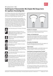
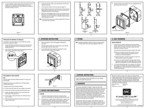
4. If a neon indicator module is being used, ensure that the neon is<br />
located on the correct side of the front plate (see Fig. 4) as<br />
indicated by the membrane seal. Neon modules are installed as<br />
described on pages 12 and 13.<br />
TOP<br />
NEON<br />
Figure 4<br />
13<br />
SWITCH<br />
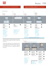
PROCEDURE FOR REMOVING THE MODULES<br />
If a module is found to be faulty or unserviceable and requires<br />
replacement, proceed as follows:<br />
1. Using a flat bladed screwdriver carefully lever the uppermost<br />
module clips upwards over the front plate lugs and remove<br />
module (see Fig. 7).<br />
2. If the module clips break during this procedure ensure that all<br />
loose parts are removed from the product.<br />
Figure 7<br />
17<br />
TOP<br />
TOP<br />
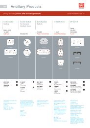
REPLACEMENT OF NEON LOCATOR<br />
Note:<br />
The neon locator should be replaced whenever it is found to be<br />
unserviceable.<br />
Replacement locators are available (refer to Product Range<br />
List/Serviceable Items).<br />
To replace a neon locator proceed as follows:<br />
(a) Switch off and disconnect the mains supply to the product.<br />
(b) Remove the front plate and disconnect the locator wires.<br />
(c) Using a flat bladed screwdriver remove and discard the<br />
faulty locator referring to Fig. 9.<br />
(d) Fit new locator, pushing into place, and, referring to Fig. 5,<br />
wire in position.<br />
(e) Refit front plate and reconnect and switch on the mains<br />
supply to the product.<br />
21<br />
5. Locate the conduit or cable in the required entry and screw the<br />
back box to the wall.<br />
6. Fit the required modules to the front plate (see page 12).<br />
7. Before fitting front plate ensure that the holes in the box seal are<br />
aligned with the fixing screw holes and the slot around the seal<br />
is aligned with the ribs in the enclosure.<br />
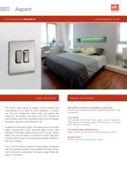
8. Refer to the wiring diagram (Fig. 5) and wire in position. Ensure<br />
that wires are of sufficient length to allow easy access to rear of<br />
front plate, but short enough to fit comfortably inside enclosure<br />
when front plate is secured.<br />
Note: If the enclosure seal is not correctly positioned the IP rating of<br />
the product may be affected.<br />
14<br />
E. OPERATING INSTRUCTIONS<br />
1. Press lower edge of rocker until engaged in ON position<br />
(see Fig. 8).<br />
2. On those products fitted with a neon indicator ensure that the<br />
indicator lights when the switch is ON.<br />
3. On units fitted with Press Switches ensure that the rocker<br />
returns to the OFF position when released.<br />
Press<br />
Figure 8<br />
18<br />
Figure 9<br />
H. SERVICE AND MAINTENANCE<br />
CLEANING<br />
1. The exterior of the products should only be cleaned using a<br />
solution of mild detergent (eg. washing-up liquid) and warm water.<br />
2. Polycarbonate is a highly durable material which is ideal for use<br />
in most environments. However you should seek advice from<br />
<strong>MK</strong> Technical Sales Service Department before installing in<br />
environments where chemicals, synthetic oils or harsh cleaners<br />
are likely to be used.<br />
22<br />
LOAD LOAD<br />
L1 L2<br />
Locator<br />
Neutral<br />
L NBlock<br />
SUPPLY<br />
1 GANG<br />
S.P. 1 WAY<br />
56881 / 56891<br />
LOAD<br />
L<br />
F. TESTING<br />
LOAD<br />
L<br />
Locator<br />
Neutral<br />
L NBlock<br />
SUPPLY<br />
1 GANG<br />
S.P. 2 WAY<br />
56882 / 56892<br />
L L<br />
Locator<br />
Neutral<br />
NBlock<br />
SUPPLY<br />
INTERMEDIATE<br />
56893<br />
Figure 5<br />
15<br />
LOAD<br />
L<br />
LOAD<br />
L N<br />
Locator<br />
L N<br />
SUPPLY<br />
1 GANG<br />
D.P. 1 WAY<br />
56883 / 56896<br />
Indicator<br />
Neutral<br />
L NBlock<br />
SUPPLY<br />
1 GANG AND<br />
NEON INDICATOR<br />
56421<br />
Neutral<br />
Block<br />
Note: Completed installation should be tested in accordance with<br />
the latest edition of the IEE wiring regulations (BS 7671).<br />
J. GUARANTEE<br />
19<br />
I. DISPOSAL INSTRUCTIONS<br />
Product and packaging should be disposed of via civic amenity<br />
facilities at the end of its useful life.<br />
The company undertakes to replace or repair at its discretion<br />
products should they become defective within 20 years in the case of<br />
electromechanical Wiring Device products and 10 years in the case<br />
of mains related electronic Wiring Device products and all Circuit<br />
Protection and Cable Management products solely as a result of<br />
faulty materials and or workmanship. Understandably if the product<br />
has not been installed or maintained in accordance with the<br />
company’s instructions, has not been used appropriately or if any<br />
attempt has been made to rectify, dismantle or alter the product in<br />
any way the guarantee will be invalidated.<br />
This Guarantee states the company’s entire liability. It does not<br />
extend to cover consequential loss or damage or installation costs<br />
arising from the defective product. This Guarantee does not restrict<br />
or infringe the normal statutory or other rights of the consumer.<br />
23<br />
9. Fit the front plate to the enclosure. Do not overtighten the front<br />
plate fixing screws (see Fig. 6).<br />
Front Plate Fixing Screws<br />
G. FAULT DIAGNOSIS<br />
Figure 6<br />
16<br />
SWITCH PRODUCTS<br />
1. If the service (e.g. lights) connected to the product fails to<br />
operate, check the service is functioning, the wiring is correct<br />
and the main fuse is intact. Then either contact your local<br />
electrician or proceed as follows:<br />
(a) Switch off and disconnect the mains supply to the switch.<br />
(b) Remove front plate and check that wiring is correct in<br />
accordance with the relevant wiring diagram and all<br />
terminals are sufficiently tightened.<br />
(c) Replace front plate, reconnect and switch on mains and<br />
check operation of service (e.g. lights).<br />
(d) If service (e.g. lights) still fails to operate, switch off and<br />
disconnect mains supply and contact <strong>MK</strong> <strong>Electric</strong> Technical<br />
Sales Service Department or your local <strong>MK</strong> Representative.<br />
2. If, on those products fitted with neon indicators, the indicator<br />
fails to light, the complete neon module should be replaced.<br />
Contact <strong>MK</strong> <strong>Electric</strong> Technical Sales Service Department or your<br />
local <strong>MK</strong> Representative.<br />
20<br />
<strong>MK</strong> <strong>Electric</strong> wishes to make it clear that it owns all the original<br />
designs of the products which it manufactures (whether or not listed<br />
in this leaflet) and that it will take all necessary legal action in any<br />
part of the world against any party found to be manufacturing,<br />
distributing, selling or otherwise dealing with any article which<br />
infringes the company’s copyrights or patents in its products, or any<br />
other right of the company therein.<br />
Registered Design No. Patent Pending<br />
2025117 9300338<br />
Design Right M.K. <strong>Electric</strong> Ltd.<br />
It’s simply safer to say <strong>MK</strong> <br />
<strong>MK</strong> <strong>Electric</strong> Limited<br />
The Arnold Centre, Paycocke Road, Basildon, Essex SS14 3EA<br />
Telephone 01268 563000 Facsimile 01268 563563 (UK Sales)<br />
Facsimile 01268 563360 (International)<br />
email: more@mkelectric.co.uk<br />
Web site: www.mkelectric.co.uk<br />
All marks in this document identified with a ® or symbol<br />
adjacent to the mark are Trade Marks of <strong>MK</strong> <strong>Electric</strong> Limited 40433PL Ed.6<br />
24<br />
®