

Product Overview Ignition Systems - Smitsvonk Holland BV
Product Overview Ignition Systems - Smitsvonk Holland BV
Product Overview Ignition Systems - Smitsvonk Holland BV

Create successful ePaper yourself
Turn your PDF publications into a flip-book with our unique Google optimized e-Paper software.
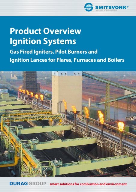
<strong>Product</strong> <strong>Overview</strong><br />
<strong>Ignition</strong> <strong>Systems</strong><br />
Gas Fired Igniters, Pilot Burners and<br />
<strong>Ignition</strong> Lances for Flares, Furnaces and Boilers<br />
smart solutions for combustion and environment
2<br />
Introduction<br />
For more than half a century <strong>Smitsvonk</strong> has<br />
been making low-tension high-energy ignition<br />
and control systems for industrial combustion<br />
processes. These electrical and electronic ignition<br />
systems are applied world-wide. They are<br />
characterized by a high degree of reliability<br />
under demanding conditions. <strong>Ignition</strong> is not effected<br />
by dirt, humidity, extreme temperatures<br />
or aggressive gases.<br />
The <strong>Smitsvonk</strong> ignition principle<br />
<strong>Smitsvonk</strong>’s low tension high energy ignition<br />
system is designed to meet the requirements of<br />
reliable ignition for many industrial applications.<br />
The system is based upon the principle of a<br />
capacitor discharge over a special discharge<br />
surface. This surface consists of an isolator with<br />
semiconductor properties. The isolator and positive<br />
and negative electrodes are integrated into<br />
a high temperature resistant spark plug. When<br />
a charged capacitor is connected, it will be discharged<br />
via the spark plug producing sparks,<br />
even under wet or soiled conditions.<br />
Process step by step<br />
1 Charge capacitor<br />
2 Capacitor connected to spark plug through<br />
high voltage thyristor<br />
3 As capacitor discharges a current forms across<br />
the semi conductor surface of the spark plug<br />
4 The area above the insulator becomes ionised<br />
5 Resulting flame shaped spark forms a plasma.<br />
Current from 300–1000 A in 5 to 15 µs<br />
Applications<br />
● Ground and elevated flares<br />
● Industrial furnaces and boilers<br />
● Pulverized coal fired power plants<br />
● Portable igniters<br />
● Waste incinerators<br />
● Gas engines/turbines<br />
This system has the following<br />
advantages<br />
● Moisture, dirt, oil and grease will not effect<br />
the ignition<br />
● Not limitation for cable length<br />
● Low power consumption<br />
● Insensitive to process pressure<br />
● Self cleaning spark plug surface, due to flame<br />
shaped spark<br />
● Tension is low in comparison to traditional<br />
ignition sources<br />
● Easy construction for explosion proof execution.<br />
The system comprises:<br />
● A power supply with varying capacities<br />
● Control electronics with variable pulse frequencies<br />
● A thyristor<br />
● A connection cable<br />
● <strong>Smitsvonk</strong> low tension spark tip.<br />
power<br />
supply<br />
transformer rectifier<br />
impulse<br />
generator<br />
control<br />
capacitor thyristor<br />
spark tip<br />
high<br />
energy<br />
pulse
Flare <strong>Ignition</strong> <strong>Systems</strong><br />
Flaring systems in a refinery, petrochemical<br />
plant or steel plant ensure the safe and efficient<br />
disposal of relieved gases. A flare is expected to<br />
operate twenty-four hours a day. The flare system<br />
must be in service for several years without<br />
a need for maintenance. Therefore proper design<br />
and operation are extremely important.<br />
<strong>Ignition</strong> of the waste gases can be done by pilot<br />
burners (flame) or for some applications by ignition<br />
lances (spark).<br />
The ignition system must reliably ignite the<br />
waste gas of the flare. If the ignition system fails,<br />
unburned hydrocarbons and/or toxic gases<br />
could be released into the atmosphere.<br />
SMITSVONK Flame Front Generator Panel with Extra High<br />
Energy <strong>Ignition</strong><br />
<strong>Smitsvonk</strong> flare ignition systems<br />
A: Classic flare ignition,<br />
flame front ignition<br />
A flame front generator<br />
is a system in which<br />
a gas/air mixture is<br />
introduced at ground<br />
level and flows up a<br />
one-inch line to the<br />
pilot burner.<br />
After filling this<br />
line with the<br />
mixture it is<br />
ignited by a<br />
spark. The<br />
resulting flame<br />
travels to the<br />
top of the flare<br />
where the<br />
pilot burner is<br />
ignited.<br />
flame front ignition<br />
(gas/air mixture)<br />
pilot gas consumption:<br />
3–5 Nm 3 /hr,<br />
26,000–43,800 Nm 3 /year<br />
C: Combination of A and B<br />
flame front connection<br />
B: Gas-electric flare<br />
ignition<br />
A premixed, self-aspirating<br />
pilot burner<br />
with 3 integrated<br />
spark plugs.<br />
Electrical<br />
ignition<br />
with<br />
three integrated<br />
spark plugs<br />
located away<br />
from the high<br />
heat radiation<br />
zone<br />
pilot gas consumption:<br />
1.5–3 Nm 3 /hr,<br />
13,000–26,000 Nm 3 /year<br />
3
4<br />
Pilot Burner<br />
<strong>Ignition</strong> of waste gas from pipe<br />
flares, air and steam assisted flares<br />
and ground flares<br />
For most flare systems the pilot burner can<br />
not be accessed for service. Maintenance or<br />
replacement is not possible while the flare is in<br />
operation. To safeguard operation, <strong>Smitsvonk</strong>’s<br />
pilots provide reliable ignition and stable burning<br />
even under the most difficult climate conditions.<br />
Features<br />
● High energy ignition<br />
● <strong>Ignition</strong> by three integrated spark plugs<br />
● Long lifetime, longer maintenance intervals<br />
● Insensitive to moisture and dirt<br />
● Complete delivery; cables, junction boxes and<br />
ignition unit<br />
● Easy fit cable connectors<br />
● Self-aspirating or forced air supply<br />
● Integrated and protected thermocouple<br />
● Functionally tested to client specifications<br />
● Construction completely out of high temperature-resistant<br />
stainless steel<br />
Applications<br />
● <strong>Ignition</strong> of all kind of flares in the (petro)<br />
chemical, oil and gas, steel and biogas industry<br />
common data<br />
pipe diameter 2“ (60 mm) materials mainly 310 SST<br />
length 1200, 2326 or 2500 mm windcap diameter 4“<br />
Heavy duty pilot burner with radiation shield to protect the<br />
electrical connections<br />
Pilot burners in different lengths and shapes<br />
design angled or straight mounting hooks included<br />
air requirement self-aspirating flame detection by thermocouple type K<br />
gas connection 1/2“ BSPM option double thermocouple<br />
supply gas natural gas or propane/<br />
butane<br />
refinery gas<br />
(max. 40 vol% H2 )<br />
2 separate thermocouples<br />
options<br />
refinery gas, up to 100% H2 ,<br />
coke gas,<br />
biogas
Pilot Burner Selection Table for Small and Medium Size Flares<br />
model<br />
number<br />
ST57(60)AF13/2326/360/25/TW<br />
length: 2326 mm<br />
option for thermocouple<br />
ST57(60)AF13/2326/360/25/DTW<br />
option for extra flame front ignition:<br />
ST57(60)AF13/2326/360/25/TW-FFG<br />
ST57(60)AF13/1200/TW<br />
length: 1200 mm<br />
option for thermocouple<br />
ST57(60)AF13/1200/DTW<br />
ST57(60)AF13/2500/360/25/TW<br />
length: 2500 mm<br />
option for thermocouple<br />
ST57(60)AF13/2500/360/25/DTW<br />
option for extra flame front ignition:<br />
ST57(60)AF13/2500/360/25/TW-FFG<br />
ST57(60)AF19/2326/360/25/TW<br />
length: 2326 mm<br />
option for thermocouple:<br />
ST57(60)AF19/2326/360/25/DTW<br />
option for extra flame front ignition:<br />
ST57(60)AF19/2326/360/25/TW-FFG<br />
ST57(60)AF19/2500/360/25/TW<br />
length: 2500 mm<br />
option for thermocouple<br />
ST57(60)AF19/2500/360/25/DTW<br />
option for extra flame front ignition:<br />
ST57(60)AF19/2500/360/25/TW–FFG<br />
for biogas<br />
ST57(60)BF19/1200/T3<br />
length: 1200 mm<br />
for coke gas<br />
ST57(60)WF13/2326/360/25/TW<br />
length: 2326 mm<br />
for low pressure<br />
ST76(60)AF23/2326/360/25/T6<br />
length: 2326 mm<br />
Straight construction<br />
Angled construction<br />
design heat<br />
release<br />
based on<br />
natural<br />
gas in kW<br />
gas flow in<br />
nm 3 /hr<br />
required<br />
pressure<br />
angled 10–17 1–1.7 0.5–1.5 natural gas or propane/<br />
butane or refinery gas<br />
(max. 40% H 2 )<br />
angled 10–17 1–1.7 0.5–1.5 natural gas or propane/<br />
butane or refinery gas<br />
(max. 40% H 2)<br />
straight 10–17 1–1.7 0.5–1.5 natural gas or propane/<br />
butane or refinery gas<br />
(max. 40% H 2 )<br />
angled 15–29 1.5–2.9 0.2–0.8 natural gas or propane/<br />
butane or refinery gas<br />
(max. 40% H 2 )<br />
straight 15–29 1.5–2.9 0.2–0.8 natural gas or propane/<br />
butane or refinery gas<br />
(max. 40% H 2 )<br />
straight 4–6<br />
biogas<br />
angled 15–25<br />
coke gas<br />
angled 6–17 1.5–2.3 40–100<br />
mBarg<br />
gas ignition thermocouple<br />
3 integrated spark plugs<br />
at flame side<br />
3 spark plugs and extra<br />
flame front tube<br />
3 integrated spark plugs<br />
at flame side<br />
tube<br />
3 integrated spark plugs<br />
at flame side<br />
3 spark plugs and extra<br />
flame front tube<br />
3 integrated spark plugs<br />
at flame side<br />
3 spark plugs and extra<br />
flame front tube<br />
3 integrated spark plugs<br />
at flame side<br />
3 spark plugs and extra<br />
flame front tube<br />
0.7–0.9 0.07–0.1 bio gas 3 integrated spark plugs<br />
at flame side<br />
3–5 0.1–0.3 coke gas 40–60% H 2<br />
rest CO<br />
3 integrated spark plugs<br />
at flame side<br />
natural gas 3 integrated spark plugs<br />
at flame side<br />
single<br />
double<br />
single<br />
double<br />
single<br />
double<br />
single<br />
double<br />
single<br />
double<br />
single<br />
single<br />
single<br />
5
6<br />
Pilot Burner Selection Table for Large Flares (Heavy Duty Applications)<br />
model<br />
number<br />
HDEP60AF19/2326/360/25/TW<br />
length: 2326 mm<br />
option for thermocouple<br />
HDEPST60AF19/2326/360/25/DTW<br />
HDEPST60AF19/2326/360/25/2TW<br />
option for extra flame front ignition:<br />
ST60AF13/2326/360/25/TW-FFG<br />
HDEPST60AF19/2500/360/TW<br />
length: 2500 mm<br />
option for thermocouple:<br />
HDEPST60AF19/2500/360/DTW<br />
HDEPST60AF19/2500/360/2TW<br />
option for extra flame front ignition:<br />
ST60AF13/2500/360/TW-FFG<br />
Heavy duty pilot burner with a hybrid ignition system:<br />
Integrated spark plugs and flame front ignition<br />
design heat<br />
release<br />
based on<br />
natural<br />
gas in kW<br />
gas flow<br />
in nm 3 /hr<br />
required<br />
pressure<br />
angled 16–30 1.6–3.0 0.2–0.8 natural gas or<br />
propane/butane or<br />
refinery gas<br />
(max. 40% H2)<br />
angled 16–30 1.6–3.0 0.2–0.8 natural gas or<br />
propane/butane or<br />
refinery gas<br />
(max. 40% H 2)<br />
gas ignition thermocouple<br />
3 integrated spark<br />
plugs at 1.8 m from<br />
the top<br />
3 spark plugs and extra<br />
flame front tube<br />
3 integrated spark<br />
plugs at 1.9 m from<br />
the top<br />
3 spark plugs and extra<br />
flame front tube<br />
single<br />
double<br />
2 pieces<br />
single<br />
double<br />
2 pieces
Pilot Burner Inquiry Check List<br />
Location<br />
Type Plant type<br />
Flare tip type<br />
Flare tip manufacturer<br />
Diameter of flare tip<br />
Total height<br />
Drawing of the flare tip available<br />
Min./max. flow of the waste gas<br />
Composition of the waste gas<br />
Number of pilot burners required<br />
Pilot gas pressure available min.: max.: Barg<br />
Pilot gas composition<br />
Location of the ignition/control unit<br />
Explosion proof required<br />
ATEX or other<br />
For gas group IIB or IIC, zone 1 or 2<br />
Power supply available:<br />
Other requirements:<br />
Accessories<br />
High temperature (775°C) ignition cable with<br />
connector and SST protection hose<br />
High temperature (775°C) thermocouple cable<br />
with connector and SST protection hose<br />
SST junction box for ignition or thermocouple<br />
signal<br />
Low temperature ignition cable<br />
Low temperature thermocouple cable<br />
<strong>Ignition</strong> and control unit (see pages 15 and 16)<br />
yes no<br />
yes no<br />
7
8<br />
Continuous Electronic<br />
Spark Flare <strong>Ignition</strong><br />
Features<br />
● No gas consumption; offering considerable<br />
savings<br />
● Substantial reduction of investment costs<br />
since no gas lines, valves, instrumentation or<br />
electrical control system for the pilot burner<br />
are needed<br />
Applications<br />
● Coke oven flares<br />
● Pipe flares with hydrogen in the waste gas<br />
● Temporary flares from tank farms<br />
Direct spark ignition of a coke oven flare<br />
Description<br />
<strong>Smitsvonk</strong> has decades of experience with<br />
direct electric ignition of flare units. A reproducible,<br />
high energy, highly reliable spark<br />
(described in the literature as “plasma ignition”)<br />
that is not susceptible to external influences<br />
such as moisture and dirt, guarantees the safe<br />
ignition and combustion of the residual gas in<br />
the flare.<br />
Such direct electric spark ignition may, for<br />
example, be used in flares firing coke oven gas<br />
and flares where fuel gas containing a minimum<br />
of 6% hydrogen is burnt at relatively low flame<br />
velocities in the flare head.<br />
In addition, the spark ignition module employed<br />
by <strong>Smitsvonk</strong> offers the decisive advantage<br />
of thyristor-controlled circuitry that is not<br />
subjected to wear and tear. The ignition system<br />
is designed to withstand the long operation and<br />
maintenance cycles typical for these types of<br />
industries.<br />
The construction of the ignition lance depends<br />
on exit velocity, gas composition and the<br />
number of operation hours. The number of<br />
lances depends on the flare diameter.<br />
<strong>Ignition</strong> and control<br />
unit, see pages 15<br />
and 16
<strong>Ignition</strong> Lances<br />
Direct ignition of (pilot) burners,<br />
flares and other processes<br />
Features<br />
● Built to client specifications<br />
● High temperature resistance<br />
● Long life time<br />
● Easy fit cable connectors<br />
● Insensitive to moisture<br />
● Exchangeable spark plug<br />
Applications<br />
● Burners and flares<br />
Options<br />
● explosion proof versions<br />
● for thermocouple<br />
● for flexible lances<br />
● for special bent lances<br />
● for angled spark plug.<br />
<strong>Ignition</strong> Lances for Flares<br />
diameter 26.7 mm 26.7 mm 26.7 mm 26.7 mm<br />
type<br />
26.7T/L/<br />
TK18/18<br />
Angled (45°) ignition lance Angled (180°)<br />
ignition lance<br />
26.7T/L/<br />
TK18/18-35<br />
26.7T/L/90/<br />
TK18/18<br />
26.7T/L/120/<br />
90AH/TK18/18-CF<br />
construction straight angled spark plug angled lance 45° angled lance 180°<br />
length L 300–1000 mm: 300–1000 mm: 1500, 2000 or 2300 or 3000 mm<br />
multiple of 100 mm, multiple of 100 mm, 2300 mm<br />
1000–2000 mm: 1000–2000 mm:<br />
multiple of 100 mm, multiple of 100 mm,<br />
2000–3000 mm: 2000–3000 mm:<br />
200 mm intervals 200 mm intervals<br />
tube material 310 SST 310 SST 310 SST 310 SST<br />
electrical M30 easy fit M30 easy fit M30 easy fit M30 easy fit<br />
connection connector<br />
connector<br />
connector<br />
connector<br />
mounting hooks option option fixed or adjustable fixed or adjustable<br />
options - thermocouple - thermocouple - thermocouple - thermocouple<br />
- explosion proof - explosion proof - explosion proof - explosion proof<br />
- ATEX<br />
- ATEX<br />
- ATEX<br />
- ATEX<br />
II 2G EEx d IIC T6 II 2G EEx d IIC T6 II 2G EEx d IIC T6 II 2G EEx d IIC T6<br />
9
10<br />
<strong>Ignition</strong> Lances<br />
For burners and processes<br />
Accessories<br />
● High temperature (775 °C) ignition cable with<br />
connector and SST protection hose<br />
● High temperature (775 °C) thermocouple cable<br />
with connector and SST protection hose<br />
● SST junction box for ignition or thermocouple<br />
signal<br />
● Low temperature ignition cable<br />
● Low temperature thermocouple cable<br />
● <strong>Ignition</strong> and control unit (see pages 15 and<br />
16).<br />
Spark Plugs<br />
● All types of low tension high energy spark<br />
plugs to replace existing high tension systems<br />
● Standard mechanical connection: M10, M14<br />
and M18<br />
<strong>Ignition</strong> Lances for Burners and Processes<br />
diameter 17.2 mm 17.2 mm 15 mm<br />
type 17.2/L/TP14/12 17.2/L/TP14/12-JB 15.7/L/TP12/JB<br />
design straight straight straight<br />
length L<br />
200–1000 mm:<br />
200–1000 mm:<br />
200–1000 mm:<br />
multiple of 100 mm, multiple of 100 mm, multiple of 100 mm,<br />
1000–2000 mm:<br />
1000–2000 mm:<br />
1000–2000 mm:<br />
multiple of 100 mm, multiple of 100 mm, multiple of 100 mm,<br />
2000–3000 mm:<br />
2000–3000 mm:<br />
2000–3000 mm:<br />
200 mm intervals<br />
200 mm intervals<br />
200 mm intervals<br />
tube material 310 SST 310 SST 316 SST<br />
electrical connection M25 easy fit connector<br />
material: 316 SST<br />
junction box<br />
material: aluminium<br />
junction box<br />
material: aluminium<br />
mounting hooks option fixed or adjustable option<br />
option<br />
- flexible lance<br />
- flexible lance<br />
- flexible lance<br />
- special bent shape - special bent shape - special bent shape<br />
- mounting adapter - mounting adapter - mounting adapter<br />
- ATEX II2G EEx dIIC T6 - ATEX II2G EEx dIIC T6 - ATEX II2G EEx dIIC T6
Gas Fired Igniters<br />
Tube Ø54 mm<br />
<strong>Ignition</strong> of main burners in furnaces,<br />
boilers, power plants and incinerators<br />
Features and Benefits<br />
● High energy ignition<br />
● Insensitive to moisture<br />
● Sstainless steel construction<br />
● Self-aspirating, forced air supply or combination<br />
● For self-aspirating version no air supply line<br />
required<br />
● Insensitive to pressure fluctuations<br />
● Robust design<br />
● For all kind of gases and pressures<br />
● Integrated spark plug(s) and ionisation electrode<br />
● Explosion proof version (ATEX) available<br />
Applications<br />
● Main burners of furnaces, boilers, incinerators<br />
and power plants.<br />
Self-aspirating <strong>Ignition</strong> Burner<br />
type N54APV13/L/A/V2E N54APV13/L/A/V3E N54APV13/L/A/V5E<br />
heat release with natural gas 80–132 kW 115–192 kW 185–305 kW<br />
heat release with propane 120–195 kW 170–285 kW 280–458 kW<br />
min. max pressure 0.5–1.5 Barg<br />
length L<br />
400, 500, 600: multiple of 100 mm,<br />
from 1000 to 2000 mm: 200 mm intervals,<br />
2000, 2500, 3000 mm<br />
air inlet A 165, 230 or 400 mm in steps of 10 mm<br />
connection to main burner Flange 2½“ ANSI 150 LBS RF<br />
gas connection 1/2“ BSPF 3/4“ BSPF 3/4“ BSPF<br />
air conn. for forced draft 1/2“ BSPF 1/2“ BSPF 1/2“ BSPF<br />
ignition by 3 integrated spark plugs<br />
flame detection ionisation<br />
tube material 310 SST<br />
connection material 316 SST<br />
electrical connection M25 connector for ignitition, M25 connector for ionisation<br />
protection IP65<br />
Explosion Proof Self-aspirating <strong>Ignition</strong> Burner<br />
type 54APVD13/L/A/VE 54APVD13/L/A/V2E 54APVD13/L/A/V5E<br />
heat release with natural gas 46–75 kW 80–132 kW 185–305 kW<br />
heat release with propane 67–109 kW 120–195 kW 280–458 kW<br />
min. max. pressure 0.5–1.5 Barg<br />
length L<br />
400, 500, 600: multiple of 100 mm,<br />
from 1000 to 2000 mm: 200 mm intervals<br />
2000, 2500, 3000 mm<br />
air inlet A 165, 230 or 400 mm in steps of 10 mm<br />
connection to main burner flange 2½“ ANSI 150 LBS RF<br />
gas connection ½“ NPTF ½“ NPTF ½“ NPTF<br />
air conn. for forced draft ½“ BSPF ½“ BSPF ½“ BSPF<br />
ignition 3 integrated spark plugs<br />
flame detection ionisation<br />
tube material 310 SST<br />
connection material 316 SST<br />
electrical connection explosion proof connection housing<br />
protection IP65<br />
explosion proof ATEX II G EEx D IIC T6<br />
11
12<br />
Gas Fired Igniters<br />
Tube Ø48.3 mm<br />
<strong>Ignition</strong> of main burners in furnaces,<br />
boilers, power plants and incinerators<br />
Features and Benefits<br />
● High energy ignition<br />
● Insensitive to moisture<br />
● Stainless steel construction<br />
● Self-aspirating, forced air supply or combination<br />
● For self-aspirating version no air supply line<br />
required<br />
● Insensitive to pressure fluctuations<br />
● Rugged design<br />
● For all kind of gases and pressures<br />
● Integrated spark plugs(s) and ionisation electrode<br />
● Explosion proof version (ATEX) available<br />
Applications<br />
● Main burners of furnaces, boilers, incinerators<br />
and power plants<br />
Igniter connection<br />
Self-aspirating <strong>Ignition</strong> Burner<br />
type JB48APV13/L/A/VE JB48APV13/L/A/V2E JB48APV13/L/A/V4E<br />
heat release with natural gas 46–75 kW 80–132 kW 150–250 kW<br />
heat release with propane 67–109 kW 120–195 kW 226–370 kW<br />
min. max. pressure 0.5–1.5 Barg<br />
length L<br />
400, 500, 600: multiple of 100 mm,<br />
from 1000 to 2000 mm: 200 mm intervals,<br />
2000, 2500, 3000 mm<br />
air inlet A ≥300 mm in steps of 10 mm<br />
connection to main burner flange 2“ ANSI 150 LBS RF<br />
gas connection 3/8“ NPTF 3/8“ NPTF 3/8“ NPTF<br />
air conn. for forced draft option option option<br />
ignition integrated spark plug<br />
flame detection ionisation<br />
tube material 310 SST<br />
connection material 316 SST<br />
electrical connection connection housing<br />
protection IP65<br />
Explosion Proof Self-aspirating <strong>Ignition</strong> Burner<br />
type 48APVD13/L/A/VE 48APVD13/L/A/V2E 48APVD13/L/A/V4E<br />
heat release with natural gas 46–75 kW 80–132 kW 150–250 kW<br />
heat release with propane 67–109 kW 120–195 kW 226–370 kW<br />
min. max. pressure 0.5–1.5 Barg<br />
length L<br />
400, 500, 600: multiple of 100 mm,<br />
from 1000 to 2000 mm: 200 mm intervals,<br />
2000, 2500, 3000 mm<br />
air inlet A ≥300 mm in steps of 10 mm<br />
connection to main burner flange 2“ ANSI 150 LBS RF<br />
gas connection ½“ NPTF ½“ NPTF ½“ NPTF<br />
air conn. for forced draft ½“ BSPF ½“ BSPF ½“ BSPF<br />
ignition integrated spark plug<br />
flame detection ionisation<br />
tube material 310 SST<br />
connection material 316 SST<br />
electrical connection explosion proof connection housing<br />
protection IP65<br />
explosion proof ATEX II 2G EEx d IIC T6
Gas Fired Igniters<br />
Tube Ø38 mm<br />
<strong>Ignition</strong> of main burners in furnaces,<br />
boilers, power plants and incinerators<br />
Features and Benefits<br />
● High energy ignition<br />
● Insensitive to moisture<br />
● Stainless steel construction<br />
● Self-aspirating, forced air supply or combination<br />
● No air supply line required for self-aspirating<br />
version<br />
● Insensitive to pressure fluctuations<br />
● Rugged design<br />
● For all kind of gases and pressures<br />
● Integrated spark plugs(s) and ionisation electrode<br />
● Explosion proof version (ATEX) available<br />
Applications<br />
● Main burners of furnaces, boilers, incinerators<br />
and power plants<br />
Self-aspirating <strong>Ignition</strong> Burner<br />
type 38ALV/L/A/VE<br />
heat release with natural gas 17–29 kW<br />
heat release with propane 24–39 kW<br />
min. max pressure 0.5–1.5 Barg<br />
length L<br />
400, 500 600: multiple of 100 mm<br />
from 1000 to 2000: 200 mm intervals<br />
2000, 2500, 3000 mm<br />
air inlet A ≥300 mm in steps of 10 mm<br />
connection to main burner flange 1½“ ANSI 150 LBS RF<br />
gas connection 3/8“ NPTF<br />
air conn, for forced draft option<br />
ignition by 1 integrated spark plug<br />
flame detection ionisation<br />
tube material 310 and 321 SST<br />
connection material 316 SST<br />
electrical connection M25 connector for ignition, M25 connector for ionisation<br />
protection IP65<br />
Explosion Proof Self-aspirating <strong>Ignition</strong> Burner<br />
type 38APVD/L/A/VE<br />
heat release with natural gas 17–29 kW<br />
heat release with propane 24–39 kW<br />
min. max pressure 1.5 Barg<br />
length L<br />
400, 500 600: multiple of 100 mm<br />
from 1000 to 2000: 200 mm intervals<br />
2000, 2500, 3000 mm<br />
air inlet A ≥ 300 mm in steps of 10 mm<br />
connection to main burner flange 1½“ ANSI 150 LBS RF<br />
gas connection ½“ NPTF<br />
air conn, for forced draft ½“ BSPF<br />
ignition integrated spark plug<br />
flame detection ionisation<br />
tube material 310 and 321 SST<br />
connection material 316 SST<br />
electrical connection explosion proof connection housing<br />
protection IP65<br />
explosion proof ATEX II 2G EEx d IIC T6<br />
13
14<br />
Igniter (<strong>Ignition</strong> Burner) Inquiry Check List<br />
Location<br />
Type plant type<br />
Location<br />
Application<br />
Furnace draft/pressure<br />
Igniter mounting position<br />
Igniter outer tube diameter<br />
Gas specification<br />
Gas pressure<br />
Area classification<br />
Total length (L)<br />
Air sleeves position (A)<br />
Insert length (X)<br />
Flame control<br />
Required heat release<br />
Required flame length<br />
Mounting flange<br />
Frequency of use<br />
Air connection<br />
Air temperature<br />
Air pressure or wind box pressure<br />
furnace<br />
ionisation<br />
boiler<br />
self-aspirating version<br />
Ambient air temperature min.: max.:<br />
Distance to ignition/control unit<br />
For ignition units see pages 15 and 16<br />
incinerator<br />
forced air supply (option)
<strong>Ignition</strong> Units<br />
<strong>Ignition</strong> and burner control for ignition<br />
burner, pilots burners, lances<br />
and spark plugs<br />
Features and Benefits<br />
● High energy ignition<br />
● Capacitor discharge with thyristor/diode<br />
● 100% Electronic, no wear<br />
● Wide range of power supply voltages.<br />
● Low power consumption<br />
● No limitation for cable length for flare ignition<br />
units<br />
Applications<br />
● Furnaces<br />
● Boilers<br />
● Incinerators<br />
<strong>Ignition</strong> units for igniters of furnaces, boilers and incinerators<br />
type E-LIGHT 2000V 162609 E-LIGHT 2000V-233311-SV98H-CR<br />
function ignition ignition, flame detection and remote start<br />
spark energy 2 J 2 Je<br />
spark tension 2000 V 2000 V<br />
spark frequency 2 Hz 2 Hz<br />
power supply 230, 115 or 24 VAC 50–60 Hz 230, 115 or 24 VAC 50–60 Hz<br />
power consumption 15 VA 22 VA<br />
housing aluminum aluminum<br />
dimensions LxWxH 260 x 160 x 90 mm 230 x 230 x 110 mm<br />
protection IP65 IP65<br />
remote start relay: n/a 24, 48 VDC, 110 or 230 VAC<br />
flame relay n/a ionisation SV98H<br />
Explosion proof, same specification only different dimensions<br />
type E-LIGHT 2000V CCA/GUB03 E-LIGHT 2000V-CCA/GUB04-SV98H-CR<br />
explosion proof ATEX II 2G EEx d IIC T6 ATEX II 2G EEx d IIC T6<br />
dimensions LxWxH 276 x 276 x 217 mm 430 x 430 x 290 mm<br />
15
16<br />
<strong>Ignition</strong> Units<br />
<strong>Ignition</strong> and burner control for<br />
ignition burners, pilots burners,<br />
lances and spark plugs<br />
<strong>Ignition</strong> Units for Igniters of Furnaces, Boilers and Incinerators<br />
type BWO(EE) 2/2 SV98H-CR<br />
function ignition, flame detection and remote start<br />
design EEx d housing for ignition unit and relays<br />
EEx e housing for terminals<br />
spark energy appr. 8 J<br />
spark tension 2000 Volt<br />
spark frequency 2 Hz<br />
power supply 230, 115 or 24 VAC 50–60 Hz<br />
power consumption 25 VA<br />
housing painted steel<br />
dimensions 605 x 235 x 268 mm<br />
protection IP 65<br />
remote start relay 24 VDC<br />
flame relay ionisation SV98H<br />
explosion proof ATEX II 2G EEx de IIC T6<br />
<strong>Ignition</strong> Units for Pilot Burners of Flares (longer distance) Common Data<br />
function ignition and flame detection for pilot burner(s) or ignition lance(s)<br />
power supply 230, 115 or 24 VAC 50–60 Hz,<br />
option: for DC or battery back-up<br />
ignition 100% electronic, type SVECU<br />
spark energy 9 or 18 J<br />
spark tension 3000 Volt<br />
spark frequency 0,5 or 2 Hz depends on type pilot burner or lance.<br />
flame detection thermocouple relay type K<br />
control by small PLC<br />
enclosure IP66 general purpose or explosion proof (ATEX),<br />
option: explosion proof for IIC<br />
material painted steel for IP66 enclosure, cast aluminium for ex-proof enclosure,<br />
option: SST enclosure<br />
LED signal lamps yellow power on, green for pilot on, red for pilot off, red for ignition failure<br />
switches main power isolator, start, stop, reset and lamp test<br />
contacts pilot on/off, ignition failure,<br />
option for 4–20 mA<br />
type SVECU X/2-EJB5-<br />
H4D4ST-L-CR<br />
for one pilot burner for two pilot burners for three pilot burners<br />
2 SVECU X/2-EJB4/5-<br />
H4D6S2T-L-CR<br />
3 SVECU X/2-2EJB5-<br />
H4D8S3T-L-CR<br />
construction 1 EEx d housing 2 EEx d housing 2 EEx d housings<br />
number of ignition units 1 2 3<br />
max. distance 250 m 250 m 250 m<br />
option for 500 m 500 m<br />
500 m<br />
option: for more pilot<br />
burners
Portable <strong>Ignition</strong> Units<br />
Lightweight, battery operated<br />
ignition unit<br />
Features<br />
● Compact and lightweight unit weighs only<br />
6 kg<br />
● High energy ignition<br />
● Easy to replace rechargeable battery pack<br />
● Ergonomically designed, easy to handle.<br />
● Battery status indicator<br />
Application<br />
● Direct spark ignition of industrial burners in<br />
absence of fixed igniters<br />
Schematic<br />
Ø15<br />
breathing gland<br />
M25<br />
connector for<br />
battery charger<br />
battery<br />
monitor<br />
260<br />
main<br />
switch<br />
L =<br />
hexagon socket<br />
head screw M6<br />
115<br />
shoulder belt<br />
adjustable stopring<br />
Ø40 x Ø15 x Ø15 mm<br />
4-core cable<br />
with armor<br />
L=2.5 m<br />
type SPI<br />
ignition type high energy<br />
spark frequency 3 Hz<br />
battery type reloadable 12 V<br />
battery capacity<br />
3.2 AH (suitable for 3 hours of continuous<br />
operation)<br />
protection class IP65<br />
housing material aluminum<br />
total weight (L=1000 mm) 6 kg<br />
battery charger power supply 220–240 VAC<br />
power consumption 17 W<br />
100<br />
loading time 300 min<br />
push button<br />
17
18<br />
Semi Portable <strong>Ignition</strong><br />
Unit<br />
Explosion proof ignition unit with<br />
ignition lance to ignite main burner<br />
in furnaces or boilers. <strong>Ignition</strong> can be<br />
controlled by a remote switch.<br />
Features<br />
● Explosion proof ignition unit<br />
● High energy ignition<br />
● Operation controlled by remote switch<br />
● Easy to handle.<br />
Application<br />
● Direct spark ignition for industrial burners in<br />
absence of fixed igniters.<br />
15<br />
356<br />
316<br />
276<br />
power supply cable<br />
Ø14<br />
L 115<br />
adjustable stopping<br />
Ø40 X 15<br />
276<br />
236<br />
ignition high Energy<br />
spark energy 2 J<br />
spark tension 2 kV<br />
spark frequency 2 Hz<br />
protection hose 20 m<br />
max. temperature 120°C<br />
4-core cable<br />
power supply 220–240 VAC 50–60 Hz, option 24 VAC or 115 VAC<br />
power consumption 20 VA<br />
protection class IP65<br />
explosion proof ATEX II 2G EEx d IIC T6<br />
housing material aluminum<br />
lance material 316 SST<br />
handgrip material aluminum<br />
lance diameter 15 mm<br />
lance length L 500–2000 mm, in steps of 100 mm<br />
option bent lance<br />
100<br />
push button
Mobile <strong>Ignition</strong> Units<br />
<strong>Ignition</strong> of main burners at places<br />
where a fixed pilot burner or igniter<br />
is not available and a spark is insufficient<br />
to ignite the main burner.<br />
Features<br />
● High energy ignition unit<br />
● Insensitive to moisture and dirt<br />
● Self-aspirating SST igniter<br />
● Available for different gases and pressures.<br />
Application<br />
● Furnaces<br />
● Boilers<br />
● Ground flares.<br />
4-wheeled trolly<br />
2-wheeled trolly 4-wheeled trolly<br />
consisting of: consisting of:<br />
self-aspirating igniter type 7<br />
diameter: 38 mm<br />
length: 1000 mm (other lengths possible)<br />
capacity: 20 kW<br />
gas: propane<br />
igniter materials: 316 and 321 SST<br />
self-aspirating igniter type 51<br />
diameter: 48 and 51 mm<br />
length: 1000 mm (other lengths possible)<br />
capacity: 180–350 kW<br />
gas: propane<br />
igniter materials: 310 and 316 SST<br />
explosion proof (ATEX 2G IIB) high energy ignition unit explosion proof (ATEX 2G IIC) high energy ignition unit<br />
explosion proof switch explosion proof switch<br />
explosion proof solenoid valve explosion proof solenoid valve<br />
pressure reducer with downstream pressure gauge pressure reducer with downstream pressure gauge<br />
2 reels, including all cabling and gas hose 2 reels, including all cabling and gas hose<br />
11 m gas hose and ignition cable 11 m gas hose and ignition cable<br />
25 m power supply cable 25 m for power supply cable<br />
suitable for 24, 120 or 230 VAC suitable for 24, 120 or 230 VAC<br />
IP 65 enclosure for instruments IP 65 enclosure for instruments<br />
not included: gas bottles not included: gas bottles<br />
options:<br />
- igniter diameter 25 mm (not for natural gas)<br />
- ionisation flame detection<br />
- LPG, butane, natural gas or refinery gas<br />
2-wheeled trolly<br />
options:<br />
- wall mounted version with longer cable lengths<br />
- ionisation flame detection<br />
- LPG, butane, natural gas or refinery gas<br />
19
DURAG GmbH<br />
Kollaustraße 105<br />
22453 Hamburg, Germany<br />
Tel. +49 (0)40 55 42 18-0<br />
Fax +49 (0)40 58 41 54<br />
E-Mail: info@durag.de<br />
DVN – DURAG Vertrieb/Service Nord<br />
Kollaustraße 105<br />
22453 Hamburg, Germany<br />
Tel. +49 (0)40 55 42 18-0<br />
Fax +49 (0)40 58 41 54<br />
E-Mail: dvn@durag.de<br />
DVO – DURAG Vertrieb/Service Ost<br />
Meißner Ring 4<br />
09599 Freiberg, Germany<br />
Tel. +49 (0)3731 30 04-0<br />
Fax +49 (0)3731 30 04-22<br />
E-Mail: durag.freiberg@durag.de<br />
DVS – DURAG Vertrieb/Service Süd<br />
Weidenweg 16<br />
73087 Bad Boll, Germany<br />
Tel. +49 (0)7164 912 25-0<br />
Fax +49 (0)7164 912 25-50<br />
E-Mail: info@dvs-badboll.de<br />
DVW – DURAG Vertrieb/Service West<br />
An der Pönt 53a<br />
40885 Ratingen, Germany<br />
Tel. +49 (0)2102 74 00-0<br />
Fax +49 (0)2102 74 00 28<br />
E-Mail: dvw@durag.de<br />
©DURAG GROUP 09/2009· All specifications subject to change without notice<br />
DURAG France S.a.r.l.<br />
Parc GIP Charles de Gaulle<br />
49, rue Léonard de Vinci, BP 70166<br />
95691 Goussainville CEDEX, France<br />
Tel. +33 (0)1 301 811 80<br />
Fax +33 (0)1 393 383 60<br />
E-Mail: info@durag-france.fr<br />
DURAG UK Offi ce<br />
Suite 17, Brookside Business Park<br />
Cold Meece, Stone, Staff ordshire<br />
ST15 0RZ, United Kingdom<br />
Tel. +44 (0)1785 760 007<br />
Fax +44 (0)1785 760 014<br />
E-Mail: durag.uk@durag.de<br />
DURAG, Inc., USA<br />
1355 Mendota Heights Road · Suite 200,<br />
Mendota Heights ·<br />
MN 55120, USA<br />
Tel. +1 651 451-1710<br />
Fax +1 651 457-7684<br />
E-Mail: durag@durag.com<br />
DURAG India Instrumentation Ltd<br />
#143/16, Ground Floor, 4th Main Road<br />
Industrial Town, Rajajinagar<br />
Bengalooru 560 044, India<br />
Tel. +91 (0)80 23 14 56 26<br />
Fax +91 (0)80 23 14 56 26 Ext. 30<br />
E-Mail: info@duragindia.com<br />
www.durag.de<br />
<strong>Smitsvonk</strong> <strong>Holland</strong> B.V.<br />
P.O. Box 180 · 2700 AD Zoetermeer<br />
Loodstraat 57 · 2718 RV Zoetermeer<br />
The Netherlands<br />
Tel. +31 (0)79 361 35 33<br />
Fax +31 (0)79 361 13 78<br />
Email: sales@smitsvonk.nl<br />
DURAG data systems GmbH<br />
Kollaustraße 105,<br />
22453 Hamburg, Germany<br />
Tel. +49 (0)40 55 42 18-3000<br />
Fax +49 (0)40 55 42 18-3099<br />
E-Mail: info@durag-data.de<br />
DURAG process & systems technology gmbh<br />
Kollaustraße 105<br />
22453 Hamburg, Germany<br />
Tel. +49 (0)40 55 42 18-0<br />
Fax +49 (0)40 58 41 54<br />
E-Mail: info@durag-process.de<br />
Hegwein GmbH<br />
Am Boschwerk 7<br />
70469 Stuttgart, Germany<br />
Tel. +49 (0)711 135 788-0<br />
Fax +49 (0)711 135 788-5<br />
E-Mail: info@hegwein.de<br />
VEREWA Umwelt- und Prozessmesstechnik<br />
GmbH<br />
Kollaustraße 105<br />
22453 Hamburg, Germany<br />
Tel. +49 (0)40 55 42 18-0<br />
Fax +49 (0)40 58 41 54<br />
E-Mail: verewa@durag.de<br />
smart solutions for combustion and environment