Y-IM-Single Package AC and Single Package Gas/Electric Units ...
Y-IM-Single Package AC and Single Package Gas/Electric Units ...
Y-IM-Single Package AC and Single Package Gas/Electric Units ...

Create successful ePaper yourself
Turn your PDF publications into a flip-book with our unique Google optimized e-Paper software.
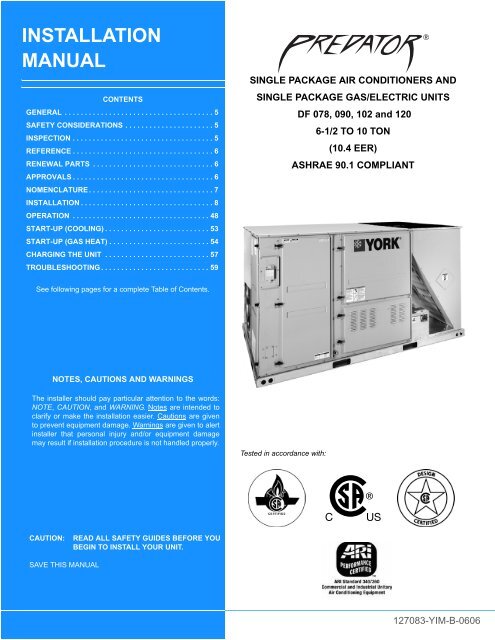
INSTALLATION<br />
MANUAL<br />
CONTENTS<br />
GENERAL . . . . . . . . . . . . . . . . . . . . . . . . . . . . . . . . . . . . . 5<br />
SAFETY CONSIDERATIONS . . . . . . . . . . . . . . . . . . . . . . 5<br />
INSPECTION . . . . . . . . . . . . . . . . . . . . . . . . . . . . . . . . . . . 5<br />
REFERENCE . . . . . . . . . . . . . . . . . . . . . . . . . . . . . . . . . . . 6<br />
RENEWAL PARTS . . . . . . . . . . . . . . . . . . . . . . . . . . . . . . 6<br />
APPROVALS . . . . . . . . . . . . . . . . . . . . . . . . . . . . . . . . . . . 6<br />
NOMENCLATURE . . . . . . . . . . . . . . . . . . . . . . . . . . . . . . . 7<br />
INSTALLATION . . . . . . . . . . . . . . . . . . . . . . . . . . . . . . . . . 8<br />
OPERATION . . . . . . . . . . . . . . . . . . . . . . . . . . . . . . . . . . 48<br />
START-UP (COOLING) . . . . . . . . . . . . . . . . . . . . . . . . . . 53<br />
START-UP (GAS HEAT) . . . . . . . . . . . . . . . . . . . . . . . . . 54<br />
CHARGING THE UNIT . . . . . . . . . . . . . . . . . . . . . . . . . . 57<br />
TROUBLESHOOTING . . . . . . . . . . . . . . . . . . . . . . . . . . . 59<br />
See following pages for a complete Table of Contents.<br />
NOTES, CAUTIONS AND WARNINGS<br />
The installer should pay particular attention to the words:<br />
NOTE, CAUTION, <strong>and</strong> WARNING. Notes are intended to<br />
clarify or make the installation easier. Cautions are given<br />
to prevent equipment damage. Warnings are given to alert<br />
installer that personal injury <strong>and</strong>/or equipment damage<br />
may result if installation procedure is not h<strong>and</strong>led properly.<br />
CAUTION: READ ALL SAFETY GUIDES BEFORE YOU<br />
BEGIN TO INSTALL YOUR UNIT.<br />
SAVE THIS MANUAL<br />
SINGLE P<strong>AC</strong>KAGE AIR CONDITIONERS AND<br />
SINGLE P<strong>AC</strong>KAGE GAS/ELECTRIC UNITS<br />
Tested in accordance with:<br />
DF 078, 090, 102 <strong>and</strong> 120<br />
6-1/2 TO 10 TON<br />
(10.4 EER)<br />
ASHRAE 90.1 COMPLIANT<br />
<br />
127083-Y<strong>IM</strong>-B-0606
GENERAL . . . . . . . . . . . . . . . . . . . . . . . . . . . . . . . . . . . . . . 5<br />
SAFETY CONSIDERATIONS . . . . . . . . . . . . . . . . . . . . . . . 5<br />
INSPECTION . . . . . . . . . . . . . . . . . . . . . . . . . . . . . . . . . . . . 5<br />
REFERENCE . . . . . . . . . . . . . . . . . . . . . . . . . . . . . . . . . . . . 6<br />
RENEWAL PARTS. . . . . . . . . . . . . . . . . . . . . . . . . . . . . . . . 6<br />
APPROVALS . . . . . . . . . . . . . . . . . . . . . . . . . . . . . . . . . . . . 6<br />
NOMENCLATURE . . . . . . . . . . . . . . . . . . . . . . . . . . . . . . . . 7<br />
INSTALLATION . . . . . . . . . . . . . . . . . . . . . . . . . . . . . . . . . . 8<br />
INSTALLATION SAFETY INFORMATION . . . . . . . . . . . . 8<br />
PRECEDING INSTALLATION . . . . . . . . . . . . . . . . . . . . . . 8<br />
L<strong>IM</strong>ITATIONS. . . . . . . . . . . . . . . . . . . . . . . . . . . . . . . . . . . 9<br />
LOCATION. . . . . . . . . . . . . . . . . . . . . . . . . . . . . . . . . . . . 10<br />
RIGGING AND HANDLING . . . . . . . . . . . . . . . . . . . . . . . 11<br />
CLEARANCES. . . . . . . . . . . . . . . . . . . . . . . . . . . . . . . . . 12<br />
DUCTWORK . . . . . . . . . . . . . . . . . . . . . . . . . . . . . . . . . . 15<br />
DUCT COVERS . . . . . . . . . . . . . . . . . . . . . . . . . . . . . . . . 15<br />
CONDENSATE DRAIN . . . . . . . . . . . . . . . . . . . . . . . . . . 16<br />
COMPRESSORS. . . . . . . . . . . . . . . . . . . . . . . . . . . . . . . 16<br />
FILTERS . . . . . . . . . . . . . . . . . . . . . . . . . . . . . . . . . . . . . 16<br />
THERMOSTAT WIRING . . . . . . . . . . . . . . . . . . . . . . . . . 17<br />
POWER AND CONTROL WIRING . . . . . . . . . . . . . . . . . 17<br />
POWER WIRING DETAIL . . . . . . . . . . . . . . . . . . . . . . . . 17<br />
OPTIONAL ELECTRIC HEAT . . . . . . . . . . . . . . . . . . . . . 24<br />
OPTIONAL GAS HEAT . . . . . . . . . . . . . . . . . . . . . . . . . . 25<br />
GAS PIPING . . . . . . . . . . . . . . . . . . . . . . . . . . . . . . . . . . . . . . . 25<br />
GAS CONNECTION . . . . . . . . . . . . . . . . . . . . . . . . . . . . . . . . . 25<br />
LP UNITS, TANKS AND PIPING . . . . . . . . . . . . . . . . . . . . . . . 26<br />
VENT AND COMBUSTION AIR . . . . . . . . . . . . . . . . . . . . . . . . 27<br />
OPTIONS/<strong>AC</strong>CESSORIES . . . . . . . . . . . . . . . . . . . . . . . 27<br />
ELECTRIC HEAT . . . . . . . . . . . . . . . . . . . . . . . . . . . . . . . . . . . 27<br />
MOTORIZED OUTDOOR DAMPER . . . . . . . . . . . . . . . . . . . . 27<br />
ECONOMIZER . . . . . . . . . . . . . . . . . . . . . . . . . . . . . . . . . . . . . 27<br />
POWER EXHAUST . . . . . . . . . . . . . . . . . . . . . . . . . . . . . . . . . 27<br />
RAIN HOOD . . . . . . . . . . . . . . . . . . . . . . . . . . . . . . . . . . . . . . . 27<br />
ECONOMIZER AND POWER EXHAUST SET<br />
POINT ADJUSTMENTS AND INFORMATION . . . . . . . . 27<br />
MIN<strong>IM</strong>UM POSITION ADJUSTMENT . . . . . . . . . . . . . . . . . . . 27<br />
ENTHALPY SET POINT ADJUSTMENT . . . . . . . . . . . . . . . . . 28<br />
POWER EXHAUST DAMPER SET POINT (WITH OR<br />
WITHOUT POWER EXHAUST) . . . . . . . . . . . . . . . . . . . . . . . . 28<br />
INDOOR AIR QUALITY AQ . . . . . . . . . . . . . . . . . . . . . . . . . . . 28<br />
PHASING . . . . . . . . . . . . . . . . . . . . . . . . . . . . . . . . . . . . . 30<br />
BELT TENSION . . . . . . . . . . . . . . . . . . . . . . . . . . . . . . . . 30<br />
AIR BALANCE . . . . . . . . . . . . . . . . . . . . . . . . . . . . . . . . . . 44<br />
CHECKING AIR QUANTITY . . . . . . . . . . . . . . . . . . . . . . 44<br />
METHOD ONE . . . . . . . . . . . . . . . . . . . . . . . . . . . . . . . . . . . . . 44<br />
METHOD TWO. . . . . . . . . . . . . . . . . . . . . . . . . . . . . . . . . . . . . 44<br />
SUPPLY AIR DRIVE ADJUSTMENT. . . . . . . . . . . . . . . . 46<br />
OPERATION. . . . . . . . . . . . . . . . . . . . . . . . . . . . . . . . . . . . 48<br />
SEQUENCE OF OPERATIONS OVERVIEW . . . . . . . . . 48<br />
COOLING SEQUENCE OF OPERATION . . . . . . . . . . . . 48<br />
CONTINUOUS BLOWER . . . . . . . . . . . . . . . . . . . . . . . . . . . . . 48<br />
INTERMITTENT BLOWER. . . . . . . . . . . . . . . . . . . . . . . . . . . . 48<br />
NO OUTDOOR AIR OPTIONS. . . . . . . . . . . . . . . . . . . . . . . . . 48<br />
ECONOMIZER WITH SINGLE ENTHALPY SENSOR. . . . . . . 48<br />
ECONOMIZER WITH DUAL ENTHALPY SENSORS . . . . . . . 49<br />
TABLE OF CONTENTS<br />
127083-Y<strong>IM</strong>-B-0606<br />
ECONOMIZER WITH POWER EXHAUST . . . . . . . . . . . . . . . .49<br />
MOTORIZED OUTDOOR AIR DAMPERS . . . . . . . . . . . . . . . .49<br />
COOLING OPERATION ERRORS . . . . . . . . . . . . . . . . . . . . . .49<br />
HIGH-PRESSURE L<strong>IM</strong>IT SWITCH . . . . . . . . . . . . . . . . . . . . . .49<br />
LOW-PRESSURE L<strong>IM</strong>IT SWITCH . . . . . . . . . . . . . . . . . . . . . .49<br />
FREEZESTAT . . . . . . . . . . . . . . . . . . . . . . . . . . . . . . . . . . . . . .49<br />
LOW AMBIENT COOLING . . . . . . . . . . . . . . . . . . . . . . . . . . . .49<br />
SAFETY CONTROLS . . . . . . . . . . . . . . . . . . . . . . . . . . . 50<br />
COMPRESSOR PROTECTION . . . . . . . . . . . . . . . . . . . 50<br />
FLASH CODES . . . . . . . . . . . . . . . . . . . . . . . . . . . . . . . . . . . . .50<br />
RESET . . . . . . . . . . . . . . . . . . . . . . . . . . . . . . . . . . . . . . . . . . .50<br />
ELECTRIC HEATING SEQUENCE OF OPERATIONS . 50<br />
ELECTRIC HEAT OPERATION ERRORS . . . . . . . . . . . 50<br />
TEMPERATURE L<strong>IM</strong>IT . . . . . . . . . . . . . . . . . . . . . . . . . . . . . . .50<br />
SAFETY CONTROLS . . . . . . . . . . . . . . . . . . . . . . . . . . . . . . . .50<br />
L<strong>IM</strong>IT SWITCH (LS) . . . . . . . . . . . . . . . . . . . . . . . . . . . . . . . . .50<br />
FLASH CODES . . . . . . . . . . . . . . . . . . . . . . . . . . . . . . . . . . . . .51<br />
RESET . . . . . . . . . . . . . . . . . . . . . . . . . . . . . . . . . . . . . . . . . . .51<br />
ELECTRIC HEAT ANTICIPATOR SETPOINTS . . . . . . . 51<br />
GAS HEATING SEQUENCE OF OPERATIONS . . . . . . 51<br />
IGNITION CONTROL BOARD . . . . . . . . . . . . . . . . . . . . 51<br />
FIRST STAGE OF HEATING . . . . . . . . . . . . . . . . . . . . . . . . . .51<br />
SECOND STAGE OF HEATING. . . . . . . . . . . . . . . . . . . . . . . .52<br />
RETRY OPERATION . . . . . . . . . . . . . . . . . . . . . . . . . . . . . . . .52<br />
RECYCLE OPERATION . . . . . . . . . . . . . . . . . . . . . . . . . . . . . .52<br />
GAS HEATING OPERATION ERRORS . . . . . . . . . . . . . 52<br />
LOCK-OUT . . . . . . . . . . . . . . . . . . . . . . . . . . . . . . . . . . . . . . . .52<br />
TEMPERATURE L<strong>IM</strong>IT . . . . . . . . . . . . . . . . . . . . . . . . . . . . . . .52<br />
FLAME SENSE . . . . . . . . . . . . . . . . . . . . . . . . . . . . . . . . . . . . .52<br />
GAS VALVE . . . . . . . . . . . . . . . . . . . . . . . . . . . . . . . . . . . . . . .52<br />
SAFETY CONTROLS . . . . . . . . . . . . . . . . . . . . . . . . . . . 52<br />
L<strong>IM</strong>IT SWITCH (LS) . . . . . . . . . . . . . . . . . . . . . . . . . . . . . . . . .52<br />
AUXILIARY L<strong>IM</strong>IT SWITCH (ALS) . . . . . . . . . . . . . . . . . . . . . .52<br />
PRESSURE SWITCH (PS) . . . . . . . . . . . . . . . . . . . . . . . . . . . .53<br />
ROLLOUT SWITCH (ROS) . . . . . . . . . . . . . . . . . . . . . . . . . . . .53<br />
INTERNAL MICROPROCESSOR FAILURE . . . . . . . . . . . . . .53<br />
FLASH CODES . . . . . . . . . . . . . . . . . . . . . . . . . . . . . . . . . . . . .53<br />
RESETS . . . . . . . . . . . . . . . . . . . . . . . . . . . . . . . . . . . . . . . . . .53<br />
GAS HEAT ANTICIPATOR SETPOINTS . . . . . . . . . . . . 53<br />
START-UP (COOLING) . . . . . . . . . . . . . . . . . . . . . . . . . . . 53<br />
PRESTART CHECK LIST . . . . . . . . . . . . . . . . . . . . . . . . 53<br />
OPERATING INSTRUCTIONS . . . . . . . . . . . . . . . . . . . . 54<br />
POST START CHECK LIST . . . . . . . . . . . . . . . . . . . . . . 54<br />
START-UP (GAS HEAT) . . . . . . . . . . . . . . . . . . . . . . . . . . 54<br />
PRE-START CHECK LIST . . . . . . . . . . . . . . . . . . . . . . . 54<br />
OPERATING INSTRUCTIONS . . . . . . . . . . . . . . . . . . . . 54<br />
LIGHTING THE MAIN BURNERS. . . . . . . . . . . . . . . . . . . . . . .54<br />
POST START CHECKLIST. . . . . . . . . . . . . . . . . . . . . . . 54<br />
SHUT DOWN. . . . . . . . . . . . . . . . . . . . . . . . . . . . . . . . . . 54<br />
MANIFOLD GAS PRESSURE ADJUSTMENT . . . . . . . . 54<br />
CHECKING GAS INPUT . . . . . . . . . . . . . . . . . . . . . . . . . 55<br />
NATURAL GAS . . . . . . . . . . . . . . . . . . . . . . . . . . . . . . . . . . . . .55<br />
ADJUSTMENT OF TEMPERATURE RISE. . . . . . . . . . . 56<br />
BURNERS/ORIFICES INSPECTION/SERVICING . . . . . 56<br />
CHARGING THE UNIT . . . . . . . . . . . . . . . . . . . . . . . . . . . 57<br />
TROUBLESHOOTING . . . . . . . . . . . . . . . . . . . . . . . . . . . . 59<br />
PREDATOR® FLASH CODES . . . . . . . . . . . . . . . . . . . . 59<br />
COOLING TROUBLESHOOTING GUIDE. . . . . . . . . . . . 63<br />
GAS HEAT TROUBLESHOOTING GUIDE. . . . . . . . . . . 66<br />
2 Unitary Products Group
127083-Y<strong>IM</strong>-B-0606<br />
Fig. # Pg. #<br />
1 UNIT SHIPPING BR<strong>AC</strong>KET . . . . . . . . . . . . . . . . . . . . . 8<br />
2 CONDENSER COVERING . . . . . . . . . . . . . . . . . . . . . . 8<br />
3 COMPRESSOR SECTION . . . . . . . . . . . . . . . . . . . . . . 8<br />
4 PREDATOR® COMPONENT LOCATION . . . . . . . . . 10<br />
5 UNIT 4 POINT LOAD . . . . . . . . . . . . . . . . . . . . . . . . . 11<br />
6 UNIT 6 POINT LOAD . . . . . . . . . . . . . . . . . . . . . . . . . 12<br />
7 UNIT CENTER OF GRAVITY . . . . . . . . . . . . . . . . . . . 12<br />
8 UNIT D<strong>IM</strong>ENSIONS . . . . . . . . . . . . . . . . . . . . . . . . . . 13<br />
9 BOTTOM DUCT OPENINGS . . . . . . . . . . . . . . . . . . . 14<br />
10 REAR DUCT D<strong>IM</strong>ENSIONS . . . . . . . . . . . . . . . . . . . . 14<br />
11 PREDATOR® ROOF CURB D<strong>IM</strong>ENSIONS . . . . . . . . 15<br />
12 SUNLINE TO PREDATOR® TRANSITION<br />
ROOF CURBS . . . . . . . . . . . . . . . . . . . . . . . . . . . . . . 15<br />
13 SIDE PANELS WITH HOLE PLUGS. . . . . . . . . . . . . . 16<br />
14 RETURN DOWNFLOW PLENUM WITH PANEL . . . . 16<br />
15 DISCHARGE PANEL IN PL<strong>AC</strong>E. . . . . . . . . . . . . . . . . 16<br />
16 CONDENSATE DRAIN . . . . . . . . . . . . . . . . . . . . . . . . 16<br />
17 ELECTRONIC THERMOSTAT FIELD WIRING . . . . . 18<br />
LIST OF FIGURES<br />
Fig. # Pg. #<br />
18 FIELD WIRING 24 VOLT THERMOSTAT . . . . . . . . . 18<br />
19 FIELD WIRING DISCONNECT - COOLING UNIT<br />
WITH/WITHOUT ELECTRIC HEAT . . . . . . . . . . . . . . 19<br />
20 FIELD WIRING DISCONNECT - COOLING<br />
UNIT WITH GAS HEAT . . . . . . . . . . . . . . . . . . . . . . . 19<br />
21 SIDE ENTRY GAS PIPING. . . . . . . . . . . . . . . . . . . . . 25<br />
22 BOTTOM ENTRY GAS PIPING . . . . . . . . . . . . . . . . . 25<br />
23 ENTHALPY SET POINT CHART . . . . . . . . . . . . . . . . 29<br />
24 HONEYWELL ECONOMIZER CONTROL W7212 . . . 29<br />
25 BELT ADJUSTMENT . . . . . . . . . . . . . . . . . . . . . . . . . 30<br />
26 DRY COIL DELTA P 50" CABINET . . . . . . . . . . . . . . 45<br />
27 DRY COIL DELTA P 42" CABINET . . . . . . . . . . . . . . 45<br />
28 TYPICAL FLAME . . . . . . . . . . . . . . . . . . . . . . . . . . . . 53<br />
29 TYPICAL GAS VALVE . . . . . . . . . . . . . . . . . . . . . . . . 56<br />
30 UNIT CONTROL BOARD . . . . . . . . . . . . . . . . . . . . . . 60<br />
31 BASIC TROUBLESHOOTING FLOWCHART . . . . . . 61<br />
32 POWER ON FLOW CHART . . . . . . . . . . . . . . . . . . . . 61<br />
33 TRIP FAILURE FLOW CHART. . . . . . . . . . . . . . . . . . 62<br />
Unitary Products Group 3
Tbl. # Pg. #<br />
1 UNIT VOLTAGE L<strong>IM</strong>ITATIONS . . . . . . . . . . . . . . . . . . 10<br />
2 UNIT TEMPERATURE L<strong>IM</strong>ITATIONS . . . . . . . . . . . . . 10<br />
3 UNIT WEIGHT . . . . . . . . . . . . . . . . . . . . . . . . . . . . . . . 11<br />
4 4 POINT LOAD WEIGHT . . . . . . . . . . . . . . . . . . . . . . . 11<br />
5 6 POINT LOAD WEIGHT . . . . . . . . . . . . . . . . . . . . . . . 11<br />
6 UNIT HEIGHT . . . . . . . . . . . . . . . . . . . . . . . . . . . . . . . . 13<br />
7 UNIT CLEARANCES . . . . . . . . . . . . . . . . . . . . . . . . . . 13<br />
8 CONTROL WIRE SIZES. . . . . . . . . . . . . . . . . . . . . . . . 17<br />
9 ELECTRICAL DATA - DF078 (6-1/2 TON) MID<br />
EFFICIENCY W/O PWRD CONV. OUTLET . . . . . . . . . 20<br />
10 ELECTRICAL DATA - DF078 (6-1/2 TON) MID<br />
EFFICIENCY W/PWRD CONV. OUTLET. . . . . . . . . . . 20<br />
11 ELECTRICAL DATA - DF090 (7-1/2 TON) MID<br />
EFFICIENCY W/O PWRD CONV. OUTLET . . . . . . . . . 21<br />
12 ELECTRICAL DATA - DF090 (7-1/2 TON) MID<br />
EFFICIENCY W/PWRD CONV. OUTLET. . . . . . . . . . . 21<br />
13 ELECTRICAL DATA DF102 (8-1/2 TON) MID<br />
EFFICIENCY W/O PWRD CONVENIENCE OUTLET . 22<br />
14 ELECTRICAL DATA DF102 (8-1/2 TON) MID<br />
EFFICIENCY WITH PWRD CONVENIENCE OUTLET22<br />
15 ELECTRICAL DATA - DF120 (10 TON) MID<br />
EFFICIENCY W/O PWRD CONV. OUTLET . . . . . . . . . 23<br />
16 ELECTRICAL DATA - DF120 (10 TON) MID<br />
EFFICIENCY W/PWRD CONV. OUTLET. . . . . . . . . . . 23<br />
17 DF PHYSICAL DATA . . . . . . . . . . . . . . . . . . . . . . . . . . 24<br />
18 MIN<strong>IM</strong>UM SUPPLY AIR CFM . . . . . . . . . . . . . . . . . . . . 24<br />
19 GAS APPLICATION DATA . . . . . . . . . . . . . . . . . . . . . . 25<br />
20 GAS PIPE SIZING - CAP<strong>AC</strong>ITY OF PIPE . . . . . . . . . . 25<br />
21 SUPPLY AIR L<strong>IM</strong>ITATIONS . . . . . . . . . . . . . . . . . . . . . 30<br />
22 DF078 (6-1/2 TON) STANDARD MOTOR DOWN<br />
SHOT BLOWER PERFORMANCE. . . . . . . . . . . . . . . . 31<br />
23 DF078 (6-1/2 TON) OPTIONAL MOTOR DOWN<br />
SHOT BLOWER PERFORMANCE. . . . . . . . . . . . . . . . 31<br />
24 DF090 (7-1/2 TON) STANDARD MOTOR DOWN<br />
SHOT BLOWER PERFORMANCE. . . . . . . . . . . . . . . . 32<br />
25 DF090 (7-1/2 TON) OPTIONAL MOTOR DOWN<br />
SHOT BLOWER PERFORMANCE. . . . . . . . . . . . . . . . 33<br />
26 DF102 (8-1/2 TON) STANDARD MOTOR DOWN<br />
SHOT BLOWER PERFORMANCE. . . . . . . . . . . . . . . . 34<br />
27 DF102 (8-1/2 TON) OPTIONAL DRIVE DOWN<br />
SHOT BLOWER PERFORMANCE. . . . . . . . . . . . . . . . 35<br />
LIST OF TABLES<br />
127083-Y<strong>IM</strong>-B-0606<br />
Tbl. # Pg. #<br />
28 DF120 (10 TON) STANDARD MOTOR DOWN<br />
SHOT BLOWER PERFORMANCE . . . . . . . . . . . . . . . 36<br />
29 DF120 (10 TON) OPTIONAL MOTOR DOWN<br />
SHOT BLOWER PERFORMANCE . . . . . . . . . . . . . . . 36<br />
30 DF078 (6-1/2 TON) STANDARD MOTOR SIDE<br />
SHOT BLOWER PERFORMANCE . . . . . . . . . . . . . . . 37<br />
31 DF078 (6-1/2 TON) OPTIONAL MOTOR SIDE<br />
SHOT BLOWER PERFORMANCE . . . . . . . . . . . . . . . 37<br />
32 DF090 (7-1/2 TON) STANDARD MOTOR SIDE<br />
SHOT BLOWER PERFORMANCE . . . . . . . . . . . . . . . 38<br />
33 DF090 (7-1/2 TON) OPTIONAL MOTOR SIDE<br />
SHOT BLOWER PERFORMANCE . . . . . . . . . . . . . . . 39<br />
34 DF102 (8-1/2 TON) STANDARD MOTOR SIDE<br />
SHOT BLOWER PERFORMANCE . . . . . . . . . . . . . . . 40<br />
35 DF102 (8-1/2 TON) OPTIONAL DRIVE SIDE<br />
SHOT BLOWER PERFORMANCE . . . . . . . . . . . . . . . 41<br />
36 DF120 (10 TON) STANDARD MOTOR SIDE<br />
SHOT BLOWER PERFORMANCE . . . . . . . . . . . . . . . 42<br />
37 DF120 (10 TON) OPTIONAL MOTOR SIDE<br />
SHOT BLOWER PERFORMANCE . . . . . . . . . . . . . . . 42<br />
38 INDOOR BLOWER SPECIFICATIONS . . . . . . . . . . . . 43<br />
39 POWER EXHAUST SPECIFICATIONS . . . . . . . . . . . . 43<br />
40 ADDITIONAL STATIC RESISTANCE DF078, 120. . . . 47<br />
41 ADDITIONAL STATIC RESISTANCE DF 090, 102 . . . 47<br />
42 MOTOR SHEAVE DATUM DIAMETERS . . . . . . . . . . . 48<br />
43 ELECTRIC HEAT L<strong>IM</strong>IT SETTING 50 3/4” CABINET . 51<br />
44 ELECTRIC HEAT L<strong>IM</strong>IT SETTING 42” CABINET . . . . 51<br />
45 ELECTRIC HEAT ANTICIPATOR SETPOINTS. . . . . . 51<br />
46 GAS HEAT L<strong>IM</strong>IT CONTROL SETTINGS . . . . . . . . . . 53<br />
47 GAS HEAT ANTICIPATOR SETPOINTS . . . . . . . . . . . 53<br />
48 GAS HEAT STAGES . . . . . . . . . . . . . . . . . . . . . . . . . . 55<br />
49 GAS RATE CUBIC FEET PER HOUR . . . . . . . . . . . . . 56<br />
50 DF078 (6.5 TON) SUPERHEAT CHARGING. . . . . . . . 57<br />
51 DF090 (7.5 TON) SUPERHEAT CHARGING. . . . . . . . 57<br />
52 DF102 (8.5 TON) SUPERHEAT CHARGING. . . . . . . . 58<br />
53 DF120 (10 TON) SUPERHEAT CHARGING . . . . . . . . 58<br />
54 UNIT CONTROL BOARD FLASH CODES. . . . . . . . . . 59<br />
55 IGNITION CONTROL FLASH CODES. . . . . . . . . . . . . 60<br />
4 Unitary Products Group
127083-Y<strong>IM</strong>-B-0606<br />
GENERAL<br />
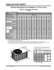
YORK ® Predator ® units are single package air conditioners<br />
with optional gas heating designed for outdoor installation on<br />
a rooftop or slab <strong>and</strong> for non-residential use. These units can<br />
be equipped with factory or field installed electric heaters for<br />
heating applications.<br />
These units are completely assembled on rigid, permanently<br />
attached base rails. All piping, refrigerant charge, <strong>and</strong> electrical<br />
wiring is factory installed <strong>and</strong> tested. The units require<br />
electric power, gas supply (where applicable), <strong>and</strong> duct connections.<br />
The electric heaters have nickel-chrome elements<br />
<strong>and</strong> utilize single-point power connection.<br />
SAFETY CONSIDERATIONS<br />
Should overheating occur, or the gas supply fail to<br />
shut off, shut off the manual gas valve to the furnace<br />
before shutting off the electrical supply.<br />
Do not use this furnace if any part has been under<br />
water. Immediately call a qualified service technician<br />
to inspect the furnace <strong>and</strong> to replace any part of the<br />
control system <strong>and</strong> any gas control which has been<br />
under water.<br />
Due to system pressure, moving parts, <strong>and</strong> electrical components,<br />
installation <strong>and</strong> servicing of air conditioning equipment<br />
can be hazardous. Only qualified, trained service personnel<br />
should install, repair, or service this equipment. Untrained<br />
personnel can perform basic maintenance functions of cleaning<br />
coils <strong>and</strong> filters <strong>and</strong> replacing filters.<br />
Observe all precautions in the literature, labels, <strong>and</strong> tags<br />
accompanying the equipment whenever working on air conditioning<br />
equipment. Be sure to follow all other applicable<br />
safety precautions <strong>and</strong> codes including ANSI Z223.1 or CSA-<br />
B149.1- latest edition.<br />
Wear safety glasses <strong>and</strong> work gloves. Use quenching cloth<br />
<strong>and</strong> have a fire extinguisher available during brazing operations.<br />
If the information in this manual is not followed<br />
exactly, a fire or explosion may result causing property<br />
damage, personal injury or loss of life.<br />
Do not store or use gasoline or other flammable<br />
vapors <strong>and</strong> liquids in the vicinity of this or any other<br />
appliance.<br />
WHAT TO DO IF YOU SMELL GAS:<br />
a. Do not try to light any appliance.<br />
b. Do not touch any electrical switch; do not use<br />
any phone in your building.<br />
c. Immediately call your gas supplier from a neighbor’s<br />
phone. Follow the gas supplier’s instructions.<br />
d. If you cannot reach your gas supplier, call the fire<br />
department.<br />
Installation <strong>and</strong> service must be performed by a<br />
qualified installer, service agency or the gas supplier.<br />
INSPECTION<br />
As soon as a unit is received, it should be inspected for possible<br />
damage during transit. If damage is evident, the extent of<br />
the damage should be noted on the carrier’s freight bill. A<br />
separate request for inspection by the carrier’s agent should<br />
be made in writing.<br />
This furnace is not to be used for temporary heating<br />
of buildings or structures under construction.<br />
Before performing service or maintenance operations<br />
on unit, turn off main power switch to unit. <strong>Electric</strong>al<br />
shock could cause personal injury. Improper<br />
installation, adjustment, alteration, service or maintenance<br />
can cause injury or property damage. Refer<br />
to this manual. For assistance or additional information<br />
consult a qualified installer, service agency or<br />
the gas supplier.<br />
Unitary Products Group 5
REFERENCE<br />
Additional information is available in the following reference<br />
forms:<br />
• Technical Guide - 246699<br />
• General Installation - 127083<br />
• Pre-start & Post-start Check List<br />
• Economizer Accessory -<br />
Downflow Factory Installed<br />
Downflow Field Installed<br />
Horizontal Field Installed<br />
• Motorized Outdoor Air Damper<br />
• Manual Outdoor Air Damper (0-100%)<br />
• Manual Outdoor Air Damper (0-35%)<br />
• <strong>Gas</strong> Heat Propane Conversion Kit<br />
• <strong>Gas</strong> Heat High Altitude Kit (Natural <strong>Gas</strong>)<br />
• <strong>Gas</strong> Heat High Altitude Kit (Propane)<br />
• –60°F <strong>Gas</strong> Heat Kit<br />
• <strong>Electric</strong> Heater Accessory 50” Cabinet<br />
• <strong>Electric</strong> Heater Accessory 42” Cabinet<br />
RENEWAL PARTS<br />
Contact your local York ® parts distribution center for authorized<br />
replacement parts.<br />
APPROVALS<br />
Design certified by CSA as follows:<br />
127083-Y<strong>IM</strong>-B-0606<br />
1. For use as a cooling only unit, cooling unit with supplemental<br />
electric heat or a forced air furnace.<br />
2. For outdoor installation only.<br />
3. For installation on combustible material <strong>and</strong> may be<br />
installed directly on combustible flooring or, in the U.S.,<br />
on wood flooring or Class A, Class B or Class C roof covering<br />
materials.<br />
4. For use with natural gas (convertible to LP with kit).<br />
This product must be installed in strict compliance<br />
with the enclosed installation instructions <strong>and</strong> any<br />
applicable local, state, <strong>and</strong> national codes including,<br />
but not limited to, building, electrical, <strong>and</strong> mechanical<br />
codes.<br />
Incorrect installation may create a condition where the<br />
operation of the product could cause personal injury<br />
or property damage.<br />
The installer should pay particular attention to the words:<br />
NOTE, CAUTION, <strong>and</strong> WARNING. NOTES are intended to<br />
clarify or make the installation easier. CAUTIONS are given<br />
to prevent equipment damage. WARNINGS are given to alert<br />
installer that personal injury <strong>and</strong>/or equipment damage may<br />
result if installation procedure is not h<strong>and</strong>led properly.<br />
6 Unitary Products Group
127083-Y<strong>IM</strong>-B-0606<br />
NOMENCLATURE<br />
Product Category<br />
D = A/C, <strong>Single</strong> Pkg., R-22<br />
Product Identifier<br />
F = 10.4 EER A/C<br />
078 = 6.5 Ton<br />
090 = 7.5 Ton<br />
102 = 8.5 Ton<br />
120 = 10.0 Ton<br />
D F 090 N10 A 2 A AA 3 0 1 2 4 A<br />
Nominal Cooling Capacity<br />
Heat Type <strong>and</strong> Nominal Heat Capacity<br />
C00 = Cooling Only. No heat installed<br />
N10 = 100 MBH Output Aluminized Steel<br />
N15 = 150 MBH Output Aluminized Steel<br />
N20 = 200 MBH Output Aluminized Steel<br />
S10 = 100 MBH Output Stainless Steel<br />
S15 = 150 MBH Output Stainless Steel<br />
S20 = 200 MBH Output Stainless Steel<br />
E09 = 9 KW<br />
E18 = 18 KW<br />
E24 = 24 KW<br />
E36 = 36 KW<br />
E54 = 54 KW<br />
<strong>Gas</strong> Heat Options<br />
<strong>Electric</strong> Heat Options<br />
Airflow<br />
A = Std. Motor<br />
B = Std. Motor/Econo./Barometric Relief (Downflow<br />
Only)<br />
C = Std. Motor/Econo./Power Exhaust (Downflow Only)<br />
D = Std. Motor/Motorized Damper (Downflow Only)<br />
E = Std. Motor/Horizontal Economizer (No Baro.)<br />
F = Std. Motor/Slab Econo./Power Exhaust<br />
(Downflow Only)<br />
G = Std. Motor/Slab Econo./Barometric Relief<br />
(Downflow Only)<br />
N = Hi Static Mtr.<br />
P = Hi Static Mtr./Econo./Barometric Relief<br />
(Downflow Only)<br />
Q = Hi Static Mtr./Econo./Power Exhaust<br />
(Downflow Only)<br />
R = Hi Static Mtr./Motorized Damper (Downflow Only)<br />
S = Hi Static Mtr./Horizontal Economizer (No Baro.)<br />
T = Hi Static Mtr./Slab Econo./Power Exhaust<br />
(Downflow Only)<br />
U = Hi Static Mtr./Slab Econo./Barometric Relief<br />
(Downflow only)<br />
6.5-10.0 Ton York® Model Number Nomenclature<br />
Voltage<br />
2 = 208/230-3-60<br />
4 = 460-3-60<br />
5 = 575-3-60<br />
Installation Options<br />
A = No Options Installed<br />
B=Option1<br />
C=Option2<br />
D = Options 1 & 2<br />
E=Option3<br />
F = Option 4<br />
G = Options 1 & 3<br />
H = Options 1 & 4<br />
J = Options 1, 2 & 3<br />
K = Options 1, 2, & 4<br />
L = Options 1,3 & 4<br />
M=Options1,2,3,&4<br />
N = Options 2 & 3<br />
P = Options 2 & 4<br />
Q = Options 2, 3, & 4<br />
R = Options 3 & 4<br />
S=Option5<br />
T = Options 1 & 5<br />
U = Options 1, 3, & 5<br />
V = Options 1, 4, & 5<br />
W = Options 1, 3, 4, & 5<br />
X = Options 3 & 5<br />
Y = Options 4 & 5<br />
Z = Options 3, 4 & 5<br />
Options<br />
Product Generation<br />
3 = Third Generation<br />
4 = Fourth Generation<br />
1 = Disconnect<br />
2 = Non-Pwr'd Conv. Outlet<br />
3 = Smoke Detector S.A.<br />
4 = Smoke Detector R.A.<br />
5=Pwr'dConv.Outlet<br />
Product Style<br />
A = Style A<br />
B = Style B<br />
C = Style C<br />
Configuration Options (not required for all units)<br />
These four digits will not be assigned until a quote is requested, or an order placed.<br />
SS Drain Pan<br />
CPC Controller, DFS, APS<br />
Johnson Controller, DFS, APS<br />
Honeywell Controller, DFS, APS<br />
Novar Controller, DFS, APS<br />
Simplicity IntelliComfort Controller<br />
Simplicity IntelliComfort Controller w/ModLinc<br />
2" Pleated filters<br />
BAS Ready Unit with Belimo Economizer<br />
Shipping Bag<br />
Any Combination of Additional Options that Don’t Have an Option Code Pre-assigned<br />
AA = None<br />
AB = Phase Monitor<br />
<strong>AC</strong> = Coil Guard<br />
AD = Dirty Filter Switch<br />
AE = Phase Monitor & Coil Guard<br />
AF = Phase Monitor & Dirty Filter Switch<br />
AG = Coil Guard & Dirty Filter Switch<br />
AH = Phase Monitor, Coil Guard & Dirty Filter Switch<br />
Additional Options<br />
RC = Coil Guard, Shipping Bag & American Flag<br />
TA = Technicoat Condenser Coil<br />
TJ = Technicoat Evaporator Coil<br />
TS = Technicoat Evaporator & Condenser Coils<br />
ZZ = If desired option combination is not listed above, ZZ will be assigned <strong>and</strong> configuration options will be<br />
located in digits 15-18.<br />
Unitary Products Group 7
INSTALLATION<br />
INSTALLATION SAFETY INFORMATION<br />
Read these instructions before continuing this appliance<br />
installation. This is an outdoor combination heating <strong>and</strong> cooling<br />
unit. The installer must assure that these instructions are<br />
made available to the consumer <strong>and</strong> with instructions to<br />
retain them for future reference.<br />
1. Refer to the furnace rating plate for the approved type of<br />
gas for this furnace.<br />
2. Install this furnace only in a location <strong>and</strong> position as<br />
specified on Page 10 of these instructions.<br />
3. Never test for gas leaks with an open flame. Use commercially<br />
available soap solution made specifically for<br />
the detection of leaks when checking all connections, as<br />
specified on Pages 8, 26, 27 <strong>and</strong> 54 of these instructions.<br />
4. Always install furnace to operate within the furnace's<br />
intended temperature-rise range with the duct system<br />
<strong>and</strong> within the allowable external static pressure range,<br />
as specified on the unit name/rating plate, specified on<br />
Page 56 of these instructions.<br />
5. This equipment is not to be used for temporary heating<br />
of buildings or structures under construction.<br />
FIRE OR EXPLOSION HAZARD<br />
Failure to follow the safety warning exactly could<br />
result in serious injury, death or property damage.<br />
Never test for gas leaks with an open flame. use a<br />
commercially available soap solution made specifically<br />
for the detection of leaks to check all connections.<br />
A fire or explosion may result causing property<br />
damage, personal injury or loss of life.<br />
PRECEDING INSTALLATION<br />
1. Remove the two screws holding the brackets in the front,<br />
rear <strong>and</strong> compressor side fork-lift slots.<br />
Bracket<br />
Screws<br />
Turn down<br />
FIGURE 1 - UNIT SHIPPING BR<strong>AC</strong>KET<br />
127083-Y<strong>IM</strong>-B-0606<br />
2. Turn each bracket toward the ground <strong>and</strong> the protective<br />
plywood covering will drop to the ground.<br />
3. Remove the condenser coil external protective covering<br />
prior to operation.<br />
4. Remove the toolless doorknobs <strong>and</strong> instruction packet<br />
prior to installation.<br />
Condenser<br />
Coil External<br />
Protective<br />
Covering<br />
Barometric<br />
Relief Hood in<br />
Shipping Location<br />
(if included)<br />
FIGURE 2 - CONDENSER COVERING<br />
Toolless<br />
Doorknobs<br />
Installation<br />
Instruction<br />
Packet<br />
FIGURE 3 - COMPRESSOR SECTION<br />
8 Unitary Products Group
127083-Y<strong>IM</strong>-B-0606<br />
This product must be installed in strict compliance with<br />
the enclosed installation instructions <strong>and</strong> any applicable<br />
local, state <strong>and</strong> national codes including, but not<br />
limited to, building, electrical, <strong>and</strong> mechanical codes.<br />
The furnace <strong>and</strong> its individual shut-off valve must be<br />
disconnected from the gas supply piping system during<br />
any pressure testing at pressures in excess of 1/2<br />
PSIG.<br />
Pressures greater than 1/2 PSIG will cause gas valve<br />
damage resulting in a hazardous condition. If it is subjected<br />
to a pressure greater than 1/2 PSIG, the gas<br />
valve must be replaced.<br />
The furnace must be isolated from the gas supply piping<br />
system by closing its individual manual shut-off<br />
valve during any pressure testing of the gas supply piping<br />
system at test pressures equal to or less than 1/2<br />
PSIG.<br />
L<strong>IM</strong>ITATIONS<br />
These units must be installed in accordance with the following:<br />
In U.S.A.:<br />
1. National <strong>Electric</strong>al Code, ANSI/NFPA No. 70 - Latest<br />
Edition<br />
2. National Fuel <strong>Gas</strong> Code, ANSI Z223.1 - Latest Edition<br />
3. <strong>Gas</strong>-Fired Central Furnace St<strong>and</strong>ard, ANSI Z21.47a. -<br />
Latest Edition<br />
4. Local building codes, <strong>and</strong><br />
5. Local gas utility requirements<br />
In Canada:<br />
1. Canadian <strong>Electric</strong>al Code, CSA C22.1<br />
2. Installation Codes, CSA - B149.1.<br />
3. Local plumbing <strong>and</strong> waste water codes, <strong>and</strong><br />
4. Other applicable local codes.<br />
Refer to Tables 1 & 2 for unit application data.<br />
After installation, gas fired units must be adjusted to obtain a<br />
temperature rise within the range specified on the unit rating<br />
plate.<br />
If components are to be added to a unit to meet local codes,<br />
they are to be installed at the dealer’s <strong>and</strong>/or customer’s<br />
expense.<br />
Size of unit for proposed installation should be based on heat<br />
loss/heat gain calculation made according to the methods of<br />
Air Conditioning Contractors of America (<strong>AC</strong>CA).<br />
This furnace is not to be used for temporary heating of buildings<br />
or structures under construction.<br />
Unitary Products Group 9
Terminal Block<br />
for Hi-Voltage<br />
Connection<br />
Second model<br />
nameplate inside<br />
hinged access<br />
panel<br />
Dual stage<br />
cooling for<br />
maximum<br />
comfort<br />
Compressor #2<br />
Access (High-<br />
Eff Compressor<br />
w/ crankcase<br />
heater)<br />
Base Rails w/ Forklift<br />
Slots (3 Sides) & Lifting<br />
Holes<br />
Roof curbs in eight- <strong>and</strong><br />
fourteen-inch heights.<br />
Rood curbs for transitioning<br />
from Sunline footprint<br />
to the DM/DH/DF Series<br />
footprint are also available<br />
(field-installed<br />
accessory)<br />
Simplicity® Control Board<br />
w/Screw Connector for<br />
T-stat Wiring <strong>and</strong> Network<br />
Connection<br />
Toolless<br />
door latch<br />
Side entry power<br />
<strong>and</strong> control wiring<br />
knockouts<br />
Disconnect Location<br />
(Optional Disconnect Switch)<br />
FIGURE 4 - PREDATOR ® COMPONENT LOCATION (DF120 SHOWN)<br />
TABLE 1: UNIT VOLTAGE L<strong>IM</strong>ITATIONS<br />
Power Rating1 Minimum Maximum<br />
208/230-3-60 187 252<br />
460-3-60 432 504<br />
575-3-60 540 630<br />
1. Utilization range “A” in accordance with ARI St<strong>and</strong>ard 110.<br />
TABLE 2: UNIT TEMPERATURE L<strong>IM</strong>ITATIONS<br />
Temperature Min. Max.<br />
Wet Bulb Temperature (°F) of Air on<br />
Evaporator Coil<br />
Dry Bulb Temperature (°F) of Air on<br />
Condenser Coil<br />
1.<br />
57 72<br />
A low ambient accessory is available for operation<br />
down to -20°F.<br />
0 1<br />
125<br />
LOCATION<br />
Filter Access<br />
(2” Filters)<br />
Slide-Out Drain Pan<br />
w/ Steel 3/4” NPT,<br />
Female Connection<br />
Compressor #1 Access (High-Eff<br />
Compressor w/ crankcase heater)<br />
127083-Y<strong>IM</strong>-B-0606<br />
Use the following guidelines to select a suitable location for<br />
these units:<br />
1. Unit is designed for outdoor installation only.<br />
2. Condenser coils must have an unlimited supply of air.<br />
Where a choice of location is possible, position the unit<br />
on either north or east side of building.<br />
3. Suitable for mounting on roof curb.<br />
Filter-Drier (Solid Core)<br />
Condenser<br />
Section<br />
Belt-Drive<br />
Blower<br />
Motor<br />
Slide-out motor<br />
<strong>and</strong> blower<br />
assembly for<br />
ease of adjustment<br />
<strong>and</strong> service<br />
Power Ventor Motor<br />
Two-stage gas heating<br />
to maintain<br />
warm, comfortable<br />
temperature<br />
Intelligent control board for<br />
safe <strong>and</strong> efficient operation<br />
4. Roof structures must be able to support the weight of the<br />
unit <strong>and</strong> its options/accessories. Unit must be installed<br />
on a solid, level roof curb or appropriate angle iron<br />
frame.<br />
5. Maintain level tolerance to 1/2” across the entire width<br />
<strong>and</strong> length of unit.<br />
10 Unitary Products Group
127083-Y<strong>IM</strong>-B-0606<br />
Excessive exposure of this furnace to contaminated<br />
combustion air may result in equipment damage or<br />
personal injury. Typical contaminates include: permanent<br />
wave solution, chlorinated waxes <strong>and</strong> cleaners,<br />
chlorine based swimming pool chemicals, water<br />
softening chemicals, carbon tetrachloride, Halogen<br />
type refrigerants, cleaning solvents (e.g. perchloroethylene),<br />
printing inks, paint removers, varnishes,<br />
hydrochloric acid, cements <strong>and</strong> glues, antistatic fabric<br />
softeners for clothes dryers, masonry acid washing<br />
materials.<br />
RIGGING AND HANDLING<br />
Exercise care when moving the unit. Do not remove any<br />
packaging until the unit is near the place of installation. Rig<br />
the unit by attaching chain or cable slings to the lifting holes<br />
provided in the base rails. Spreader bars, whose length<br />
exceeds the largest dimension across the unit, MUST be<br />
used across the top of the unit.<br />
If a unit is to be installed on a roof curb other than a<br />
YORK roof curb, gasketing must be applied to all<br />
surfaces that come in contact with the unit underside.<br />
Before lifting, make sure the unit weight is distributed<br />
equally on the rigging cables so it will lift evenly.<br />
<strong>Units</strong> may be moved or lifted with a forklift. Slotted openings<br />
in the base rails are provided for this purpose.<br />
LENGTH OF FORKS MUST BE A MIN<strong>IM</strong>UM OF 60<br />
INCHES.<br />
All panels must be secured in place when the unit is<br />
lifted.<br />
The condenser coils should be protected from rigging<br />
cable damage with plywood or other suitable<br />
material.<br />
TABLE 3: UNIT WEIGHT<br />
Unitary Products Group 11<br />
Model<br />
Shipping 1<br />
Weight (lbs.)<br />
1. Weights include largest heating option.<br />
2.<br />
8 tube gas section.<br />
3. 54kW heater.<br />
Operating<br />
Weight (lbs.)<br />
DF078 1058 1053<br />
DF090 875 870<br />
DF102 888 883<br />
DF120 1190 1185<br />
ECON. 85 84<br />
PE 150 148<br />
GAS HEAT 2<br />
110 100<br />
ELEC. HEAT3 49 49<br />
FIGURE 5 - UNIT 4 POINT LOAD<br />
TABLE 4: 4 POINT LOAD WEIGHT<br />
Model<br />
)<br />
- . 6<br />
Location (lbs.) 1<br />
A B C D<br />
DF078 231 197 288 337<br />
DF090 195 146 228 306<br />
DF102 197 147 230 309<br />
DF120 260 222 324 379<br />
1. Weights include largest heating option.<br />
TABLE 5: 6 POINT LOAD WEIGHT<br />
,<br />
Location (lbs.)<br />
Model<br />
A B C D E F<br />
DF078 158 142 128 187 207 231<br />
DF090 137 112 93 145 175 214<br />
DF102 138 113 93 146 175 216<br />
DF120 178 160 144 210 233 260<br />
*<br />
. 4 6<br />
+
)<br />
- . 6<br />
FIGURE 6 - UNIT 6 POINT LOAD<br />
LEFT<br />
X<br />
*<br />
Unit Model Number X Y<br />
DF078 47 1/2 25 1/2<br />
DF090 38 23<br />
DF102 38 23<br />
DF120 47 1/2 25 1/2<br />
FIGURE 7 - UNIT CENTER OF GRAVITY<br />
CLEARANCES<br />
.<br />
All units require particular clearances for proper operation<br />
<strong>and</strong> service. Installer must make provisions for adequate<br />
combustion <strong>and</strong> ventilation air in accordance with section 5.3<br />
of Air for Combustion <strong>and</strong> Ventilation of the National Fuel <strong>Gas</strong><br />
Code, ANSI Z223.1 – Latest Edition (in U.S.A.), or Sections<br />
7.2, 7.3, or 7.4 of <strong>Gas</strong> Installation Codes, CSA-B149.1 (in<br />
Canada) - Latest Edition, <strong>and</strong>/or applicable provisions of the<br />
local building codes. Refer to Table 7 for clearances required<br />
+<br />
Y<br />
-<br />
FRONT<br />
. 4 6<br />
,<br />
127083-Y<strong>IM</strong>-B-0606<br />
for combustible construction, servicing, <strong>and</strong> proper unit operation.<br />
Do not permit overhanging structures or shrubs to<br />
obstruct condenser air discharge outlet, combustion<br />
air inlet or vent outlets.<br />
Excessive exposure to contaminated combustion air<br />
will result in safety <strong>and</strong> performance related problems.<br />
To maintain combustion air quality, the recommended<br />
source of combustion air is the outdoor air<br />
supply. The outdoor air supplied for combustion<br />
should be free from contaminants due to chemical<br />
exposure that may be present from the following<br />
sources.<br />
• Commercial buildings<br />
• Indoor pools<br />
• Laundry rooms<br />
• Hobby or craft rooms<br />
• Chemical storage areas<br />
The following substances should be avoided to<br />
maintain outdoor combustion air quality.<br />
• Permanent wave solutions<br />
• Chlorinated waxes <strong>and</strong> cleaners<br />
• Chlorine based swimming pool cleaners<br />
• Water softening chemicals<br />
• De-icing salts or chemicals<br />
• Carbon tetrachloride<br />
• Halogen type refrigerants<br />
• Cleaning solvents (such as perchloroethylene)<br />
• Printing inks, paint removers, varnishes, etc.<br />
• Hydrochloric acid<br />
• Cements <strong>and</strong> glues<br />
• Anti-static fabric softeners for clothes dryers<br />
• Masonry acid washing materials<br />
12 Unitary Products Group
127083-Y<strong>IM</strong>-B-0606<br />
4-1/4<br />
30-11/32<br />
FIGURE 8 - UNIT D<strong>IM</strong>ENSIONS<br />
X<br />
LEFT<br />
59<br />
Power<br />
Entry<br />
Ø 2-1/2<br />
30-3/16<br />
17-3/16<br />
24-3/16 6-3/16<br />
TABLE 6: UNIT HEIGHT<br />
Unit Model Number X<br />
DF078 50 3/4<br />
DF090 42<br />
DF102 42<br />
DF120 50 3/4<br />
TABLE 7: UNIT CLEARANCES<br />
Top 1<br />
Front 2<br />
Rear 3<br />
1. <strong>Units</strong> must be installed outdoors. Overhanging structure<br />
or shrubs should not obstruct condenser air discharge<br />
outlet.<br />
2. The products of combustion must not be allowed to<br />
accumulate within a confined space <strong>and</strong> re-circulate.<br />
3. To remove the slide-out drain pan, a rear clearance of<br />
sixty inches is required. If space is unavailable, the<br />
drain pan can be removed through the front by separating<br />
the corner wall.<br />
4. <strong>Units</strong> may be installed on combustible floors made from<br />
wood or class A, B or C roof covering materials.<br />
DETAIL A<br />
# "<br />
72” Right 12”<br />
36” Left 36”<br />
36” Bottom 4<br />
/ = I 2 EF A 1 A J<br />
% ! $<br />
8 EA M B 9 = ) ? H I I BH + E<br />
* = I A<br />
2 = <br />
0”<br />
Control<br />
Entry<br />
Ø 7/8<br />
Power<br />
Entry<br />
Ø 2-1/2<br />
Convenience<br />
Power<br />
Outlet<br />
Entry<br />
Ø 7/8<br />
27<br />
For Drain<br />
Dimensions<br />
See Detail C<br />
89<br />
See Detail<br />
A<br />
For Baserail<br />
Dimensions<br />
See Detail B<br />
NOTE: A one-inch clearance must be provided between<br />
any combustible material <strong>and</strong> the supply ductwork<br />
for a distance of 3 feet from the unit.<br />
DETAIL B<br />
DETAIL C<br />
NOTE: If the unit includes gas heating, locate the unit so<br />
the flue exhaust is at least:<br />
• Three (3) feet above any forced air inlet located within 10<br />
horizontal feet (excluding those integral to the unit).<br />
• Four (4) feet below, four (4) horizontal feet from, or one<br />
(1) foot above any door or gravity air inlet into the building.<br />
• Four (4) feet from electric meters, gas meters, regulators,<br />
<strong>and</strong> relief equipment.<br />
Unitary Products Group 13<br />
FRONT<br />
# ! &<br />
! ! "<br />
! &<br />
11-1/2<br />
! ' $
.<br />
21-3/16<br />
19-3/16<br />
17-3/16<br />
6-13/16<br />
14-<br />
23/32<br />
16-3/8<br />
18-1/16<br />
19-5/8<br />
63-1/2<br />
FIGURE 9 - BOTTOM DUCT OPENINGS (FROM ABOVE)<br />
REAR DUCT D<strong>IM</strong>ENSIONS<br />
LEFT<br />
7-1/8<br />
CABINET SIZE<br />
“A”<br />
D<strong>IM</strong>ENSION<br />
“B” “C”<br />
50 3/4” 28 1/4 18 1/16 28 1/4<br />
42” 27 3/4 12 1/16 27 1/2<br />
FIGURE 10 - REAR DUCT D<strong>IM</strong>ENSIONS<br />
32-11/16<br />
18<br />
6-13/16<br />
Return<br />
Air<br />
18-1/4<br />
27-1/2<br />
5-5/32<br />
FRONT<br />
Bottom<br />
Condensate<br />
Entry<br />
127083-Y<strong>IM</strong>-B-0606<br />
14 Unitary Products Group<br />
Supply<br />
Air<br />
21<br />
24<br />
6-13/16<br />
Bottom<br />
Power, Control<br />
<strong>and</strong><br />
Convenience<br />
Outlet Wiring<br />
Entries<br />
Bottom <strong>Gas</strong><br />
Supply Entry<br />
Supply<br />
Air<br />
C<br />
Dot Plugs<br />
12-15/16<br />
Return<br />
Air<br />
18-1/4<br />
2-31/32<br />
31-11/16<br />
A<br />
B
127083-Y<strong>IM</strong>-B-0606<br />
DUCTWORK<br />
Ductwork should be designed <strong>and</strong> sized according to the<br />
methods in Manual D of the Air Conditioning Contractors of<br />
America (<strong>AC</strong>CA) or as recommended by any other recognized<br />
authority such as ASHRAE or SM<strong>AC</strong>NA.<br />
A closed return duct system should be used. This will not<br />
preclude use of economizers or outdoor fresh air intake. The<br />
supply <strong>and</strong> return air duct connections at the unit should be<br />
made with flexible joints to minimize noise.<br />
The supply <strong>and</strong> return air duct systems should be designed<br />
for the CFM <strong>and</strong> static pressure requirements of the job. They<br />
should NOT be sized to match the dimensions of the duct<br />
connections on the unit.<br />
Refer to Figure 9 for bottom air duct openings. Refer to Figure<br />
10 for rear air duct openings.<br />
6 ; 2 <br />
# <br />
!<br />
FIGURE 11 - PREDATOR ® ROOF CURB D<strong>IM</strong>ENSIONS<br />
$<br />
& # &<br />
% $ # &<br />
4 - 6 7 4 <br />
5 7 2 2 ;<br />
& H "<br />
DUCT COVERS<br />
<strong>Units</strong> are shipped with the side duct openings covered <strong>and</strong> a<br />
covering over the bottom of the unit. For bottom duct application,<br />
no duct cover changes are necessary. For side duct<br />
application, remove the side duct covers <strong>and</strong> install over the<br />
bottom duct openings. The panels removed from the side<br />
duct connections are designed to be reused by securing each<br />
panel to its respective downflow opening. But keep in mind<br />
that the supply panel is installed with the painted surface UP,<br />
facing the heat exchanger, while the return panel is installed<br />
with the painted surface DOWN, facing the downflow duct<br />
opening. The supply panel is secured with the bracket<br />
(already in place from the factory) <strong>and</strong> two screws. It’s a snug<br />
fit for the panel when sliding it between the heat exchanger<br />
<strong>and</strong> unit bottom, but there is room. The return panel is<br />
secured with four screws.<br />
1 5 7 ) 6 - , , - + 7 , - 4<br />
+ 2 4 - 5 5 4 5 - + 6 1 <br />
1 5 7 ) 6 - , , - + 7 , - 4<br />
+ , - 5 - 4 5 - + 6 1 <br />
Unitary Products Group 15<br />
. 4 6<br />
FIGURE 12 - SUNLINE TO PREDATOR ® TRANSITION ROOF CURBS<br />
# <br />
' "<br />
! <br />
4 - 6 7 4 <br />
6 ; 2<br />
! "<br />
5 7 2 2 ;<br />
4 1/ 0 6<br />
$ & # &<br />
# ' "<br />
. 4 6 4 1/ 0 6<br />
$ " "
When fastening ductwork to side duct flanges on<br />
unit, insert screws through duct flanges only. DO<br />
NOT insert screws through casing. Outdoor ductwork<br />
must be insulated <strong>and</strong> water-proofed.<br />
FIGURE 13 - SIDE PANELS WITH HOLE PLUGS<br />
Note orientation. Panel is “insulation” side up.<br />
FIGURE 14 - RETURN DOWNFLOW PLENUM WITH<br />
PANEL<br />
FIGURE 15 - DISCHARGE PANEL IN PL<strong>AC</strong>E<br />
CONDENSATE DRAIN<br />
127083-Y<strong>IM</strong>-B-0606<br />
The side condensate drain is reversible <strong>and</strong> maybe re-oriented<br />
to the rear of the cabinet to facilitate condensate piping.<br />
A condensate drain connection is available through the<br />
base pan for piping inside the roof curb. Trap the connection<br />
per Figure 16. The trap <strong>and</strong> drain lines should be protected<br />
from freezing.<br />
Plumbing must conform to local codes. Use a sealing compound<br />
on male pipe threads. Install condensate drain line<br />
from the 3/4 inch NPT female connection on the unit to an<br />
open drain.<br />
COMPRESSORS<br />
The compressors are mounted on elastomer insulators. The<br />
mounting bolts have been fully tightened for shipping.<br />
FILTERS<br />
! E E K <br />
2 6 1 ) + 1<br />
/ 7 ) 4 ,<br />
FIGURE 16 - CONDENSATE DRAIN<br />
Do not loosen the compressor mounting bolts.<br />
Two-inch filters are supplied with each unit. One-inch filters<br />
may be used with no modification to the filter racks. Filters<br />
must always be installed ahead of evaporator coil <strong>and</strong> must<br />
be kept clean or replaced with same size <strong>and</strong> type. Dirty filters<br />
reduce the capacity of the unit <strong>and</strong> result in frosted coils<br />
or safety shutdown. Refer to Physical Data tables for the<br />
number <strong>and</strong> size of filters needed for the unit. The unit should<br />
not be operated without filters properly installed.<br />
Make sure that panel latches are properly positioned<br />
on the unit to maintain an airtight seal.<br />
16 Unitary Products Group
127083-Y<strong>IM</strong>-B-0606<br />
THERMOSTAT WIRING<br />
The thermostat should be located on an inside wall approximately<br />
56 inch above the floor where it will not be subject to<br />
drafts, sun exposure or heat from electrical fixtures or appliances.<br />
Follow the manufacturer's instructions enclosed with<br />
thermostat for general installation procedure. Seven (7) colorcoded,<br />
insulated wires should be used to connect the thermostat<br />
to the unit. Refer to Table 8 for control wire sizing <strong>and</strong><br />
maximum length.<br />
TABLE 8: CONTROL WIRE SIZES<br />
Wire Size Maximum Length 1<br />
18 AWG 150 Feet<br />
1. From the unit to the thermostat <strong>and</strong> back to the unit.<br />
POWER AND CONTROL WIRING<br />
Field wiring to the unit, fuses, <strong>and</strong> disconnects must conform<br />
to provisions of National <strong>Electric</strong>al Code (NEC), ANSI/NFPA<br />
No. 70 – Latest Edition (in U.S.A.), current Canadian <strong>Electric</strong>al<br />
Code C221, <strong>and</strong>/or local ordinances. The unit must be<br />
electrically grounded in accordance with NEC <strong>and</strong> CEC as<br />
specified above <strong>and</strong>/or local codes.<br />
Voltage tolerances which must be maintained at the compressor<br />
terminals during starting <strong>and</strong> running conditions are<br />
indicated on the unit Rating Plate <strong>and</strong> Table 1.<br />
The internal wiring harnesses furnished with this unit are an<br />
integral part of the design certified unit. Field alteration to<br />
comply with electrical codes should not be required. If any of<br />
the wire supplied with the unit must be replaced, replacement<br />
wire must be of the type shown on the wiring diagram <strong>and</strong> the<br />
same minimum gauge as the replaced wire.<br />
A disconnect must be utilized for these units. Factory<br />
installed disconnects are available. If installing a disconnect<br />
(field supplied or York International ® supplied accessory),<br />
refer to Figure 4 for the recommended mounting location.<br />
Avoid damage to internal components if drilling<br />
holes for disconnect mounting.<br />
NOTE: Since not all local codes allow the mounting of a disconnect<br />
on the unit, please confirm compliance with<br />
local code before mounting a disconnect on the unit.<br />
<strong>Electric</strong>al line must be sized properly to carry the load. USE<br />
COPPER CONDUCTORS ONLY. Each unit must be wired<br />
with a separate branch circuit fed directly from the meter<br />
panel <strong>and</strong> properly fused.<br />
Refer to Figures 17, 18 <strong>and</strong> 19 for typical field wiring <strong>and</strong> to<br />
the appropriate unit wiring diagram mounted inside control<br />
doors for control circuit <strong>and</strong> power wiring information.<br />
When connecting electrical power <strong>and</strong> control wiring<br />
to the unit, water-proof connectors must be used so<br />
that water or moisture cannot be drawn into the unit<br />
during normal operation. The above water-proofing<br />
conditions will also apply when installing a field supplied<br />
disconnect switch.<br />
POWER WIRING DETAIL<br />
<strong>Units</strong> are factory wired for the voltage shown on the unit<br />
nameplate. Refer to <strong>Electric</strong>al Data Tables 9 to 16 to size<br />
power wiring, fuses, <strong>and</strong> disconnect switch.<br />
Power wiring is brought into the unit through the side of the<br />
unit or the basepan inside the curb.<br />
Unitary Products Group 17
FIGURE 17 - ELECTRONIC THERMOSTAT FIELD WIRING<br />
6 5 6 ) 6<br />
9<br />
9<br />
;<br />
;<br />
/<br />
+<br />
4 0<br />
4 +<br />
6 0 - 4 5 6 ) 6<br />
6 - 4 1 ) 5<br />
4 +<br />
4 0<br />
9<br />
9<br />
;<br />
;<br />
:<br />
/<br />
+<br />
: !<br />
: "<br />
)<br />
)<br />
6<br />
6<br />
6 4 - 6 - 5 - 5 4<br />
- 6 " % ! " 1. 7 5 - ,<br />
7 16 6 - 4 1 ) 5<br />
5 6 4 12 6 *<br />
127083-Y<strong>IM</strong>-B-0606<br />
18 Unitary Products Group<br />
9<br />
9<br />
;<br />
;<br />
4<br />
/<br />
+<br />
:<br />
+ +<br />
" 8 J<br />
6 H= I B H A H<br />
- A ? JH E? F H C H= = > A 6 D A H I J= J - 6 % % " E ? K @ A I I K > > = I A <br />
6 A H E = I ) = @ ) F H L E@ A = HA = O K JF K J J ? I A JD A K J@ H<br />
A ? E A H @ = F A HI M D A JD A JD A H I J= J I M EJ? D A I J JD A I A J> = ? F I EJE <br />
FIGURE 18 - FIELD WIRING 24 VOLT THERMOSTAT<br />
9<br />
9<br />
;<br />
/<br />
+ +<br />
4 - 6 -<br />
1 2 5<br />
;<br />
:<br />
4<br />
5 ,<br />
+<br />
7 16 + 6 4 <br />
* ) 4 ,
127083-Y<strong>IM</strong>-B-0606<br />
GROUND<br />
LUG<br />
TERMINAL BLOCK TB1<br />
F<strong>AC</strong>TORY OR FIELD<br />
SUPPLIED DISCONNECT<br />
FIGURE 19 - FIELD WIRING DISCONNECT - COOLING UNIT WITH/WITHOUT ELECTRIC HEAT<br />
GROUND<br />
LUG<br />
CONT<strong>AC</strong>TOR 1M<br />
T1<br />
L1<br />
T2 T3<br />
FIGURE 20 - FIELD WIRING DISCONNECT - COOLING UNIT WITH GAS HEAT<br />
L2<br />
L3<br />
F<strong>AC</strong>TORY OR FIELD<br />
SUPPLIED DISCONNECT<br />
THREE<br />
PHASE<br />
POWER<br />
SUPPLY<br />
THREE<br />
PHASE<br />
POWER<br />
SUPPLY<br />
Unitary Products Group 19
TABLE 9: ELECTRICAL DATA - DF078 (6-1/2 TON) MID EFFICIENCY W/O PWRD CONV. OUTLET<br />
TABLE 10: ELECTRICAL DATA - DF078 (6-1/2 TON) MID EFFICIENCY W/PWRD CONV. OUTLET<br />
127083-Y<strong>IM</strong>-B-0606<br />
Voltage<br />
Compressors<br />
OD Fan<br />
Motors<br />
Supply<br />
Blower<br />
Motor FLA<br />
Pwr<br />
Exh<br />
Motor<br />
Pwr<br />
Conv<br />
Outlet<br />
<strong>Electric</strong> Heater Actual<br />
Model No. KW<br />
Heater<br />
Amps<br />
Min. Circuit<br />
Ampacity<br />
(Amps)<br />
MCA<br />
w/Power<br />
Exhaust<br />
(Amps)<br />
Max<br />
Fuse*<br />
Size<br />
(Amps)<br />
Max Fuse* Size<br />
w/Power<br />
Exhaust<br />
(Amps)<br />
RLA<br />
ea.<br />
LRA<br />
ea.<br />
FLA<br />
ea.<br />
1.5<br />
HP<br />
2<br />
HP<br />
FLA FLA<br />
1.5<br />
HP<br />
2<br />
HP<br />
1.5<br />
HP<br />
2<br />
HP<br />
1.5<br />
HP<br />
2<br />
HP<br />
1.5<br />
HP<br />
2<br />
HP<br />
None -- -- 33.1 35.1 38.6 40.6 40 45 45 50<br />
2TP04520925 6.8 18.9 33.1 35.1 38.6 40.7 40 45 45 50<br />
208 10.6 78.0 1.5 6.2 8.2 5.5 0.0 2TP04521825 13.5 37.5 54.6 57.1 61.5 64.0 60 60 70 70<br />
2TP04522425 18.0 50.0 70.2 72.7 77.1 79.6 80 80 80 80<br />
2TP04523625 25.5 70.8 96.2 98.7 103.1 105.6 100 100 110 110<br />
None -- -- 33.1 35.1 38.6 40.6 40 45 45 50<br />
2TP04520925 9.0 21.7 34.8 37.3 41.7 44.2 40 45 45 50<br />
230 10.6 78.0 1.5 6.2 8.2 5.5 0.0 2TP04521825 18.0 43.3 61.9 64.4 68.8 71.3 70 70 70 80<br />
2TP04522425 24.0 57.7 79.9 82.4 86.8 89.3 80 90 90 90<br />
2TP04523625 34.0 81.8 110.0 112.5 116.9 119.4 110 125 125 125<br />
None -- -- 16.4 17.4 18.6 19.6 20 20 20 20<br />
2TP04520946 9 11.3 17.4 18.7 20.2 21.4 20 20 25 25<br />
460 5.2 40.0 0.8 3.1 4.1 2.2 0.0 2TP04521846 18 22.6 30.9 32.2 33.7 34.9 35 35 35 35<br />
2TP04522446 24 30.1 40 41.2 42.7 44 40 45 45 45<br />
2TP04523646 34 42.7 55 56.2 57.7 59 60 60 60 60<br />
None -- -- 12.8 14 14.6 15.8 15 15 15 20<br />
2TP04520958 9 9.0 13.8 15.3 16.1 17.6 15 20 20 20<br />
575 4.1 32.0 0.6 2.4 3.6 1.8 0.0 2TP04521858 18 18.1 24.7 26.2 26.9 28.4 25 30 30 30<br />
2TP04522458 24 24.1 31.9 33.4 34.1 35.6 35 35 35 40<br />
2TP04523658 34 34.1 43.9 45.4 46.1 47.6 45 50 50 50<br />
* Maximum H<strong>AC</strong>R breaker of the same AMP size is applicable.<br />
Voltage<br />
Compressors<br />
OD Fan<br />
Motors<br />
Supply<br />
Blower<br />
Motor FLA<br />
Pwr<br />
Exh<br />
Motor<br />
Pwr<br />
Conv<br />
Outlet<br />
<strong>Electric</strong> Heater Actual<br />
Model No. KW<br />
Heater<br />
Amps<br />
Min. Circuit<br />
Ampacity<br />
(Amps)<br />
MCA<br />
w/Power<br />
Exhaust<br />
(Amps)<br />
Max<br />
Fuse*<br />
Size<br />
(Amps)<br />
Max Fuse* Size<br />
w/Power<br />
Exhaust<br />
(Amps)<br />
RLA<br />
ea.<br />
LRA<br />
ea.<br />
FLA<br />
ea.<br />
1.5<br />
HP<br />
2<br />
HP<br />
FLA FLA<br />
1.5<br />
HP<br />
2<br />
HP<br />
1.5<br />
HP<br />
2<br />
HP<br />
1.5<br />
HP<br />
2<br />
HP<br />
1.5<br />
HP<br />
2<br />
HP<br />
None -- -- 43.1 45.1 48.6 50.6 50 50 50 60<br />
2TP04520925 6.8 18.9 43.8 46.3 50.7 53.2 50 50 60 60<br />
208 10.6 78.0 1.5 6.2 8.2 5.5 10.0 2TP04521825 13.5 37.5 67.1 69.6 74.0 76.5 70 70 80 80<br />
2TP04522425 18.0 50.0 82.7 85.2 89.6 92.1 90 90 90 100<br />
2TP04523625 25.5 70.8 108.7 111.2 115.6 118.1 110 125 125 125<br />
None -- -- 43.1 45.1 48.6 50.6 50 50 50 60<br />
2TP04520925 9.0 21.7 47.3 49.8 54.2 56.7 50 50 60 60<br />
230 10.6 78.0 1.5 6.2 8.2 5.5 10.0 2TP04521825 18.0 43.3 74.4 76.9 81.3 83.8 80 80 90 90<br />
2TP04522425 24.0 57.7 92.4 94.9 99.3 101.8 100 100 100 110<br />
2TP04523625 34.0 81.8 122.5 125.0 129.4 131.9 125 125 150 150<br />
None -- -- 21.4 22.4 23.6 24.6 25 25 25 25<br />
2TP04520946 9 11.3 23.7 24.9 26.4 27.7 25 25 30 30<br />
460 5.2 40.0 0.8 3.1 4.1 2.2 5.0 2TP04521846 18 22.6 37.2 38.4 39.9 41.2 40 40 40 45<br />
2TP04522446 24 30.1 46.2 47.5 49 50.2 50 50 50 60<br />
2TP04523646 34 42.7 61.2 62.5 64 65.2 70 70 70 70<br />
None -- -- 16.8 18 18.6 19.8 20 20 20 20<br />
2TP04520958 9 9.0 18.8 20.3 21.1 22.6 20 25 25 25<br />
575 4.1 32.0 0.6 2.4 3.6 1.8 4.0 2TP04521858 18 18.1 29.7 31.2 31.9 33.4 30 35 35 35<br />
2TP04522458 24 24.1 36.9 38.4 39.1 40.6 40 40 40 45<br />
2TP04523658 34 34.1 48.9 50.4 51.1 52.6 50 60 60 60<br />
* Maximum H<strong>AC</strong>R breaker of the same AMP size is applicable.<br />
20 Unitary Products Group
127083-Y<strong>IM</strong>-B-0606<br />
TABLE 11: ELECTRICAL DATA - DF090 (7-1/2 TON) MID EFFICIENCY W/O PWRD CONV. OUTLET<br />
Voltage<br />
208<br />
230<br />
460<br />
575<br />
Compressors<br />
OD Fan<br />
Motors<br />
RLA LRA FLA<br />
ea. ea. ea.<br />
12.8 84.0 1.5<br />
12.8 84.0 1.5 8.2<br />
5.8 42.0 0.8 4.1<br />
5.1 34.0 0.6 3.6<br />
Supply<br />
Pwr Exh<br />
Blower Motor<br />
Motor<br />
FLA<br />
2 HP 3 HP<br />
8.2 10.9 5.5 0.0<br />
10.9 5.5 0.0<br />
5.3 2.2<br />
Pwr<br />
Conv<br />
Outlet<br />
FLA FLA<br />
0.0<br />
4.1 1.8 0.0<br />
<strong>Electric</strong> Heater<br />
Model No.<br />
2 HP 3 HP 2 HP 3 HP<br />
None -- -- 40.0 42.7 45.5 48.2 50 50 50 60<br />
2TP04540925 6.8 18.9 40.0 42.7 45.5 48.2 50 50 50 60<br />
2TP04541825 13.5 37.5 57.1 60.5 64.0 67.3 60 70 70 70<br />
2TP04542425 18.0 50.0 72.7 76.1 79.6 83.0 80 80 80 90<br />
2TP04543625 25.5 70.8 98.7 102.1 105.6 109.0 100 110 110 110<br />
None -- -- 40.0 42.7 45.5 48.2 50 50 50 60<br />
2TP04540925 9.0 21.7 40.0 42.7 45.5 48.2 50 50 50 60<br />
2TP04541825 18.0 43.3 64.4 67.8 71.3 74.6 70 70 80 80<br />
2TP04542425 24.0 57.7 82.4 85.8 89.3 92.7 90 90 90 100<br />
2TP04543625 34.0 81.8 112.5 115.9 119.4 122.7 125 125 125 125<br />
None -- -- 18.8 20 21 22.2 20 25 25 25<br />
2TP04540946 9 11.3 18.8 20.2 21.4 22.9 20 25 25 25<br />
2TP04541846 18 22.6 32.2 33.7 34.9 36.4 35 35 35 40<br />
2TP04542446 24 30.1 41.2 42.7 44 45.5 45 45 45 50<br />
2TP04543646 34 42.7 56.2 57.7 59 60.5 60 60 60 70<br />
None -- -- 16.3 16.8 18.1 18.6 20 20 20 20<br />
2TP04540958 9 9.0 16.3 16.8 18.1 18.6 20 20 20 20<br />
2TP04541858 18 18.1 26.2 26.8 28.4 29 30 30 30 30<br />
2TP04542458 24 24.1 33.4 34 35.6 36.2 35 35 40 40<br />
2TP04543658 34 34.1 45.4 46 47.6 48.3 50 50 50 50<br />
TABLE 12: ELECTRICAL DATA - DF090 (7-1/2 TON) MID EFFICIENCY W/PWRD CONV. OUTLET<br />
Voltage<br />
208<br />
230<br />
460<br />
575<br />
Compressors<br />
OD Fan<br />
Motors<br />
Supply<br />
Pwr Exh<br />
Blower Motor<br />
Motor<br />
FLA<br />
Pwr<br />
Conv<br />
Outlet<br />
<strong>Electric</strong> Heater<br />
Model No.<br />
2 HP 3 HP<br />
Unitary Products Group 21<br />
Actual<br />
KW<br />
Actual<br />
KW<br />
Heater<br />
Amps<br />
Min. Circuit<br />
Ampacity (Amps)<br />
2 HP 3 HP<br />
Max Fuse Size<br />
MCA w/Power Max Fuse*<br />
w/Power Exhaust<br />
Exhaust (Amps) Size (Amps)<br />
(Amps)<br />
RLA<br />
ea.<br />
LRA<br />
ea.<br />
FLA<br />
ea.<br />
2<br />
HP<br />
3<br />
HP<br />
FLA FLA<br />
2<br />
HP<br />
3<br />
HP<br />
2<br />
HP<br />
3<br />
HP<br />
2<br />
HP<br />
3<br />
HP<br />
2<br />
HP<br />
3<br />
HP<br />
None -- -- 51.1 53.8 56.6 59.3 60 60 60 70<br />
2TP04540925 6.8 18.9 51.1 53.8 56.6 59.3 60 60 60 70<br />
12.8 84.0 1.5 8.2 10.9 5.5 10.0 2TP04541825 13.5 37.5 69.6 73.0 76.5 79.8 70 80 80 80<br />
2TP04542425 18.0 50.0 85.2 88.6 92.1 95.5 90 90 100 100<br />
2TP04543625 25.5 70.8 111.2 114.6 118.1 121.5 125 125 125 125<br />
None -- -- 51.1 53.8 56.6 59.3 60 60 60 70<br />
2TP04540925 9.0 21.7 51.1 53.8 56.7 60.1 60 60 60 70<br />
12.8 84.0 1.5 8.2 10.9 5.5 10.0 2TP04541825 18.0 43.3 76.9 80.3 83.8 87.1 80 90 90 90<br />
2TP04542425 24.0 57.7 94.9 98.3 101.8 105.2 100 100 110 110<br />
2TP04543625 34.0 81.8 125.0 128.4 131.9 135.2 125 150 150 150<br />
None -- -- 26.7 27.9 28.9 30.1 30 30 35 35<br />
2TP04540946 9 11.3 26.7 27.9 28.9 30.1 30 30 35 35<br />
5.8 42.0 0.8 4.1 5.3<br />
2.2 5.0 2TP04541846 18 22.6 38.4 39.9 41.2 42.7 40 40 45 45<br />
2TP04542446 24 30.1 47.5 49 50.2 51.7 50 50 60 60<br />
2TP04543646 34 42.7 62.5 64 65.2 66.7 70 70 70 70<br />
None -- -- 21.7 22.2 23.5 24 25 25 25 25<br />
2TP04540958 9 9.0 21.7 22.2 23.5 24 25 25 25 25<br />
5.1 34.0 0.6 3.6 4.1 1.8 4.0 2TP04541858 18 18.1 31.2 31.8 33.4 34 35 35 35 35<br />
2TP04542458 24 24.1 38.4 39 40.6 41.2 40 40 45 45<br />
2TP04543658 34 34.1 50.4 51 52.6 53.3 60 60 60 60<br />
Heater<br />
Amps<br />
Min. Circuit<br />
Ampacity (Amps)<br />
Max Fuse Size<br />
MCA w/Power Max Fuse*<br />
w/Power Exhaust<br />
Exhaust (Amps) Size (Amps)<br />
(Amps)
127083-Y<strong>IM</strong>-B-0606<br />
TABLE 13: ELECTRICAL DATA DF102 (8-1/2 TON) MID EFFICIENCY W/O PWRD CONVENIENCE OUTLET<br />
Voltage<br />
Compressors<br />
OD Fan<br />
Motors<br />
RLA LRA FLA<br />
ea. ea. ea.<br />
208 11.7 88.0<br />
230 11.7 88.0<br />
460 6.4 42.0<br />
Supply Blower<br />
Motor FLA<br />
Pwr<br />
Exh<br />
Motor<br />
Pwr<br />
Conv<br />
Outlet<br />
<strong>Electric</strong> Heater<br />
Model No.<br />
None -- -- 44.2 44.2 49.7 49.7 50 50 60 60<br />
2TP04540925 6.8 18.9 44.2 44.2 49.7 49.7 50 50 60 60<br />
2TP04541825 13.5 37.5 60.5 60.5 67.3 67.3 70 70 70 70<br />
2TP04542425 18 50.0 76.1 76.1 83.0 83.0 80 80 90 90<br />
2TP04543625 25.5 70.8 102.1 102.1 109.0 109.0 110 110 110 110<br />
None -- -- 44.2 44.2 50.4 50.4 50 50 60 60<br />
2TP04540925 9 21.7 44.2 44.2 50.4 50.4 50 50 60 60<br />
2TP04541825 18 43.3 67.8 67.8 74.6 74.6 70 70 80 80<br />
2TP04542425 24 57.7 85.8 85.8 92.7 92.7 90 90 100 100<br />
2TP04543625 34 81.8 115.9 115.9 122.7 122.7 125 125 125 125<br />
None -- -- 22.9 22.9 25.1 25.1 25 25 30 30<br />
2TP04540946 9 11.3 22.9 22.9 25.1 25.1 25 25 30 30<br />
2TP04541846 18 22.6 33.7 33.7 36.4 36.4 35 35 40 40<br />
2TP04542446 24 30.1 42.7 42.7 45.5 45.5 45 45 50 50<br />
2TP04543646 34 42.7 57.7 57.7 60.5 60.5 60 60 70 70<br />
None -- -- 18.2 18.2 20 20 20 20 25 25<br />
2TP04540958 9 9.0 18.2 18.2 20 20 20 20 25 25<br />
2TP04541858 18 18.1 26.8 26.8 29 29 30 30 30 30<br />
2TP04542458 24 24.1 34 34 36.2 36.2 35 35 40 40<br />
2TP04543658 34 34.1 46 46 48.3 48.3 50 50 50 50<br />
22 Unitary Products Group<br />
Actual<br />
KW<br />
Heater<br />
Amps<br />
Min. Circuit<br />
Ampacity<br />
(Amps)<br />
MCA w/Power<br />
Exhaust<br />
(Amps)<br />
Max Fuse*<br />
Size (Amps)<br />
Max Fuse Size<br />
w/Power<br />
Exhaust<br />
(Amps)<br />
3 HP 3 HP FLA FLA 3 HP 3 HP 3 HP 3 HP 3 HP 3 HP 3 HP 3 HP<br />
3.5 10.9 10.9 5.5<br />
3.5<br />
1.6<br />
5.3 5.3 2.2<br />
0.0<br />
10.9 10.9 5.5 0.0<br />
575 5.1 36.0 1.3 4.1 4.1 1.8 0.0<br />
0.0<br />
TABLE 14: ELECTRICAL DATA DF102 (8-1/2 TON) MID EFFICIENCY WITH PWRD CONVENIENCE OUTLET<br />
Voltage<br />
Compressors<br />
RLA LRA FLA<br />
ea. ea. ea.<br />
208 11.7 88.0<br />
230 11.7 88.0<br />
460 6.4 42.0<br />
OD Fan<br />
Motors<br />
Supply Blower<br />
Motor FLA<br />
Pwr<br />
Exh<br />
Motor<br />
Pwr<br />
Conv<br />
Outlet <strong>Electric</strong> Heater<br />
Model No.<br />
Actual<br />
KW<br />
Heater<br />
Amps<br />
Min. Circuit<br />
Ampacity<br />
(Amps)<br />
MCA w/Power<br />
Exhaust<br />
(Amps)<br />
Max Fuse*<br />
Size (Amps)<br />
Max Fuse Size<br />
w/Power<br />
Exhaust<br />
(Amps)<br />
3 HP 3 HP FLA FLA 3 HP 3 HP 3 HP 3 HP 3 HP 3 HP 3 HP 3 HP<br />
3.5 10.9 10.9 5.5<br />
3.5<br />
1.6<br />
5.3 5.3 2.2<br />
10.0<br />
10.9 10.9 5.5 10.0<br />
10.0<br />
575 5.1 36.0 1.3 4.1 4.1 1.8 10.0<br />
None -- -- 54.2 54.2 59.7 59.7 60 60 70 70<br />
2TP04540925 6.8 18.9 54.2 54.2 59.7 59.7 60 60 70 70<br />
2TP04541825 13.5 37.5 73.0 73.0 79.8 79.8 80 80 80 80<br />
2TP04542425 18 50.0 88.6 88.6 95.5 95.5 90 90 100 100<br />
2TP04543625 25.5 70.8 114.6 114.6 121.5 121.5 125 125 125 125<br />
None -- -- 54.2 54.2 59.7 59.7 60 60 70 70<br />
2TP04540925 9 21.7 54.2 54.2 59.7 59.7 60 60 70 70<br />
2TP04541825 18 43.3 80.3 80.3 87.1 87.1 90 90 90 90<br />
2TP04542425 24 57.7 98.3 98.3 105.2 105.2 100 100 110 110<br />
2TP04543625 34 81.8 128.4 128.4 135.2 135.2 150 150 150 150<br />
None -- -- 27.9 27.9 30.1 30.1 30 30 35 35<br />
2TP04540946 9 11.3 27.9 27.9 30.1 30.1 30 30 35 35<br />
2TP04541846 18 22.6 39.9 39.9 42.7 42.7 40 40 45 45<br />
2TP04542446 24 30.1 49 49 51.7 51.7 50 50 60 60<br />
2TP04543646 34 42.7 64 64 66.7 66.7 70 70 70 70<br />
None -- -- 22.2 22.2 24 24 25 25 25 25<br />
2TP04540958 9 9.0 22.2 22.2 24 24 25 25 25 25<br />
2TP04541858 18 18.1 31.8 31.8 34 34 35 35 35 35<br />
2TP04542458 24 24.1 39 39 41.2 41.2 40 40 45 45<br />
2TP04543658 34 34.1 51 51 53.3 53.3 60 60 60 60
127083-Y<strong>IM</strong>-B-0606<br />
TABLE 15: ELECTRICAL DATA - DF120 (10 TON) MID EFFICIENCY W/O PWRD CONV. OUTLET<br />
Voltage<br />
Compressors<br />
OD Fan<br />
Motors<br />
Supply<br />
Blower<br />
Motor FLA<br />
Pwr<br />
Exh<br />
Motor<br />
Pwr<br />
Conv<br />
Outlet<br />
<strong>Electric</strong> Heater Actual<br />
Model No. KW<br />
Heater<br />
Amps<br />
Min. Circuit<br />
Ampacity<br />
(Amps)<br />
MCA<br />
w/Power<br />
Exhaust<br />
(Amps)<br />
Max<br />
Fuse*<br />
Size<br />
(Amps)<br />
Max Fuse* Size<br />
w/Power<br />
Exhaust<br />
(Amps)<br />
RLA<br />
ea.<br />
LRA<br />
ea.<br />
FLA<br />
ea.<br />
2<br />
HP<br />
3<br />
HP<br />
FLA FLA<br />
2<br />
HP<br />
3<br />
HP<br />
2<br />
HP<br />
3<br />
HP<br />
2<br />
HP<br />
3<br />
HP<br />
2<br />
HP<br />
3<br />
HP<br />
None -- -- 51.2 53.9 56.7 59.4 60 60 70 70<br />
2TP04521825 13.5 37.5 57.1 60.5 64.0 67.3 60 70 70 70<br />
208 16.0 137.0 3.5 8.2 10.9 5.5 0.0 2TP04522425 18.0 50.0 72.7 76.1 79.6 83.0 80 80 80 90<br />
2TP04523625 25.5 70.8 98.7 102.1 105.6 109.0 100 110 110 110<br />
2TP04525425 40.6 112.7 151.1 154.5 158.0 161.4 175 175 175 175<br />
None -- -- 51.2 53.9 56.7 59.4 60 60 70 70<br />
2TP04521825 18.0 43.3 64.4 67.8 71.3 74.6 70 70 80 80<br />
230 16.0 137.0 3.5 8.2 10.9 5.5 0.0 2TP04522425 24.0 57.7 82.4 85.8 89.3 92.7 90 90 90 100<br />
2TP04523625 34.0 81.8 112.5 115.9 119.4 122.7 125 125 125 125<br />
2TP04525425 54.0 129.9 140.2 143.5 147.0 150.4 150 175 175 175<br />
None -- -- 26 27.2 28.2 29.4 30 35 35 35<br />
2TP04521846 18 22.6 32.2 33.7 34.9 36.4 35 35 35 40<br />
460 8.3 69.0 1.6 4.1 5.3 2.2 0.0 2TP04522446 24 30.1 41.2 42.7 44 45.5 45 45 45 50<br />
2TP04523646 34 42.7 56.2 57.7 59 60.5 60 60 60 70<br />
2TP04525446 54 67.8 70.1 71.6 72.8 74.3 80 80 80 80<br />
None -- -- 20.6 21.1 22.4 22.9 25 25 25 25<br />
2TP04521858 18 18.1 26.2 26.8 28.4 29 30 30 30 30<br />
575 6.4 58.0 1.3 3.6 4.1 1.8 0.0 2TP04522458 24 24.1 33.4 34 35.6 36.2 35 35 40 40<br />
2TP04523658 34 34.1 45.4 46 47.6 48.3 50 50 50 50<br />
2TP04525458 54 54.2 56.5 57.1 58.7 59.3 70 70 70 70<br />
* Maximum H<strong>AC</strong>R breaker of the same AMP size is applicable.<br />
TABLE 16: ELECTRICAL DATA - DF120 (10 TON) MID EFFICIENCY W/PWRD CONV. OUTLET<br />
Voltage<br />
Compressors<br />
OD Fan<br />
Motors<br />
Supply<br />
Blower<br />
Motor FLA<br />
Pwr<br />
Exh<br />
Motor<br />
Pwr<br />
Conv<br />
Outlet<br />
<strong>Electric</strong> Heater Actual<br />
Model No. KW<br />
Heater<br />
Amps<br />
Min. Circuit<br />
Ampacity<br />
(Amps)<br />
MCA<br />
w/Power<br />
Exhaust<br />
(Amps)<br />
Max<br />
Fuse*<br />
Size<br />
(Amps)<br />
Max Fuse* Size<br />
w/Power<br />
Exhaust<br />
(Amps)<br />
RLA<br />
ea.<br />
LRA<br />
ea.<br />
FLA<br />
ea.<br />
2<br />
HP<br />
3<br />
HP<br />
FLA FLA<br />
2<br />
HP<br />
3<br />
HP<br />
2<br />
HP<br />
3<br />
HP<br />
2<br />
HP<br />
3<br />
HP<br />
2<br />
HP<br />
3<br />
HP<br />
None -- -- 61.2 63.9 66.7 69.4 70 70 80 80<br />
2TP04521825 13.5 37.5 69.6 73.0 76.5 79.8 70 80 80 80<br />
208 16.0 137.0 3.5 8.2 10.9 5.5 10.0 2TP04522425 18.0 50.0 85.2 88.6 92.1 95.5 90 90 100 100<br />
2TP04523625 25.5 70.8 111.2 114.6 118.1 121.5 125 125 125 125<br />
2TP04525425 40.6 112.7 163.6 167.0 170.5 173.9 175 175 175 175<br />
None -- -- 61.2 63.9 66.7 69.4 70 70 80 80<br />
2TP04521825 18.0 43.3 76.9 80.3 83.8 87.1 80 90 90 90<br />
230 16.0 137.0 3.5 8.2 10.9 5.5 10.0 2TP04522425 24.0 57.7 94.9 98.3 101.8 105.2 100 100 110 110<br />
2TP04523625 34.0 81.8 125.0 128.4 131.9 135.2 125 150 150 150<br />
2TP04525425 54.0 129.9 152.7 156.0 159.5 162.9 175 175 175 175<br />
None -- -- 31 32.2 33.2 34.4 35 40 40 40<br />
2TP04521846 18 22.6 38.4 39.9 41.2 42.7 40 40 45 45<br />
460 8.3 69.0 1.6 4.1 5.3 2.2 5.0 2TP04522446 24 30.1 47.5 49 50.2 51.7 50 50 60 60<br />
2TP04523646 34 42.7 62.5 64 65.2 66.7 70 70 70 70<br />
2TP04525446 54 67.8 76.3 77.8 79.1 80.6 90 90 90 90<br />
None -- -- 24.6 25.1 26.4 26.9 30 30 30 30<br />
2TP04521858 18 18.1 31.2 31.8 33.4 34 35 35 35 35<br />
575 6.4 58.0 1.3 3.6 4.1 1.8 4.0 2TP04522458 24 24.1 38.4 39 40.6 41.2 40 40 45 45<br />
2TP04523658 34 34.1 50.4 51 52.6 53.3 60 60 60 60<br />
2TP04525458 54 54.2 61.5 62.1 63.7 64.3 70 70 70 70<br />
* Maximum H<strong>AC</strong>R breaker of the same AMP size is applicable.<br />
Unitary Products Group 23
TABLE 17: DF PHYSICAL DATA<br />
Evaporator<br />
Blower<br />
Evaporator<br />
Coil<br />
Condenser<br />
Fan<br />
(2 per Unit)<br />
Condenser<br />
Coil<br />
(2 per unit)<br />
Refrigerant<br />
Charge<br />
Compressors<br />
Air Filters<br />
OPTIONAL ELECTRIC HEAT<br />
Component<br />
The factory-installed heaters are wired for single point power<br />
supply. Power supply need only be brought into the single<br />
point terminal block.<br />
These CSA approved heaters are located within the central<br />
compartment of the unit with the heater elements extending<br />
into the supply air chamber.<br />
Fuses are supplied, where required, by the factory. Some kW<br />
sizes require fuses <strong>and</strong> others do not. refer to Table 18 for<br />
minimum CFM limitations <strong>and</strong> to Tables 9 through 16 for electrical<br />
data.<br />
Models<br />
127083-Y<strong>IM</strong>-B-0606<br />
078 090 102 120<br />
Blower, Centrifugal (Dia. X Wd. in.) 15 x 15 12 x 12 12 x 12 15 x 15<br />
Motor, St<strong>and</strong>ard (HP) 1.5 2 3 2<br />
Motor, Optional (HP) 2 3 3 3<br />
Rows 3 3 3 4<br />
Fins per Inch 15 15 15 15<br />
Height (in.) 32 32 32 40<br />
Face Area (ft. 2 ) 10.67 10.67 10.67 13.2<br />
Propeller Dia. (in.) 24 24 24 24<br />
Motor (HP, each) 1/3 1/3 3/4 3/4<br />
CFM, Nominal (each) 3400 3400 4400 4400<br />
Sys 1: 2 Row<br />
Rows 1 1<br />
Sys 2: 1 Row<br />
2<br />
Fins per Inch 20 20 20 20<br />
Height (in.) 44 36 36 44<br />
Face Area (ft. 2 ) 14.5 12 12 14.5<br />
System 1 (lb/oz) 6/12 5/4 9/12 11/1<br />
System 2 (lb/oz) 6/4 5/0 5/6 11/1<br />
Quantity 2 2 2 2<br />
Type Recip Recip Recip Recip<br />
Size (Wd. x Ht. x Thickness in.) 25x20x2 25x16x2 25x16x2 25x20x2<br />
Number Per Unit 4 4 4 4<br />
TABLE 18: MIN<strong>IM</strong>UM SUPPLY AIR CFM<br />
Heater Unit Model Size (Nominal Tons)<br />
kW Voltage<br />
078 (6.5) 090 (7.5) 102 (8.5) 120 (10)<br />
Minimum Supply Air CFM<br />
9<br />
1950 2250 2550 N/A<br />
18<br />
24<br />
36<br />
208/<br />
230<br />
1950<br />
1950<br />
1950<br />
2250<br />
2250<br />
2250<br />
2550<br />
2550<br />
2550<br />
3000<br />
3000<br />
3000<br />
54 N/A N/A N/A 3000<br />
9<br />
1950 2250 2550 N/A<br />
18 1950 2250 2550 3000<br />
24 480 1950 2250 2550 3000<br />
36 1950 2250 2550 3000<br />
54 N/A N/A N/A 3000<br />
9<br />
1950 2250 2550 N/A<br />
18 1950 2250 2550 3000<br />
24 600 1950 2250 2550 3000<br />
36 1950 2250 2550 3000<br />
54 N/A N/A N/A 3000<br />
24 Unitary Products Group
127083-Y<strong>IM</strong>-B-0606<br />
OPTIONAL GAS HEAT<br />
These gas-fired heaters have aluminized-steel or optional<br />
stainless steel, tubular heat exchangers with spark ignition.<br />
TABLE 19: GAS APPLICATION DATA<br />
Unit<br />
Input (MBH) Output (MBH)<br />
Size Opt.<br />
078<br />
090<br />
102<br />
120<br />
GAS PIPING<br />
Temp Rise<br />
(°F)<br />
10 120 96 20-50<br />
15 180 144 35-65<br />
10 120 96 15-45<br />
15 180 144 30-60<br />
10 120 96 15-45<br />
15 180 144 30-60<br />
15 180 144 20-50<br />
20 240 192 30-60<br />
Proper sizing of gas piping depends on the cubic feet per<br />
hour of gas flow required, specific gravity of the gas <strong>and</strong> the<br />
length of run. "National Fuel <strong>Gas</strong> Code" Z223.1 (in U.S.A.) or<br />
the current <strong>Gas</strong> Installation Codes CSA-B149.1 (in Canada)<br />
should be followed in all cases unless superseded by local<br />
codes or gas utility requirements. Refer to the Pipe Sizing<br />
Table 20. The heating value of the gas may differ with locality.<br />
The value should be checked with the local gas utility.<br />
NOTE: There may be a local gas utility requirement specifying<br />
a minimum diameter for gas piping. All units<br />
require a one-inch pipe connection at the entrance<br />
fitting.<br />
FIGURE 21 - SIDE ENTRY GAS PIPING<br />
2 6 1 ) <br />
+ 1<br />
/ 7 ) 4 ,<br />
5 0 9 <br />
FIGURE 22 - BOTTOM ENTRY GAS PIPING<br />
TABLE 20: GAS PIPE SIZING - CAP<strong>AC</strong>ITY OF PIPE<br />
Length of<br />
Nominal Iron Pipe Size<br />
Pipe (ft.) 3/4 in. 1 in. 1-1/4 in.<br />
10 278 520 1050<br />
20 190 350 730<br />
30 152 285 590<br />
40 130 245 500<br />
50 115 215 440<br />
60 105 195 400<br />
70 96 180 370<br />
80 90 170 350<br />
90 84 160 320<br />
100 79 150 305<br />
NOTE: Maximum capacity of pipe in cubic feet of gas per<br />
hour based upon a pressure drop of 0.3 inch W.C.<br />
<strong>and</strong> 0.6 specific gravity gas.<br />
NOTE: There may be a local gas utility requirement specifying<br />
a minimum diameter for gas piping. All units<br />
require a 3/4 inch pipe connection at the entrance<br />
fitting. Line should not be sized smaller than the<br />
entrance fitting size.<br />
GAS CONNECTION<br />
OPTIONAL<br />
COIL<br />
GUARD<br />
SHOWN<br />
The gas supply line can be routed within the space <strong>and</strong> roof<br />
curb, exiting through the unit’s basepan. Refer to Figure 9 for<br />
the gas piping inlet location. Typical supply piping arrangements<br />
are shown in Figures 21 <strong>and</strong> 22. All pipe nipples, fit-<br />
Unitary Products Group 25
tings, <strong>and</strong> the gas cock are field supplied or may be<br />
purchased in UPG accessory kit #1GP0405.<br />
<strong>Gas</strong> piping recommendations:<br />
1. A drip leg <strong>and</strong> a ground joint union must be installed in<br />
the gas piping.<br />
2. Where required by local codes, a manual shut-off valve<br />
must be installed outside of the unit.<br />
3. Use wrought iron or steel pipe for all gas lines. Pipe dope<br />
should be applied sparingly to male threads only.<br />
Natural gas may contain some propane. Propane is<br />
an excellent solvent <strong>and</strong> will quickly dissolve white<br />
lead <strong>and</strong> most st<strong>and</strong>ard commercial compounds. A<br />
special pipe dope must be used when assembling<br />
wrought iron or steel pipe. Shellac based compounds<br />
such as <strong>Gas</strong>kolac or Stalastic, <strong>and</strong> compounds<br />
such as Rectorseal #5, Clydes’s or John<br />
Crane may be used.<br />
4. All piping should be cleaned of dirt <strong>and</strong> scale by hammering<br />
on the outside of the pipe <strong>and</strong> blowing out loose<br />
particles. Before initial start-up, be sure that all gas lines<br />
external to the unit have been purged of air.<br />
5. The gas supply should be a separate line <strong>and</strong> installed in<br />
accordance with all safety codes as prescribed under<br />
“Limitations”.<br />
6. A 1/8-inch NPT plugged tapping, accessible for test gage<br />
connection, must be installed immediately upstream of<br />
the gas supply connection to the unit.<br />
7. After the gas connections have been completed, open<br />
the main shut-off valve admitting normal gas pressure to<br />
the mains. Check all joints for leaks with soap solution or<br />
other material suitable for the purpose. NEVER USE A<br />
FLAME.<br />
FIRE OR EXPLOSION HAZARD<br />
Failure to follow the safety warning exactly could<br />
result in serious injury, death or property damage.<br />
Never test for gas leaks with an open flame. use a<br />
commercially available soap solution made specifically<br />
for the detection of leaks to check all connections.<br />
A fire or explosion may result causing property<br />
damage, personal injury or loss of life.<br />
LP UNITS, TANKS AND PIPING<br />
127083-Y<strong>IM</strong>-B-0606<br />
The furnace <strong>and</strong> its individual shut-off valve must be<br />
disconnected from the gas supply piping system<br />
during any pressure testing at pressures in excess<br />
of 1/2 PSIG.<br />
Pressures greater than 1/2 PSIG will cause gas<br />
valve damage resulting in a hazardous condition. If it<br />
is subjected to a pressure greater than 1/2 PSIG, the<br />
gas valve must be replaced.<br />
The furnace must be isolated from the gas supply<br />
piping system by closing its individual manual shutoff<br />
valve during any pressure testing of the gas supply<br />
piping system at test pressures equal to or less<br />
than 1/2 PSIG.<br />
Threaded joints should be coated with a sealing<br />
compound that is resistant to the action of liquefied<br />
petroleum gases. Do not use Teflon tape.<br />
All gas heat units are shipped from the factory equipped for<br />
natural gas use only. The unit may be converted in the field<br />
for use with LP gas with accessory kit model number<br />
1NP0442.<br />
All LP gas equipment must conform to the safety st<strong>and</strong>ards of<br />
the National Fire Protection Association.<br />
For satisfactory operation, LP gas pressure must be 10.5<br />
inch W.C. at the unit under full load. Maintaining proper gas<br />
pressure depends on three main factors:<br />
1. The vaporization rate which depends on the temperature<br />
of the liquid <strong>and</strong> the “wetted surface” area of the container(s).<br />
2. The proper pressure regulation. (Two-stage regulation is<br />
recommended).<br />
3. The pressure drop in the lines between regulators <strong>and</strong><br />
between the second stage regulator <strong>and</strong> the appliance.<br />
Pipe size required will depend on the length of the pipe<br />
run <strong>and</strong> the total load of all appliances.<br />
Complete information regarding tank sizing for vaporization,<br />
recommended regulator settings, <strong>and</strong> pipe sizing is available<br />
from most regulator manufacturers <strong>and</strong> LP gas suppliers.<br />
LP gas is an excellent solvent <strong>and</strong> will quickly dissolve white<br />
lead <strong>and</strong> most st<strong>and</strong>ard commercial compounds. A special<br />
26 Unitary Products Group
127083-Y<strong>IM</strong>-B-0606<br />
pipe dope must be used when assembling wrought iron or<br />
steel pipe for LP. Shellac base compounds such as <strong>Gas</strong>kolac<br />
or Stalastic, <strong>and</strong> compounds such as Rectorseal #5, Clyde’s,<br />
or John Crane may be used.<br />
Check all connections for leaks when piping is completed<br />
using a soap solution. NEVER USE A FLAME.<br />
FIRE OR EXPLOSION HAZARD<br />
Failure to follow the safety warning exactly could<br />
result in serious injury, death or property damage.<br />
Never test for gas leaks with an open flame. use a<br />
commercially available soap solution made specifically<br />
for the detection of leaks to check all connections.<br />
A fire or explosion may result causing property<br />
damage, personal injury or loss of life.<br />
VENT AND COMBUSTION AIR<br />
Venting slots in the heating compartment access panel<br />
remove the need for a combustion air hood. The gas heat<br />
flue exhaust is routed through factory installed exhaust piping<br />
with screen. If necessary, a flue exhaust extension may be<br />
installed at the point of installation.<br />
OPTIONS/<strong>AC</strong>CESSORIES<br />
ELECTRIC HEAT<br />
<strong>Electric</strong> heaters are available as factory-installed options or<br />
field-installed accessories. Refer to electric heat instructions<br />
for installation. These heaters mount in the heat compartment<br />
with the heating elements extending into the supply air chamber.<br />
All electric heaters are fused <strong>and</strong> intended for use with<br />
single point power supply.<br />
MOTORIZED OUTDOOR DAMPER<br />
The Motorized Outdoor Damper can be a factory installed<br />
option or a field installed accessory. If factory installed, refer<br />
to the instructions included with the outdoor air hood to complete<br />
the assembly. Field installed Motorized Outdoor<br />
Damper accessories include complete instructions for installation.<br />
ECONOMIZER<br />
The Economizer can be a factory installed option or a field<br />
installed accessory. If factory installed, refer to the instructions<br />
included with the outdoor air hood to complete the<br />
assembly. Field installed Economizer accessories include<br />
complete instructions for installation.<br />
There are two Economizer options:<br />
1. Down Flow application with barometric relief hood st<strong>and</strong>ard.<br />
2. Horizontal Flow application that requires the purchase of<br />
a barometric relief hood.<br />
POWER EXHAUST<br />
The Power Exhaust can be a factory installed option or a field<br />
installed accessory. If factory installed, refer to the instructions<br />
included with the outdoor air hood to complete the<br />
assembly. Field installed Power Exhaust accessories include<br />
complete instructions for installation.<br />
The Power Exhaust factory installed option is for Down Flow<br />
application only.<br />
There are two field installed Power Exhaust accessories:<br />
1. Down Flow application.<br />
2. Horizontal Flow application that requires the purchase of<br />
a barometric relief hood.<br />
RAIN HOOD<br />
All of the hood components, including the filters, the gasketing<br />
<strong>and</strong> the hardware for assembling, are packaged <strong>and</strong><br />
located between the condenser coil section <strong>and</strong> the main unit<br />
cabinet, if the unit has factory installed options. If field<br />
installed accessories are being installed all parts necessary<br />
for the installation comes in the accessory.<br />
ECONOMIZER AND POWER EXHAUST SET POINT<br />
ADJUSTMENTS AND INFORMATION<br />
Remove the top rear access panel from the unit. Locate the<br />
economizer control module, where the following adjustments<br />
will be made.<br />
Extreme care must be exercised in turning all set<br />
point, maximum <strong>and</strong> minimum damper positioning<br />
adjustment screws to prevent twisting them off.<br />
MIN<strong>IM</strong>UM POSITION ADJUSTMENT<br />
• Check that the damper blades move smoothly without<br />
binding; carefully turn the Minimum Position Adjust<br />
screw (found on the damper control module) fully clockwise<br />
<strong>and</strong> then set the thermostat indoor fan switch to the<br />
ON position <strong>and</strong> then OFF or energize <strong>and</strong> de-energize<br />
terminals “R” to “G”.<br />
Unitary Products Group 27
• With the thermostat set to the indoor fan ON position or<br />
terminals “R” to “G” energized, turn the Minimum Position<br />
Adjusting screw (located on the damper control<br />
module) counterclockwise until the desired minimum<br />
damper position has been attained.<br />
ENTHALPY SET POINT ADJUSTMENT<br />
The enthalpy set point may now be set by selecting the<br />
desired set point shown in the Enthalpy Set Point Adjustment<br />
Figure 23. Adjust as follows:<br />
• For a single enthalpy operation carefully turn the set<br />
point adjusting screw (found on the damper control module)<br />
to the "A", "B", "C" or "D" setting corresponding to<br />
the lettered curve of the Enthalpy Set Point Adjustment<br />
Figure 23.<br />
• For a dual enthalpy operation, carefully turn the set point<br />
adjusting screw fully clockwise past the "D" setting.<br />
POWER EXHAUST DAMPER SET POINT (WITH OR WITH-<br />
OUT POWER EXHAUST)<br />
• With no power exhaust option, adjust the Exhaust Air<br />
Adjustment Screw fully clockwise. This will allow 2nd<br />
stage cooling to operate.<br />
• With power exhaust option, each building pressurization<br />
requirement will be different. The point at which the<br />
127083-Y<strong>IM</strong>-B-0606<br />
power exhaust comes on is determined by the economizer<br />
damper position (Percent Open). The Exhaust Air<br />
Adjustment Screw should be set at the Percent Open of<br />
the economizer damper at which the power exhaust is<br />
needed. It can be set from 0 to 100% damper open.<br />
INDOOR AIR QUALITY AQ<br />
Indoor Air Quality (indoor sensor input): Terminal AQ accepts<br />
a +2 to +10 Vdc signal with respect to the (AQ1) terminal.<br />
When the signal is below it's set point, the actuator is allowed<br />
to modulate normally in accordance with the enthalpy <strong>and</strong><br />
mixed air sensor inputs. When the AQ signal exceeds it's set<br />
point setting <strong>and</strong> there is no call for free cooling, the actuator<br />
is proportionately modulated from the 2 to 10 Vdc signal, with<br />
2 Vdc corresponding to full closed <strong>and</strong> 10 Vdc corresponding<br />
to full open. When there is no call for free cooling, the damper<br />
position is limited by the IAQ Max damper position setting.<br />
When the signal exceeds it's set point (Dem<strong>and</strong> Control Ventilation<br />
Set Point) setting <strong>and</strong> there is a call for free cooling,<br />
the actuator modulates from the minimum position to the full<br />
open position based on the highest call from either the mixed<br />
air sensor input or the AQ voltage input.<br />
• Optional CO2 Space Sensor Kit Part # 2AQ04700324<br />
• Optional CO2 Sensor Kit Part # 2AQ04700424<br />
Replace the top rear access panel on the unit.<br />
28 Unitary Products Group
127083-Y<strong>IM</strong>-B-0606<br />
CONTROL<br />
CURVE<br />
35<br />
(2)<br />
35<br />
(2)<br />
40<br />
(4)<br />
40<br />
(4)<br />
50<br />
(10)<br />
45<br />
(7)<br />
D<br />
45<br />
(7)<br />
FIGURE 23 - ENTHALPY SET POINT CHART<br />
A<br />
B<br />
C<br />
D<br />
Exhaust Air<br />
Adjustment<br />
Screw<br />
Exhaust Air LED<br />
Damper Min.<br />
Position<br />
Screw<br />
Indoor Air Quality<br />
Max. Adjustment<br />
Screw<br />
Indoor Air Quality<br />
LED<br />
Indoor Air Quality<br />
Min. Adjustment<br />
Screw<br />
Free Cooling LED<br />
Economizer Enthalpy<br />
Set Point Adjustment<br />
Screw<br />
CONTROL POINT<br />
APPROX. 0 F ( 0 C)<br />
AT 50% RH<br />
73 (23)<br />
70 (21)<br />
67 (19)<br />
63 (17)<br />
50<br />
(10)<br />
65<br />
(18)<br />
60<br />
(16)<br />
55<br />
(13) A<br />
C<br />
B<br />
Unitary Products Group 29<br />
70<br />
(21)<br />
75<br />
(24)<br />
80<br />
(27)<br />
85<br />
(29)<br />
90<br />
(32)<br />
95<br />
(35)<br />
100 105 110<br />
(38) (41) (43)<br />
55 60 65 70 75 80 85 90 95 100 105 110<br />
(13) (16) (18) (21) (24) (27) (29) (32) (35) (38) (41) (43)<br />
APPROX<strong>IM</strong>ATE DRY BULB TEMPERATURE - 0 F ( 0 C)<br />
N1 N<br />
P1 P<br />
EXH<br />
Set<br />
FIGURE 24 - HONEYWELL ECONOMIZER CONTROL W7212<br />
T1<br />
T<br />
AQ1 AQ<br />
EXH<br />
Min<br />
Pos<br />
IAQ<br />
Max<br />
IAQ<br />
SO+ SO<br />
IAQ<br />
Min<br />
Free<br />
Cool<br />
SR+ SR<br />
B C<br />
A D<br />
D<br />
C<br />
B<br />
A<br />
TR TR1<br />
24<br />
Vac<br />
HOT<br />
+<br />
1<br />
24<br />
Vac<br />
COM<br />
2<br />
5<br />
3 4<br />
EF EF1
PHASING<br />
Predator ® units are properly phased at the factory. Check for<br />
proper compressor rotation. If the blower or compressors<br />
rotate in the wrong direction at start-up, the electrical connection<br />
to the unit is misphased. Change the phasing of the Field<br />
Line Connection at the factory or field supplied disconnect<br />
to obtain proper rotation. (Scroll compressors operate in<br />
only one direction. If the scroll is drawing low amperage, has<br />
similar suction <strong>and</strong> discharge pressures, or producing a high<br />
noise level, the scroll is misphased.)<br />
Scroll compressors require proper rotation to operate<br />
correctly. <strong>Units</strong> are properly phased at the factory.<br />
Do not change the internal wiring to make the<br />
blower condenser fans, or compressor rotate correctly.<br />
TABLE 21: SUPPLY AIR L<strong>IM</strong>ITATIONS<br />
Unit Size Minimum Maximum<br />
078 1950 3250<br />
090 2250 3750<br />
102 2550 4250<br />
120 3000 5000<br />
BELT TENSION<br />
The tension on the belt should be adjusted as shown in Figure<br />
25.<br />
FIGURE 25 - BELT ADJUSTMENT<br />
127083-Y<strong>IM</strong>-B-0606<br />
Procedure for adjusting belt tension:<br />
1. Loosen six nuts (top <strong>and</strong> bottom) A.<br />
2. Adjust by turning (B).<br />
3. Never loosen nuts (C).<br />
4. Use belt tension checker to apply a perpendicular<br />
force to one belt at the midpoint of the span as<br />
shown. Deflection distance of 4mm (5/32”) is<br />
obtained.<br />
To determine the deflection distance from normal<br />
position, use a straight edge from sheave to sheave<br />
as reference line. The recommended deflection<br />
force is as follows:<br />
Tension new belts at the max. deflection force recommended<br />
for the belt section. Check the belt tension<br />
at least two times during the first 24 hours of<br />
operation. Any retensioning should fall between the<br />
min. <strong>and</strong> max. deflection force values.<br />
5. After adjusting retighten nuts (A).<br />
30 Unitary Products Group<br />
A<br />
A<br />
C* * NEVER LOOSEN<br />
B<br />
SPAN LENGTH<br />
DEFL. FORCE<br />
A
127083-Y<strong>IM</strong>-B-0606<br />
1 2<br />
TABLE 22: DF078 (6-1/2 TON) STANDARD MOTOR DOWN SHOT BLOWER PERFORMANCE<br />
ESP 3<br />
TURNS OPEN 4<br />
0 1 2 3 4 5<br />
CFM W 5 BHP CFM W 5 BHP CFM W 5 BHP CFM W 5 BHP CFM W 5 BHP CFM W 5 BHP<br />
0.2 - - - - - - 3291 1191 1.28 3096 1059 1.14 2963 948 1.02 2757 831 0.89<br />
0.4 - - - 3168 1225 1.31 2969 1085 1.16 2658 939 1.01 2535 834 0.89 2255 718 0.77<br />
0.6 3223 1273 1.37 2732 1084 1.16 2500 947 1.02 2110 803 0.86 1923 699 0.75 1608 596 0.64<br />
0.8 2541 1091 1.17 2168 925 0.99 1882 793 0.85 - - - - - - - - -<br />
1.0 1859 908 0.97 - - - - - - - - - - - - - - -<br />
1. Blower performance for gas heat includes maximum number of heat tubes available for each tonnage.<br />
2. Blower performance includes two-inch throwaway filters.<br />
3. ESP (External Static Pressure) given is that available for the supply <strong>and</strong> return air duct system. All internal resistances have been<br />
deducted from the total static pressure of the blower.<br />
4. “Turns Open” refers to the setting of the variable pitch motor sheave, where “0 Turns Open” is fully closed.<br />
5. W = Watts<br />
1 2<br />
TABLE 23: DF078 (6-1/2 TON) OPTIONAL MOTOR DOWN SHOT BLOWER PERFORMANCE<br />
ESP 3<br />
TURNS OPEN 4<br />
0 1 2 3 4 5<br />
CFM W 5 BHP CFM W 5 BHP CFM W 5 BHP CFM W 5 BHP CFM W 5 BHP CFM W 5 BHP<br />
0.4 - - - - - - - - - - - - - - - 3489 1553 1.67<br />
0.6 - - - - - - - - - - - - 3394 1641 1.76 3101 1407 1.51<br />
0.8 - - - - - - 3623 2009 2.15 3323 1742 1.87 2971 1477 1.58 2607 1241 1.33<br />
1.0 - - - 3643 2150 2.31 3224 1820 1.95 2889 1569 1.68 2466 1306 1.40 2009 1071 1.15<br />
1.2 3613 2238 2.40 3143 1917 2.06 2748 1621 1.74 2369 1385 1.49 1879 1141 1.22 - - -<br />
1.4 3099 2039 2.19 2636 1711 1.83 2195 1424 1.53 - - - - - - - - -<br />
1.6 2586 1833 1.97 2124 1532 1.64 - - - - - - - - - - - -<br />
1.8 2073 1621 1.74 - - - - - - - - - - - - - - -<br />
1. Blower performance for gas heat includes maximum number of heat tubes available for each tonnage.<br />
2. Blower performance includes two-inch throwaway filters.<br />
3.<br />
ESP (External Static Pressure) given is that available for the supply <strong>and</strong> return air duct system. All internal resistances have been<br />
deducted from the total static pressure of the blower.<br />
4. “Turns Open” refers to the setting of the variable pitch motor sheave, where “0 Turns Open” is fully closed.<br />
5. W = Watts<br />
Unitary Products Group 31
TABLE 24: DF090 (7-1/2 TON) STANDARD MOTOR DOWN SHOT BLOWER PERFORMANCE<br />
<br />
<br />
127083-Y<strong>IM</strong>-B-0606<br />
<br />
<br />
<br />
<br />
<br />
<br />
<br />
<br />
<br />
<br />
<br />
<br />
<br />
<br />
<br />
<br />
<br />
<br />
<br />
<br />
<br />
<br />
<br />
<br />
<br />
<br />
<br />
<br />
<br />
<br />
<br />
<br />
<br />
<br />
32 Unitary Products Group
127083-Y<strong>IM</strong>-B-0606<br />
TABLE 25: DF090 (7-1/2 TON) OPTIONAL MOTOR DOWN SHOT BLOWER PERFORMANCE<br />
CFM RPM W 5 BHP CFM RPM W 5 BHP CFM RPM W 5 BHP CFM RPM W 5 BHP CFM RPM W 5 BHP CFM RPM W 5 ESP<br />
BHP<br />
0.2 3995 1299 2790 3.0 3765 1249 2420 2.6 3619 1198 2147 2.3 3399 1144 1849 2.0 3223 1092 1630 1.7 3002 1038 1421 1.5<br />
0.4 3718 1303 2580 2.8 3508 1252 2290 2.5 3353 1201 2010 2.2 3131 1147 1715 1.8 2945 1094 1525 1.6 2715 1039 1328 1.4<br />
0.6 3506 1305 2440 2.6 3288 1255 2117 2.3 3107 1203 1862 2.0 2876 1149 1603 1.7 2666 1096 1368 1.5 2418 1042 1206 1.3<br />
0.8 3290 1308 2290 2.5 3053 1258 1982 2.1 2858 1206 1712 1.8 2594 1152 1487 1.6 2334 1099 1248 1.3 2049 1044 1037 1.1<br />
1 3065 1312 2167 2.3 2795 1261 1844 2.0 2558 1209 1602 1.7 2259 1155 1318 1.4 1954 1101 1095 1.2 - - - -<br />
1.2 2799 1315 1977 2.1 2458 1264 1675 1.8 2223 1212 1408 1.5 1780 1159 1084 1.2 - - - - - - - -<br />
1.4 2401 1320 1775 1.9 2098 1269 1487 1.6 - - - - - - - - - - - - - - - -<br />
1.6 1940 1325 1514 1.6 - - - - - - - - - - - - - - - - - - - -<br />
3<br />
TURNS OPEN 4<br />
0 Turns 1 Turn 2 Turns 3 Turns 4 Turns 5 Turns<br />
1. Blower performance for gas heat includes maximum number of heat tubes available for each tonnage.<br />
2. Blower performance includes two-inch throwaway filters.<br />
3. ESP (External Static Pressure) given is that available for the supply <strong>and</strong> return air duct system. All internal resistances have been<br />
deducted from the total static pressure of the blower.<br />
4. “Turns Open” refers to the setting of the variable pitch motor sheave, where “0 Turns Open” is fully closed.<br />
5. W = Watts<br />
External Static ("WC)<br />
1.8<br />
1.6<br />
1.4<br />
1.2<br />
1<br />
0.8<br />
0.6<br />
0.4<br />
0.2<br />
0<br />
7-1/2 TON OPTIONAL MOTOR DOWN SHOT BLOWER PERFORMANCE<br />
1700 2200 2700 3200 3700 4200<br />
Unitary Products Group 33<br />
CFM<br />
5 Turns 4 Turns 3 Turns 2 Turns 1 Turn 0 Turns
TABLE 26: DF102 (8-1/2 TON) STANDARD MOTOR DOWN SHOT BLOWER PERFORMANCE<br />
127083-Y<strong>IM</strong>-B-0606<br />
<br />
<br />
<br />
<br />
<br />
<br />
<br />
<br />
<br />
<br />
<br />
<br />
<br />
<br />
<br />
<br />
<br />
<br />
<br />
<br />
<br />
<br />
<br />
<br />
<br />
<br />
<br />
<br />
<br />
<br />
<br />
<br />
<br />
<br />
<br />
<br />
<br />
<br />
<br />
<br />
<br />
<br />
<br />
<br />
<br />
<br />
<br />
<br />
<br />
<br />
<br />
34 Unitary Products Group
127083-Y<strong>IM</strong>-B-0606<br />
TABLE 27: DF102 (8-1/2 TON) OPTIONAL DRIVE DOWN SHOT BLOWER PERFORMANCE<br />
ESP 3<br />
TURNS OPEN<br />
1 Turn 2 Turns 3 Turns 4 Turns<br />
4<br />
0 Turns 5 Turns<br />
CFM RPM W 5 BHP CFM RPM W 5 BHP CFM RPM W 5 BHP CFM RPM W 5 BHP CFM RPM W 5 BHP CFM RPM W 5 BHP<br />
0.2 4073 1346 2930 3.1 3897 1296 2700 2.9 3732 1245 2390 2.6 3598 1191 2100 2.2 3445 1136 1800 2.0 3209 1078 1600 1.8<br />
0.4 3841 1351 2910 3.1 3632 1301 2470 2.6 3460 1248 2270 2.4 3324 1194 1930 2.1 3168 1138 1680 1.8 2922 1081 1470 1.6<br />
0.6 3627 1354 2800 3.0 3425 1304 2360 2.4 3267 1251 2090 2.2 3085 1197 1800 1.9 2904 1141 1550 1.7 2638 1082 1370 1.5<br />
0.8 3404 1358 2570 2.8 3226 1308 2230 2.4 3047 1254 2000 2.1 2820 1200 1670 1.8 2585 1144 1490 1.6 2258 1085 1260 1.4<br />
1 3182 1362 2540 2.7 2975 1312 2030 2.2 2778 1257 1790 1.9 2478 1203 1550 1.7 2241 1147 1270 1.4 1811 1088 1110 1.2<br />
1.2 2935 1367 2290 2.5 2685 1317 2000 2.1 2462 1261 1630 1.7 2160 1206 1380 1.5 1729 1151 1040 1.1 – – – –<br />
1.4 2615 1371 2150 2.3 2409 1319 1690 1.8 2106 1265 1470 1.6 1407 1213 1000 1.0 – – – – – – – –<br />
1.6 2294 1375 2010 2.2 1970 1325 1430 1.5 – – – – – – – – – – – – – – – –<br />
1.8 1808 1382 1390 1.5 – – – – – – – – – – – – – – – – – – – –<br />
1. Blower performance for gas heat includes maximum number of heat tubes available for each tonnage.<br />
2. Blower performance includes two-inch throwaway filters.<br />
3. ESP (External Static Pressure) given is that available for the supply <strong>and</strong> return air duct system. All internal resistances have been<br />
deducted from the total static pressure of the blower.<br />
4. “Turns Open” refers to the setting of the variable pitch motor sheave, where “0 Turns Open” is fully closed.<br />
5. W = Watts<br />
External Static ("WC)<br />
2<br />
1.8<br />
1.6<br />
1.4<br />
1.2<br />
1<br />
0.8<br />
0.6<br />
0.4<br />
8-1/2 TON OPTIONAL DRIVE DOWN SHOT BLOWER PERFORMANCE<br />
0.2<br />
5 Turns<br />
4 Turns 3 Turns 2 Turns 1 Turn 0 Turns<br />
0<br />
1000 1500 2000 2500 3000 3500 4000 4500<br />
Unitary Products Group 35<br />
CFM
1 2<br />
TABLE 28: DF120 (10 TON) STANDARD MOTOR DOWN SHOT BLOWER PERFORMANCE<br />
ESP 3<br />
TURNS OPEN 4<br />
127083-Y<strong>IM</strong>-B-0606<br />
0 1 2 3 4 5<br />
CFM W 5 BHP CFM W 5 BHP CFM W 5 BHP CFM W 5 BHP CFM W 5 BHP CFM W 5 BHP<br />
0.2 - - - - - - - - - 3896 1639 1.76 3688 1453 1.56 3447 1268 1.36<br />
0.4 4040 2076 2.23 4005 1934 2.07 3790 1698 1.82 3569 1508 1.62 3333 1330 1.43 3057 1147 1.23<br />
0.6 3890 2006 2.15 3697 1790 1.92 3427 1550 1.66 3152 1356 1.45 - - - - - -<br />
0.8 3620 1882 2.02 3324 1629 1.75 2972 1380 1.48 - - - - - - - - -<br />
1.0 3227 1708 1.83 - - - - - - - - - - - - - - -<br />
1. Blower performance for gas heat includes maximum number of heat tubes available for each tonnage.<br />
2. Blower performance includes two-inch throwaway filters.<br />
3. ESP (External Static Pressure) given is that available for the supply <strong>and</strong> return air duct system. All internal resistances have been<br />
deducted from the total static pressure of the blower.<br />
4. “Turns Open” refers to the setting of the variable pitch motor sheave, where “0 Turns Open” is fully closed.<br />
5. W = Watts<br />
1 2<br />
TABLE 29: DF120 (10 TON) OPTIONAL MOTOR DOWN SHOT BLOWER PERFORMANCE<br />
ESP 3<br />
TURNS OPEN 4<br />
0 1 2 3 4 5<br />
CFM W 5 BHP CFM W 5 BHP CFM W 5 BHP CFM W 5 BHP CFM W 5 BHP CFM W 5 BHP<br />
0.4 4965 3485 3.74 4875 3150 3.38 4613 2739 2.94 4322 2374 2.55 4156 2106 2.26 3907 1860 1.99<br />
0.6 4876 3416 3.66 4651 2997 3.21 4359 2582 2.77 4038 2220 2.38 3860 1966 2.11 3590 1724 1.85<br />
0.8 4713 3291 3.53 4387 2823 3.03 4077 2417 2.59 3719 2059 2.21 3541 1827 1.96 3242 1584 1.70<br />
1.0 4476 3116 3.34 4084 2632 2.82 3768 2245 2.41 3365 1892 2.03 3197 1691 1.81 - - -<br />
1.2 4165 2898 3.11 3741 2427 2.60 3432 2070 2.22 - - - - - - - - -<br />
1.4 3779 2646 2.84 3359 2212 2.37 3069 1895 2.03 - - - - - - - - -<br />
1.6 3319 2372 2.54 - - - - - - - - - - - - - - -<br />
1. Blower performance for gas heat includes maximum number of heat tubes available for each tonnage.<br />
2.<br />
Blower performance includes two-inch throwaway filters.<br />
3. ESP (External Static Pressure) given is that available for the supply <strong>and</strong> return air duct system. All internal resistances have been<br />
deducted from the total static pressure of the blower.<br />
4. “Turns Open” refers to the setting of the variable pitch motor sheave, where “0 Turns Open” is fully closed.<br />
5. W = Watts<br />
36 Unitary Products Group
127083-Y<strong>IM</strong>-B-0606<br />
1 2<br />
TABLE 30: DF078 (6-1/2 TON) STANDARD MOTOR SIDE SHOT BLOWER PERFORMANCE<br />
ESP 3<br />
TURNS OPEN 4<br />
0 1 2 3 4 5<br />
CFM W 5 BHP CFM W 5 BHP CFM W 5 BHP CFM W 5 BHP CFM W 5 BHP CFM W 5 BHP<br />
0.4 - - - - - - 3367 1216 1.30 3133 1067 1.14 2954 944 1.01 2701 819 0.88<br />
0.6 - - - 3208 1239 1.33 2913 1068 1.15 2466 913 0.98 2350 789 0.85 1750 621 0.67<br />
0.8 - - - 2651 1058 1.13 2317 894 0.96 1656 700 0.75 - - - - - -<br />
1.0 2186 998 1.07 1774 830 0.89 - - - - - - - - - - - -<br />
1. Blower performance for gas heat includes maximum number of heat tubes available for each tonnage.<br />
2. Blower performance includes two-inch throwaway filters.<br />
3. ESP (External Static Pressure) given is that available for the supply <strong>and</strong> return air duct system. All internal resistances have been<br />
deducted from the total static pressure of the blower.<br />
4. “Turns Open” refers to the setting of the variable pitch motor sheave, where “0 Turns Open” is fully closed.<br />
5. W = Watts<br />
1 2<br />
TABLE 31: DF078 (6-1/2 TON) OPTIONAL MOTOR SIDE SHOT BLOWER PERFORMANCE<br />
ESP 3<br />
TURNS OPEN 4<br />
0 1 2 3 4 5<br />
CFM W 5 BHP CFM W 5 BHP CFM W 5 BHP CFM W 5 BHP CFM W 5 BHP CFM W 5 BHP<br />
0.6 - - - - - - - - - - - - - - - 3597 1598 1.71<br />
0.8 - - - - - - - - - - - - 3503 1689 1.81 3172 1430 1.53<br />
1.0 - - - - - - 3406 1778 1.91 3032 1497 1.61 2248 1143 1.23<br />
1.2 - - - - - - 3327 1866 2.00 2926 1578 1.69 2160 1217 1.31 - - -<br />
1.4 - - - 3270 1971 2.11 2537 1544 1.66 2043 1296 1.39 - - - - - -<br />
1.6 3196 2077 2.23 2460 1651 1.77 1858 1318 1.41 - - - - - - - - -<br />
1.8 2426 1768 1.90 - - - - - - - - - - - - - - -<br />
1. Blower performance for gas heat includes maximum number of heat tubes available for each tonnage.<br />
2. Blower performance includes two-inch throwaway filters.<br />
3. ESP (External Static Pressure) given is that available for the supply <strong>and</strong> return air duct system. All internal resistances have been<br />
deducted from the total static pressure of the blower.<br />
4. “Turns Open” refers to the setting of the variable pitch motor sheave, where “0 Turns Open” is fully closed.<br />
5. W = Watts<br />
Unitary Products Group 37
TABLE 32: DF090 (7-1/2 TON) STANDARD MOTOR SIDE SHOT BLOWER PERFORMANCE<br />
127083-Y<strong>IM</strong>-B-0606<br />
<br />
<br />
<br />
<br />
<br />
<br />
<br />
<br />
<br />
<br />
<br />
<br />
<br />
<br />
<br />
<br />
<br />
<br />
<br />
<br />
<br />
<br />
<br />
<br />
<br />
<br />
<br />
<br />
<br />
<br />
<br />
<br />
<br />
<br />
<br />
<br />
38 Unitary Products Group
127083-Y<strong>IM</strong>-B-0606<br />
TABLE 33: DF090 (7-1/2 TON) OPTIONAL MOTOR SIDE SHOT BLOWER PERFORMANCE<br />
<br />
<br />
<br />
<br />
<br />
<br />
<br />
<br />
<br />
<br />
<br />
<br />
<br />
<br />
<br />
<br />
<br />
<br />
<br />
<br />
<br />
<br />
<br />
<br />
<br />
<br />
<br />
<br />
<br />
<br />
<br />
<br />
<br />
<br />
<br />
<br />
<br />
Unitary Products Group 39
TABLE 34: DF102 (8-1/2 TON) STANDARD MOTOR SIDE SHOT BLOWER PERFORMANCE<br />
<br />
127083-Y<strong>IM</strong>-B-0606<br />
<br />
<br />
<br />
<br />
<br />
<br />
<br />
<br />
<br />
<br />
<br />
<br />
<br />
<br />
<br />
<br />
<br />
<br />
<br />
<br />
<br />
<br />
<br />
<br />
<br />
<br />
<br />
<br />
<br />
<br />
<br />
<br />
<br />
<br />
<br />
<br />
40 Unitary Products Group
127083-Y<strong>IM</strong>-B-0606<br />
Unitary Products Group 41<br />
TABLE 35: DF102 (8-1/2 TON) OPTIONAL DRIVE SIDE SHOT BLOWER PERFORMANCE
1 2<br />
TABLE 36: DF120 (10 TON) STANDARD MOTOR SIDE SHOT BLOWER PERFORMANCE<br />
ESP 3<br />
TURNS OPEN 4<br />
127083-Y<strong>IM</strong>-B-0606<br />
0 1 2 3 4 5<br />
CFM W 5 BHP CFM W 5 BHP CFM W 5 BHP CFM W 5 BHP CFM W 5 BHP CFM W 5 BHP<br />
0.2 - - - - - - - - - 4368 1843 1.98 4132 1624 1.74 3870 1423 1.53<br />
0.4 - - - 4515 2192 2.35 4213 1885 2.02 4020 1692 1.81 3791 1491 1.60 3499 1283 1.38<br />
0.6 - - - 4192 2027 2.17 3905 1741 1.87 3657 1537 1.65 3383 1345 1.44 3062 1149 1.23<br />
0.8 - - - 3838 1858 1.99 3534 1591 1.71 3236 1386 1.49 2934 1202 1.29 - - -<br />
1.0 3755 1942 2.08 3489 1695 1.82 3081 1425 1.53 - - - - - - - - -<br />
1.2 3337 1757 1.88 2918 1475 1.58 - - - - - - - - - - - -<br />
1. Blower performance for gas heat includes maximum number of heat tubes available for each tonnage.<br />
2. Blower performance includes two-inch throwaway filters.<br />
3. ESP (External Static Pressure) given is that available for the supply <strong>and</strong> return air duct system. All internal resistances have been<br />
deducted from the total static pressure of the blower.<br />
4. “Turns Open” refers to the setting of the variable pitch motor sheave, where “0 Turns Open” is fully closed.<br />
5. W = Watts<br />
1 2<br />
TABLE 37: DF120 (10 TON) OPTIONAL MOTOR SIDE SHOT BLOWER PERFORMANCE<br />
ESP 3<br />
TURNS OPEN 4<br />
0 1 2 3 4 5<br />
CFM W 5 BHP CFM W 5 BHP CFM W 5 BHP CFM W 5 BHP CFM W 5 BHP CFM W 5 BHP<br />
0.2 - - - - - - - - - - - - 5067 2614 2.80 4809 2290 2.46<br />
0.4 - - - - - - 5179 3112 3.34 4884 2703 2.90 4729 2401 2.57 4459 2113 2.27<br />
0.6 - - - - - - 4925 2943 3.16 4585 2521 2.70 4429 2244 2.41 4137 1964 2.11<br />
0.8 - - - 4974 3220 3.45 4607 2727 2.92 4267 2342 2.51 4099 2080 2.23 3783 1809 1.94<br />
1.0 4975 3453 3.70 4657 2995 3.21 4305 2550 2.73 3941 2171 2.33 3751 1919 2.06 3371 1630 1.75<br />
1.2 4679 3423 3.67 4366 2808 3.01 4022 2373 2.54 3545 1978 2.12 3305 1741 1.87 - - -<br />
1.4 4429 3065 3.29 4040 2607 2.80 3669 2673 2.87 2918 1700 1.82 - - - - - -<br />
1.6 4107 2845 3.05 3620 2357 2.53 2931 1830 1.96 - - - - - - - - -<br />
1.8 3553 2500 2.68 2756 1899 2.04 - - - - - - - - - - - -<br />
2.0 2439 1939 2.08 - - - - - - - - - - - - - - -<br />
1. Blower performance for gas heat includes maximum number of heat tubes available for each tonnage.<br />
2. Blower performance includes two-inch throwaway filters.<br />
3. ESP (External Static Pressure) given is that available for the supply <strong>and</strong> return air duct system. All internal resistances have been<br />
deducted from the total static pressure of the blower.<br />
4. “Turns Open” refers to the setting of the variable pitch motor sheave, where “0 Turns Open” is fully closed.<br />
5. W = Watts<br />
42 Unitary Products Group
127083-Y<strong>IM</strong>-B-0606<br />
NOTES FOR TABLE 22 THROUGH TABLE 37:<br />
• Blower performance includes dry coil <strong>and</strong> two-inch<br />
filters.<br />
• Blower performance for gas heat includes the maximum<br />
number of heat tubes available for each tonnage.<br />
TABLE 38: INDOOR BLOWER SPECIFICATIONS<br />
MODEL<br />
DF078<br />
DF090<br />
DF102<br />
DF120<br />
• ESP (External Static Pressure) given is that available for<br />
the supply <strong>and</strong> return air duct system. All internal resistances<br />
have been deducted from the total static pressure<br />
of the blower.<br />
HP<br />
MOTOR<br />
RPM Eff. SF Frame<br />
MOTOR SHEAVE<br />
Datum Dia. (in.) Bore (in.) Model<br />
BLOWER SHEAVE<br />
Datum Dia. (in.) Bore (in.) Model<br />
BELT<br />
1-1/2 1725 80% 1.15 56 3.4 - 4.4 7/8 1VM50 9.5 1 AK99 A58<br />
2 1725 80% 1.15 56 3.4 - 4.4 7/8 1VM50 7.5 1 AK79 A55<br />
2 1725 80% 1.15 56 3.4 - 4.4 7/8 1VM50 6.5 1 AK69 A49<br />
3 1725 80% 1.15 56 3.4 - 4.4 7/8 1VM50 6.0 1 AK64 A49<br />
3 1725 80% 1.15 56 3.4 - 4.4 7/8 1VM50 6.0 1 AK64 A49<br />
3 1725 80% 1.15 56 3.4 - 4.4 7/8 1VM50 5.7 1 AK61 A49<br />
2 1725 80% 1.15 56 3.4 - 4.4 7/8 1VM50 8.5 1 AK89 A56<br />
3 1725 80% 1.15 56 3.4 - 4.4 7/8 1VM50 7.0 1 AK74 A54<br />
TABLE 39: POWER EXHAUST SPECIFICATIONS<br />
POWER EXHAUST<br />
MODEL<br />
VOLT PHASE<br />
HP<br />
MOTOR<br />
RPM<br />
ELECTRICAL FUSE<br />
SIZE<br />
1 QTY LRA FLA MCA<br />
2PE0473225<br />
2PE0473246<br />
2PE0473258<br />
208/230<br />
460<br />
575<br />
1<br />
1<br />
1<br />
0.75<br />
1075<br />
1050<br />
1<br />
24.9<br />
N/A<br />
5.0<br />
2.2<br />
1.5<br />
6.3<br />
2.8<br />
1.9<br />
10<br />
5<br />
4<br />
1. Motors are multi-tapped <strong>and</strong> factory wired for high speed.<br />
CFM@<br />
0.1 ESP<br />
Unitary Products Group 43<br />
3,800
AIR BALANCE<br />
127083-Y<strong>IM</strong>-B-0606<br />
Start the supply air blower motor. Adjust the resistances in both the supply <strong>and</strong> the return air duct systems to balance the air<br />
distribution throughout the conditioned space. The job specifications may require that this balancing be done by someone other<br />
than the equipment installer.<br />
METHOD ONE<br />
1. Remove the dot plugs from the duct panel (for location of<br />
the dot plugs see Figure 10).<br />
2. Insert eight-inches of 1/4 inch metal tubing into the airflow<br />
on both sides of the indoor coil.<br />
NOTE: The tubes must be inserted <strong>and</strong> held in a position<br />
perpendicular to the air flow so that velocity pressure<br />
will not affect the static pressure readings.<br />
3. Use an Inclined Manometer or Magnehelic to determine<br />
the pressure drop across a dry evaporator coil. Since the<br />
moisture on an evaporator coil can vary greatly, measuring<br />
the pressure drop across a wet coil under field conditions<br />
could be inaccurate. To assure a dry coil, the<br />
compressors should be de-activated while the test is<br />
being run.<br />
NOTE: De-energize the compressors before taking any test<br />
measurements to assure a dry evaporator coil.<br />
4. The CFM through the unit can be determined from the<br />
pressure drop indicated by the manometer by referring to<br />
Figure 26. In order to obtain an accurate measurement,<br />
be certain that the air filters are clean.<br />
5. To adjust Measured CFM to Required CFM, see ’SUP-<br />
PLY AIR DRIVE ADJUSTMENT’.<br />
6. After readings have been obtained, remove the tubes<br />
<strong>and</strong> replace the dot plugs.<br />
Failure to properly adjust the total system air quantity<br />
can result in extensive blower damage.<br />
CHECKING AIR QUANTITY<br />
METHOD TWO<br />
1. Drill two 5/16 inch holes, one in the return air duct as<br />
close to the inlet of the unit as possible, <strong>and</strong> another in<br />
the supply air duct as close to the outlet of the unit as<br />
possible.<br />
2. Using the whole drilled in step 1, insert eight inches of<br />
1/4 inch metal tubing into the airflow of the return <strong>and</strong><br />
supply air ducts of the unit.<br />
NOTE: The tubes must be inserted <strong>and</strong> held in position perpendicular<br />
to the airflow so that velocity pressure<br />
will not affect the static pressure readings.<br />
3. Use an Inclined Manometer or Magnehelic to determine<br />
the pressure drop across the unit. This is the External<br />
Static Pressure (ESP). In order to obtain an accurate<br />
measurement, be certain that the air filters are clean.<br />
4. Determine the number of turns the variable motor<br />
sheave is open.<br />
5. Select the correct blower performance table for the unit<br />
from Tables 22 - 37. Tables are presented for horizontal<br />
<strong>and</strong> downflow configuration.<br />
6. Determine the unit Measured CFM from the Blower Performance<br />
Table, External Static Pressure <strong>and</strong> the number<br />
of turns the variable motor sheave is open.<br />
7. To adjust Measured CFM to Required CFM, see ’SUP-<br />
PLY AIR DRIVE ADJUSTMENT’.<br />
8. After reading has been obtained, remove the tubes <strong>and</strong><br />
seal holes.<br />
NOTE: With the addition of field installed accessories<br />
repeat this procedure.<br />
Failure to properly adjust the total system air quantity<br />
can result in extensive blower damage.<br />
44 Unitary Products Group
127083-Y<strong>IM</strong>-B-0606<br />
<br />
<br />
<br />
<br />
<br />
<br />
<br />
<br />
<br />
<br />
<br />
FIGURE 26 - DRY COIL DELTA P 50" CABINET<br />
Dry Coil Delta P (IWG)<br />
0.<br />
55<br />
0.<br />
5<br />
0.<br />
45<br />
0.<br />
4<br />
0.<br />
35<br />
0.<br />
3<br />
0.<br />
25<br />
0.<br />
2<br />
<br />
<br />
<br />
<br />
<br />
<br />
PREDATOR<br />
42"<br />
CABINET<br />
INDOOR<br />
COIL<br />
FIGURE 27 - DRY COIL DELTA P 42" CABINET<br />
Unitary Products Group 45<br />
<br />
PRESSURE<br />
DROP<br />
VS<br />
AIRFLOW<br />
DF090,<br />
102<br />
2000 2500 30003500 4000 4500<br />
Airf<br />
low<br />
( CFM)
SUPPLY AIR DRIVE ADJUSTMENT<br />
Before making any blower speed changes review<br />
the installation for any installation errors, leaks or<br />
undesirable systems effects that can result in loss of<br />
airflow.<br />
Even small changes in blower speed can result in<br />
substantial changes in static pressure <strong>and</strong> BHP.<br />
BHP <strong>and</strong> AMP draw of the blower motor will<br />
increase by the cube of the blower speed. Static<br />
pressure will increase by the square of the blower<br />
speed. Only qualified personnel should make blower<br />
speed changes, strictly adhering to the fan laws.<br />
At unit start-up, the measured CFM may be higher or lower<br />
than the required CFM. To achieve the required CFM, the<br />
speed of the drive may have adjusted by changing the datum<br />
diameter (DD) of the variable pitch motor sheave as<br />
described below:<br />
( )<br />
Specified CFM<br />
Measured CFM<br />
• Existing DD = New DD<br />
Use the following tables <strong>and</strong> the DD calculated per the above<br />
equation to adjust the motor variable pitch sheave.<br />
EXAMPLE<br />
127083-Y<strong>IM</strong>-B-0606<br />
A 10 ton unit was selected to deliver 4,000 CFM with a 3 HP<br />
motor, but the unit is delivering 3,750 CFM. The variable pitch<br />
motor sheave is set at 2 turns open.<br />
Use the equation to determine the required DD for the new<br />
motor sheave,<br />
( )<br />
4,000 CFM<br />
3,750 CFM<br />
Use Table 42 to locate the DD nearest to 4.26 in. Close the<br />
sheave to 1/2 turn open.<br />
New BHP<br />
= (Speed increase) 3 • BHP at 3,750 CFM<br />
= (Speed increase) 3 • Original BHP<br />
= New BHP<br />
New motor Amps<br />
= (Speed increase) 3 • Amps at 3,750 CFM<br />
= (Speed increase) 3 • Original Amps<br />
= New Amps<br />
• 4.0 in. = 4.26 in.<br />
46 Unitary Products Group
127083-Y<strong>IM</strong>-B-0606<br />
TABLE 40: ADDITIONAL STATIC RESISTANCE DF078, 120<br />
CFM Cooling Only 1<br />
2 3<br />
Economizer<br />
<strong>Electric</strong> Heat KW 2<br />
9 18 24 36 54<br />
1900 0.06 0.02 0.05 0.06 0.07 0.08 0.10<br />
2100 0.07 0.02 0.06 0.07 0.08 0.09 0.11<br />
2300 0.08 0.02 0.07 0.08 0.09 0.10 0.13<br />
2500 0.09 0.02 0.08 0.09 0.10 0.11 0.14<br />
2700 0.11 0.03 0.09 0.10 0.12 0.13 0.16<br />
2900 0.12 0.03 0.10 0.11 0.13 0.14 0.18<br />
3100 0.14 0.03 0.12 0.13 0.15 0.16 0.20<br />
3300 0.16 0.03 0.13 0.14 0.17 0.18 0.22<br />
3500 0.18 0.04 0.15 0.16 0.19 0.20 0.24<br />
3700 0.20 0.04 0.17 0.18 0.21 0.22 0.26<br />
3900 0.23 0.04 0.19 0.20 0.23 0.24 0.28<br />
4100 0.25 0.04 0.21 0.22 0.25 0.26 0.31<br />
4300 0.28 0.05 0.23 0.24 0.28 0.29 0.34<br />
4500 0.30 0.05 0.25 0.26 0.30 0.31 0.37<br />
4700 0.33 0.05 0.28 0.29 0.33 0.34 0.40<br />
4900 0.36 0.05 0.30 0.31 0.35 0.37 0.43<br />
5100 0.39 0.06 0.33 0.34 0.38 0.40 0.46<br />
1. Add these resistance values to the available static resistance in the respective Blower Performance Tables.<br />
2. Deduct these resistance values from the available external static pressure shown in the respective Blower Performance Table.<br />
3. The pressure drop through the economizer is greater for 100% outdoor air than for 100% return air. If the resistance of the return<br />
air duct system is less than 0.25 IWG, the unit will deliver less CFM during full economizer operation.<br />
TABLE 41: ADDITIONAL STATIC RESISTANCE DF 090, 102<br />
CFM Cooling Only 1<br />
2 3<br />
Economizer<br />
<strong>Electric</strong> Heat KW 2<br />
9 18 24 36 54<br />
1900 -0.004 0.07 0.05 0.06 0.07 0.08 0.1<br />
2100 0.01 0.09 0.06 0.07 0.08 0.09 0.11<br />
2300 0.01 0.11 0.07 0.08 0.09 0.1 0.13<br />
2500 0.02 0.13 0.08 0.09 0.1 0.11 0.14<br />
2700 0.03 0.16 0.09 0.1 0.12 0.13 0.16<br />
2900 0.04 0.18 0.1 0.11 0.13 0.14 0.18<br />
3100 0.05 0.20 0.12 0.13 0.15 0.16 0.2<br />
3300 0.06 0.22 0.13 0.14 0.17 0.18 0.22<br />
3500 0.07 0.24 0.15 0.16 0.19 0.2 0.24<br />
3700 0.08 0.27 0.17 0.18 0.21 0.22 0.26<br />
3900 0.09 0.29 0.19 0.2 0.23 0.24 0.28<br />
4100 0.09 0.31 0.21 0.22 0.25 0.26 0.31<br />
4300 0.10 0.33 0.23 0.24 0.28 0.29 0.34<br />
1. Deduct these resistance values to the available static resistance in the respective Blower Performance Tables.<br />
2. Deduct these resistance values from the available external static pressure shown in the respective Blower Performance Table.<br />
3. The pressure drop through the economizer is greater for 100% outdoor air than for 100% return air. If the resistance of the return<br />
air duct system is less than 0.25 IWG, the unit will deliver less CFM during full economizer operation.<br />
Unitary Products Group 47
TABLE 42: MOTOR SHEAVE DATUM DIAMETERS<br />
1VM50x7/8<br />
(1-1/2, 2 & 3 HP Motor)<br />
Turns Open Datum Diameter<br />
0 4.4<br />
1/2 4.3<br />
1 4.2<br />
1-1/2 4.1<br />
2 4.0<br />
2-1/2 3.9<br />
3 3.8<br />
3-1/2 3.7<br />
4 3.6<br />
4-1/2 3.5<br />
5 3.4<br />
OPERATION<br />
SEQUENCE OF OPERATIONS OVERVIEW<br />
For the Predator ® series of units, the thermostat makes a circuit<br />
between "R" <strong>and</strong> "Y1" for the first stage of cooling.<br />
The call is passed to the Unit Control Board (UCB), which<br />
then determines whether the requested operation is available<br />
<strong>and</strong>, if so, which components to energize.<br />
For gas heating, the UCB monitors the "W1" call but does not<br />
h<strong>and</strong>le the operation of the gas furnace. An ignition control<br />
board controls the gas heater operation. For electric heat<br />
units, the UCB passes the call to the electric heater. In both<br />
cases, when the "W1" call is sensed, the indoor air blower is<br />
energized following a specified heating delay.<br />
If at any time a call for both heating <strong>and</strong> cooling are present,<br />
the heating operation will be performed. If operating, the cooling<br />
system is halted as with a completion of a call for cooling.<br />
Heating always takes priority.<br />
COOLING SEQUENCE OF OPERATION<br />
CONTINUOUS BLOWER<br />
By setting the room thermostat fan switch to "ON," the supply<br />
air blower will operate continuously.<br />
INTERMITTENT BLOWER<br />
With the room thermostat fan switch set to "AUTO" <strong>and</strong> the<br />
system switch set to either the "AUTO" or "HEAT" settings,<br />
the blower is energized whenever a cooling or heating operation<br />
is requested. The blower is energized after any specified<br />
delay associated with the operation.<br />
127083-Y<strong>IM</strong>-B-0606<br />
When energized, the indoor blower has a minimum run time<br />
of 30 seconds. Additionally, the indoor blower has a delay of<br />
10 seconds between operations.<br />
NO OUTDOOR AIR OPTIONS<br />
When the thermostat calls for the first stage of cooling, the<br />
low-voltage control circuit from “R” to “Y1” <strong>and</strong> “G” is completed.<br />
The UCB energizes the economizer (if installed <strong>and</strong><br />
free cooling is available) or the first available compressor *<br />
<strong>and</strong> the condenser fans. For first stage cooling, compressor<br />
#1 is energized. If compressor #1 is unavailable, compressor<br />
#2 is energized. After completing the specified fan on delay<br />
for cooling, the UCB will energize the blower motor.<br />
When the thermostat calls for the second stage of cooling,<br />
the low-voltage control circuit from “R” to “Y2” is completed.<br />
The control board energizes the first available compressor. If<br />
free cooling is being used for the first stage of cooling, compressor<br />
#1 is energized. If compressor #1 is active for first<br />
stage cooling or the first compressor is locked-out, compressor<br />
#2 is energized. In free-cooling mode, if the call for the<br />
second stage of cooling continues for 20 minutes, compressor<br />
#2 is energized, provided it has not been locked-out.<br />
If there is an initial call for both stages of cooling, the UCB will<br />
delay energizing compressor #2 by 30 seconds in order to<br />
avoid a power rush.<br />
Once the thermostat has been satisfied, it will de-energize Y1<br />
<strong>and</strong> Y2. If the compressors have satisfied their minimum run<br />
times, the compressors <strong>and</strong> condenser fans are de-energized.<br />
Otherwise, the unit operates each cooling system until<br />
the minimum run times for the compressors have been completed.<br />
Upon the final compressor de-energizing, the blower<br />
is stopped following the elapse of the fan off delay for cooling.<br />
* To be available, a compressor must not be locked-out due<br />
to a high or low-pressure switch or freezestat trip <strong>and</strong> the<br />
Anti-Short Cycle Delay (ASCD) must have elapsed.<br />
ECONOMIZER WITH SINGLE ENTHALPY SENSOR -<br />
When the room thermostat calls for "first-stage" cooling, the<br />
low voltage control circuit from "R" to "G" <strong>and</strong> "Y1" is completed.<br />
The UCB energizes the blower motor (if the fan switch<br />
on the room thermostat is set in the "AUTO" position) <strong>and</strong><br />
drives the economizer dampers from fully closed to their minimum<br />
position. If the enthalpy of the outdoor air is below the<br />
set point of the enthalpy controller (previously determined),<br />
"Y1" energizes the economizer. The dampers will modulate to<br />
maintain a constant supply air temperature as monitored by<br />
the discharge air sensor. If the outdoor air enthalpy is above<br />
the set point, "Y1" energizes compressor #1.<br />
When the thermostat calls for "second-stage" cooling, the low<br />
voltage control circuit from "R" to "Y2" is completed. The UCB<br />
energizes the first available compressor. If the enthalpy of the<br />
outdoor air is below the set point of the enthalpy controller<br />
48 Unitary Products Group
127083-Y<strong>IM</strong>-B-0606<br />
(i.e. first stage has energized the economizer), "Y2" will energize<br />
compressor #1. If the outdoor air is above the set point,<br />
"Y2" will energize compressor #2.<br />
Once the thermostat has been satisfied, it will de-energize<br />
“Y1” <strong>and</strong> “Y2”. If the compressors have satisfied their minimum<br />
run times, the compressors <strong>and</strong> condenser fans are deenergized.<br />
Otherwise, the unit operates each cooling system<br />
until the minimum run times for the compressors have been<br />
completed. Upon the final compressor de-energizing, the<br />
blower is stopped following the elapse of the fan off delay for<br />
cooling, <strong>and</strong> the economizer damper goes to the closed position.<br />
If the unit is in continues fan operation, the economizer<br />
damper goes to the minimum position.<br />
ECONOMIZER WITH DUAL ENTHALPY SENSORS -<br />
The operation with the dual enthalpy sensors is identical to<br />
the single sensor except that a second enthalpy sensor is<br />
mounted in the return air. This return air sensor allows the<br />
economizer to choose between outdoor air <strong>and</strong> return air,<br />
whichever has the lowest enthalpy value, to provide maximum<br />
operating efficiency.<br />
ECONOMIZER WITH POWER EXHAUST -<br />
A unit equipped with an economizer (single or dual enthalpy)<br />
<strong>and</strong> a power exhaust operates as specified above with one<br />
addition. The power exhaust motor is energized 45 seconds<br />
after the actuator position exceeds the exhaust fan set point<br />
on the economizer control. When the power exhaust is operating,<br />
the second stage of mechanical cooling will not operate.<br />
As always, the "R" to "G" connection provides minimum<br />
position but does not provide power exhaust operation.<br />
MOTORIZED OUTDOOR AIR DAMPERS -<br />
This system operation is the same as the units with no outdoor<br />
air options with one exception. When the "R" to "G" circuit<br />
is complete, the motorized damper drives open to a<br />
position set by the thumbwheel on the damper motor. When<br />
the "R" to "G" circuit is opened, the damper spring returns<br />
fully closed.<br />
COOLING OPERATION ERRORS<br />
Each cooling system is monitored for operation outside of the<br />
intended parameters. Errors are h<strong>and</strong>led as described below.<br />
All system errors override minimum run times for compressors.<br />
HIGH-PRESSURE L<strong>IM</strong>IT SWITCH<br />
During cooling operation, if a high-pressure limit switch<br />
opens, the UCB will de-energize the associated compressor,<br />
initiate the ASCD (Anti-short cycle delay), <strong>and</strong>, if the other<br />
compressor is idle, stop the condenser fans. If the call for<br />
cooling is still present at the conclusion of the ASCD, the<br />
UCB will re-energize the halted compressor.<br />
Should a high-pressure switch open three times within two<br />
hours of operation, the UCB will lock-out the associated compressor<br />
<strong>and</strong> flash a code (see Table 54). If the other compressor<br />
is inactive, the condenser fans will be de-energized.<br />
LOW-PRESSURE L<strong>IM</strong>IT SWITCH<br />
The low-pressure limit switch is not monitored during the initial<br />
30 seconds of a cooling system's operation. For the following<br />
30 seconds, the UCB will monitor the low-pressure<br />
switch to ensure it closes. If the low-pressure switch fails to<br />
close after the 30-second monitoring phase, the UCB will deenergize<br />
the associated compressor, initiate the ASCD, <strong>and</strong>,<br />
if the other compressor is idle, stop the condenser fans.<br />
Once the low-pressure switch has been proven (closed during<br />
the 30-second monitor period described above), the UCB<br />
will monitor the low-pressure limit switch for any openings. If<br />
the low-pressure switch opens for greater than 5 seconds,<br />
the UCB will de-energize the associated compressor, initiate<br />
the ASCD, <strong>and</strong>, if the other compressor is idle, stop the condenser<br />
fans.<br />
If the call for cooling is still present at the conclusion of the<br />
ASCD, the UCB will re-energize the halted compressor.<br />
Should a low-pressure switch open three times within one<br />
hour of operation, the UCB will lock-out the associated compressor<br />
<strong>and</strong> flash a code (Table 54). If the other compressor<br />
is inactive, the condenser fans will be de-energized.<br />
FREEZESTAT<br />
During cooling operation, if a freezestat opens, the UCB will<br />
de-energize the associated compressor, initiate the ASCD,<br />
<strong>and</strong>, if the other compressor is idle, stop the condenser fans.<br />
If the call for cooling is still present at the conclusion of the<br />
ASCD, the UCB will re-energize the halted compressor.<br />
Should a freezestat open three times within two hours of<br />
operation, the UCB will lock-out the associated compressor<br />
<strong>and</strong> flash a code (Table 54). If the other compressor is inactive,<br />
the condenser fans will be de-energized.<br />
LOW AMBIENT COOLING<br />
To determine when to operate in low ambient mode, the UCB<br />
has a pair of terminals connected to a temperature-activated<br />
switch set at 45ºF. When the low ambient switch is closed<br />
<strong>and</strong> the thermostat is calling for cooling, the UCB will operate<br />
in the low ambient mode.<br />
Low ambient mode operates the compressors in this manner:<br />
10 minutes on, 5 minutes off. The indoor blower is operated<br />
throughout the cycle. The 5-minute off period is necessary to<br />
defrost the indoor coil.<br />
Low ambient mode always begins with compressor operation.<br />
Compressor minimum run time may extend the minutes<br />
Unitary Products Group 49
of compressor operation. The defrost cycle will begin immediately<br />
following the elapse of the minimum run time.<br />
When operating in low ambient mode, the UCB will not lockout<br />
the compressors due to a freezestat trip. However, a<br />
freezestat trip will de-energize the associated compressor. If<br />
the call for cooling is still present at the end of the ASCD <strong>and</strong><br />
the freezestat has closed, the unit will resume operation.<br />
SAFETY CONTROLS<br />
The unit control board monitors the following inputs for each<br />
cooling system:<br />
1. A suction line freezestat to protect against low evaporator<br />
temperatures due to a low airflow or a low return air<br />
temperature, (opens at 26 ± 5 °F <strong>and</strong> resets at 38 ± 5°F).<br />
2. A high-pressure switch to protect against excessive discharge<br />
pressures due to a blocked condenser coil or a<br />
condenser motor failure, (opens at 405 ± 10 psig or 440<br />
± 10 psig depending on unit model).<br />
3. A low-pressure switch to protect against loss of refrigerant<br />
charge, (opens at 22 ± 5 psig or 45 ± 5 psig).<br />
The above pressure switches are hard-soldered to the unit.<br />
The refrigeration systems are independently monitored <strong>and</strong><br />
controlled. On any fault, only the associated system will be<br />
affected by any safety/preventive action. The other refrigerant<br />
system will continue in operation unless it is affected by the<br />
fault as well.<br />
The unit control board monitors the temperature limit switch<br />
of electric heat units <strong>and</strong> the temperature limit switch <strong>and</strong> the<br />
gas valve of gas furnace units.<br />
The ignition control board monitors the temperature limit<br />
switch, the rollout switch, the draft motor proving switch, the<br />
flame sensor, <strong>and</strong> the gas valve.<br />
COMPRESSOR PROTECTION<br />
In addition to the external pressure switches, the compressors<br />
also have inherent (internal) protection. If there is an<br />
abnormal temperature rise in a compressor, the protector will<br />
open to shut down the compressor. The UCB incorporates<br />
features to minimize compressor wear <strong>and</strong> damage. An Anti-<br />
Short Cycle Delay (ASCD) is utilized to prevent operation of<br />
a compressor too soon after its previous run. Additionally, a<br />
minimum run time is imposed any time a compressor is energized.<br />
The ASCD is initiated on unit start-up <strong>and</strong> on any compressor<br />
reset or lock-out.<br />
FLASH CODES<br />
127083-Y<strong>IM</strong>-B-0606<br />
The UCB will initiate a flash code associated with errors<br />
within the system. Refer to UNIT CONTROL BOARD FLASH<br />
CODES Table 54.<br />
RESET<br />
Remove the call for cooling, by raising thermostat setting<br />
higher than the conditioned space temperature. This resets<br />
any pressure or freezestat flash codes.<br />
ELECTRIC HEATING SEQUENCE OF OPERATIONS<br />
The following sequence describes the operation of the electric<br />
heat section.<br />
Two-stage heating:<br />
a. Upon a call for first stage heat by the thermostat, the<br />
heater relay (RA) will be energized. After completing<br />
the specified fan on delay for heating, the UCB will<br />
energize the blower motor. If the second stage of<br />
heat is required, heater relay (RB) will be energized.<br />
After completing the specified fan on delay for heating,<br />
the UCB will energize the blower motor.<br />
b. The thermostat will cycle the electric heat to satisfy<br />
the heating requirements of the conditioned space.<br />
ELECTRIC HEAT OPERATION ERRORS<br />
TEMPERATURE L<strong>IM</strong>IT<br />
If the UCB senses zero volts from the high temperature limit,<br />
the indoor blower motor is immediately energized.<br />
This limit is monitored regardless of unit operation status, i.e.<br />
the limit is monitored at all times.<br />
If the temperature limit opens three times within one hour, it<br />
will lock-on the indoor blower motor <strong>and</strong> a flash code is initiated<br />
(See Table 54).<br />
SAFETY CONTROLS<br />
The UCB monitors the temperature limit switch of electric<br />
heat units.<br />
The control circuit includes the following safety controls:<br />
L<strong>IM</strong>IT SWITCH (LS)<br />
This control is located inside the heater compartment <strong>and</strong> is<br />
set to open at the temperature indicated in the <strong>Electric</strong> Heat<br />
Limit Setting Table 43 <strong>and</strong> 44. It resets automatically. The<br />
limit switch operates when a high temperature condition,<br />
caused by inadequate supply air flow occurs, thus shutting<br />
down the heater <strong>and</strong> energizing the blower.<br />
50 Unitary Products Group
127083-Y<strong>IM</strong>-B-0606<br />
TABLE 43: ELECTRIC HEAT L<strong>IM</strong>IT SETTING 50 3/4”<br />
CABINET<br />
TABLE 44: ELECTRIC HEAT L<strong>IM</strong>IT SETTING 42”<br />
CABINET<br />
FLASH CODES<br />
The UCB will initiate a flash code associated with errors<br />
within the system. Refer to UNIT CONTROL BOARD FLASH<br />
CODES Table 54.<br />
RESET<br />
UNIT (TONS)<br />
DF 078 (6.5)<br />
DF 078, 120<br />
(6.5, 10)<br />
DF 078, 120<br />
(6.5, 10)<br />
DF 078, 120<br />
(6.5, 10)<br />
DF 120 (10)<br />
DF 078 (6.5)<br />
DF 078, 120<br />
(6.5, 10)<br />
DF 078, 120<br />
(6.5, 10)<br />
DF 078, 120<br />
(6.5, 10)<br />
DF 120 (10)<br />
DF 078 (6.5)<br />
DF 078, 120<br />
(6.5, 10)<br />
DF 078, 120<br />
(6.5, 10)<br />
DF 078, 120<br />
(6.5, 10)<br />
DF 120 (10)<br />
UNIT (TONS)<br />
DF 090, 102<br />
(7.5, 8.5)<br />
DF 090, 102<br />
(7.5, 8.5)<br />
DF 090, 102<br />
(7.5, 8.5)<br />
VOLTAGE HEATER<br />
L<strong>IM</strong>IT<br />
SWITCH<br />
kW OPENS<br />
°F<br />
9 150<br />
208/230<br />
480<br />
600<br />
18 150<br />
24 150<br />
34 150<br />
54 130<br />
9 150<br />
54 130<br />
9 150<br />
54 130<br />
Remove the call for heating by lowering the thermostat setting<br />
lower than the conditioned space temperature. This<br />
resets any flash codes.<br />
18<br />
34<br />
150<br />
24 150<br />
18<br />
150<br />
150<br />
24 150<br />
34 150<br />
VOLTAGE HEATER<br />
kW<br />
L<strong>IM</strong>IT<br />
SWITCH<br />
OPENS<br />
°F<br />
9 135<br />
208/230<br />
18<br />
24<br />
150<br />
165<br />
34 190<br />
9 135<br />
480<br />
18<br />
24<br />
150<br />
165<br />
34 185<br />
9 135<br />
600<br />
18<br />
24<br />
150<br />
150<br />
34 185<br />
ELECTRIC HEAT ANTICIPATOR SETPOINTS<br />
It is important that the anticipator setpoint be correct. Too<br />
high of a setting will result in longer heat cycles <strong>and</strong> a greater<br />
temperature swing in the conditioned space. Reducing the<br />
value below the correct setpoint will give shorter “ON” cycles<br />
<strong>and</strong> may result in the lowering of the temperature within the<br />
conditioned space. Refer to Table 45 for the required electric<br />
heat anticipator setting.<br />
TABLE 45: ELECTRIC HEAT ANTICIPATOR<br />
SETPOINTS<br />
SETTING, AMPS<br />
W1 W2<br />
0.13 0.1<br />
GAS HEATING SEQUENCE OF OPERATIONS<br />
When the thermostat calls for the first stage of heating, the<br />
low-voltage control circuit from “R” to “W1” is completed. A<br />
call for heat passes through the UCB to the Ignition Control<br />
Board (ICB). The UCB monitors the “W1” call <strong>and</strong> acts upon<br />
any call for heat by monitoring the <strong>Gas</strong> Valve (GV). Once<br />
voltage has been sensed at the GV, the UCB will initiate the<br />
fan on delay for heating, energizing the indoor blower the<br />
specified delay has elapsed.<br />
When the thermostat has been satisfied, heating calls are<br />
ceased. The GV is immediately closed. The blower is deenergized<br />
after the fan off delay for heating has elapsed. The<br />
draft motor performs a 30-second post purge.<br />
IGNITION CONTROL BOARD<br />
FIRST STAGE OF HEATING<br />
When the ICB receives a call for first stage of heating, “W1,”<br />
the draft motor is energized. Once the draft motor has been<br />
proven, a 30-second purge is initiated. At the end of the<br />
purge, the GV is opened, <strong>and</strong> the spark ignitor is energized<br />
for 10 seconds. The ICB then checks for the presence of<br />
flame. If flame is detected, the ICB enters a flame stabilization<br />
period. If flame was not detected, the GV closes, <strong>and</strong> a<br />
retry operation begins.<br />
During the flame stabilization period, a loss of the flame for 2<br />
seconds will cause the GV to close <strong>and</strong> the retry operation to<br />
begin. After the flame stabilization period, a loss of flame for<br />
3/4 second will cause the GV to close <strong>and</strong> the retry operation<br />
to begin.<br />
At the conclusion of the flame stabilization period, the ICB will<br />
operate the gas heat in high fire for an additional 60 seconds<br />
(for a total for 120 seconds of high fire operation). After this<br />
60 seconds, the ICB will then use the call for the second<br />
stage of heat to control second stage operation of the GV.<br />
When “W1” is satisfied, both valves are closed.<br />
Unitary Products Group 51
SECOND STAGE OF HEATING<br />
When the ICB receives a call for the second stage of heating,<br />
“W2,” the ICB conducts a complete first stage ignition<br />
sequence. If this sequence is satisfied, the second main<br />
valve of the GV is opened.<br />
When “W2” is satisfied, the second main valve is closed.<br />
RETRY OPERATION<br />
When a flame is lost or is not detected during an attempt to<br />
achieve ignition, a retry operation occurs. A 30-second purge<br />
is performed between ignition attempts.<br />
If the unit fails after three ignition attempts, the furnace is<br />
locked-out for one hour. The furnace is monitored during this<br />
one-hour period for unsafe conditions.<br />
RECYCLE OPERATION<br />
When a flame is lost after the flame stabilization period, a<br />
recycle operation occurs. If the unit fails after five recycle<br />
attempts, the furnace is locked-out for one hour.<br />
GAS HEATING OPERATION ERRORS<br />
LOCK-OUT<br />
A one-hour lockout occurs following three retries or five recycles.<br />
During the one-hour lockout, flame detection, limit conditions,<br />
<strong>and</strong> main valves are tested. Any improper results will<br />
cause the appropriate action to occur. Recycling the low voltage<br />
power cancels the lock-out.<br />
TEMPERATURE L<strong>IM</strong>IT<br />
If the UCB senses zero volts from the high temperature limit,<br />
the indoor blower motor is immediately energized. When the<br />
UCB again senses 24 volts from the temperature limit, the<br />
draft motor will perform a 15-second post-purge <strong>and</strong> the<br />
indoor blower will be de-energized following the elapse of the<br />
fan off delay for heating.<br />
This limit is monitored regardless of unit operation status, i.e.<br />
this limit is monitored at all times.<br />
If the temperature limit opens three times within one hour, it<br />
will lock-on the indoor blower motor <strong>and</strong> flash code is initiated<br />
(See Table 54).<br />
FLAME SENSE<br />
Flame sensing occurs at all times. If “W1” is not present <strong>and</strong><br />
a flame is sensed for 2 seconds, the draft motor is energized<br />
<strong>and</strong> the GV is kept off. The ICB halts any operation until a<br />
flame is not detected. Once the flame detection is lost, the<br />
ICB performs a post-purge. Normal operation is allowed concurrently<br />
with the purge (i.e. this purge can be considered the<br />
purge associated with a call for “W1”).<br />
127083-Y<strong>IM</strong>-B-0606<br />
If “W1” is present, a flame is sensed, but the GV is not energized,<br />
the draft motor is energized until the flame detection is<br />
lost. Normal operation is now allowed.<br />
The flame detection circuitry continually tests itself. If the ICB<br />
finds the flame detection circuitry to be faulty, the ICB will not<br />
permit an ignition sequence <strong>and</strong> the draft motor is energized.<br />
If this failure should occur during an ignition cycle the failure<br />
is counted as a recycle.<br />
GAS VALVE<br />
The UCB <strong>and</strong> ICB continuously monitor the GV.<br />
If the ICB senses voltage at the GV when not requested, the<br />
ICB will energize the draft motor. The ICB will not operate the<br />
furnace until voltage is no longer sensed at the GV. The draft<br />
motor is stopped when voltage is not sensed at the GV.<br />
Any time the UCB senses voltage at the GV without a call for<br />
heat for a continuous five-minute period, the UCB will lock-on<br />
the indoor blower <strong>and</strong> a flash code is initiated (Table 54).<br />
When voltage is no longer sensed at the GV, the UCB will deenergize<br />
the indoor blower following the elapse of the fan off<br />
delay for heating.<br />
If voltage has been sensed at the GV for at least 15 seconds<br />
during the fan on delay for heating <strong>and</strong> GV voltage or “W1” is<br />
lost, the indoor blower is forced on for the length of the fan off<br />
delay for heating.<br />
During a call for heat, if the UCB does not sense voltage at<br />
the GV for a continuous five-minute period the UCB will initiate<br />
a flash code (Table 54). The indoor blower motor will not<br />
be locked-on while there is no GV voltage.<br />
SAFETY CONTROLS<br />
The UCB monitors the temperature limit switch of gas heat<br />
units.<br />
The control circuit includes the following safety controls:<br />
L<strong>IM</strong>IT SWITCH (LS)<br />
This control is located inside the gas heat compartment <strong>and</strong><br />
is set to open at the temperature indicated in the <strong>Gas</strong> Heat<br />
Limit Control Settings Table 46. It resets automatically. The<br />
limit switch operates when a high temperature condition,<br />
caused by inadequate supply air flow occurs, thus shutting<br />
down the heater <strong>and</strong> energizing the blower.<br />
AUXILIARY L<strong>IM</strong>IT SWITCH (ALS)<br />
This control is located inside the supply air compartment <strong>and</strong><br />
is set to open at the temperature indicated in the <strong>Gas</strong> Heat<br />
Limit Control Settings Table 46. It resets manually. The limit<br />
switch operates when a high temperature condition, caused<br />
52 Unitary Products Group
127083-Y<strong>IM</strong>-B-0606<br />
by inadequate supply air flow occurs, thus shutting down the<br />
heater <strong>and</strong> energizing the blower.<br />
The auxiliary limit switch is wired in series with the limit<br />
switch. As such, the UCB cannot distinguish the auxiliary limit<br />
<strong>and</strong> the gas heat limit switch operation except the auxiliary is<br />
manual reset. Consequently, the control will respond in the<br />
same manner as outlined above under “Limit Switch”.<br />
TABLE 46: GAS HEAT L<strong>IM</strong>IT CONTROL SETTINGS 1<br />
Unit Main Limit Setting<br />
Size Opt.<br />
°F<br />
DF078<br />
10<br />
15<br />
215<br />
195<br />
DF090<br />
10<br />
15<br />
165<br />
165<br />
DF102<br />
10<br />
15<br />
165<br />
165<br />
DF120<br />
15<br />
20<br />
195<br />
160<br />
1. Rollout = 300°F, Auxiliary Limit = 200°F<br />
The ICB monitors the Pressure <strong>and</strong> Rollout switches of gas<br />
heat units.<br />
The control circuit includes the following safety controls:<br />
PRESSURE SWITCH (PS)<br />
Once the draft motor has reached full speed <strong>and</strong> closes the<br />
pressure switch during a normal ignition sequence, if the<br />
pressure sw opens for 2 seconds, the GV will be de-energized,<br />
the ignition cycle is aborted, <strong>and</strong> the ICB flashes the<br />
appropriate code. See Table 55 Ignition Control Flash Codes.<br />
The draft motor is energized until the pressure switch closes<br />
or “W1” is lost.<br />
ROLLOUT SWITCH (ROS)<br />
The rollout switch is wired in series with the pressure switch.<br />
As such, the ICB cannot distinguish the rollout switch operation<br />
from that of the pressure switch.<br />
Consequently, the control will only respond in the same manner<br />
as outlined above under “Pressure Switch”. An open rollout<br />
will inhibit the gas valve from actuating.<br />
INTERNAL MICROPROCESSOR FAILURE<br />
If the ICB detects an internal failure, it will cease all outputs,<br />
ignore inputs, <strong>and</strong> display the proper flash code for control<br />
replacement. The ICB remains in this condition until replaced.<br />
FLASH CODES<br />
The UCB will initiate a flash code associated with errors<br />
within the system. Refer to UNIT CONTROL BOARD FLASH<br />
CODES Table 54.<br />
RESETS<br />
Remove the call for heating by lowering the thermostat setting<br />
lower than the conditioned space temperature. This<br />
resets any flash codes.<br />
GAS HEAT ANTICIPATOR SETPOINTS<br />
It is important that the anticipator setpoint be correct. Too<br />
high of a setting will result in longer heat cycles <strong>and</strong> a greater<br />
temperature swing in the conditioned space. Reducing the<br />
value below the correct setpoint will give shorter “ON cycles<br />
<strong>and</strong> may result in the lowering of the temperature within the<br />
conditioned space. Refer to Table 47 for the required gas<br />
heat anticipator setting.<br />
TABLE 47: GAS HEAT ANTICIPATOR SETPOINTS<br />
START-UP (COOLING)<br />
PRESTART CHECK LIST<br />
SETTING, AMPS<br />
W1 W2<br />
0.65 0.1<br />
/ ) 5<br />
5 7 2 2 ;<br />
2 12 - * 7 4 - 4<br />
* 7 4 - 4 * 4 ) + - 6<br />
1/ 16 4<br />
FIGURE 28 - TYPICAL FLAME<br />
After installation has been completed:<br />
1. Check the electrical supply voltage being supplied. Be<br />
sure that it is the same as listed on the unit nameplate.<br />
2. Set the room thermostat to the off position.<br />
3. Turn unit electrical power on.<br />
4. Set the room thermostat fan switch to on.<br />
5. Check indoor blower rotation.<br />
• If blower rotation is in the wrong direction. Refer to<br />
Phasing Section in general information section.<br />
• Check blower drive belt tension.<br />
6. Check the unit supply air (CFM).<br />
7. Measure evaporator fan motor's amp draw.<br />
8. Set the room thermostat fan switch to off.<br />
9. Turn unit electrical power off.<br />
* 7 4 - 4 . ) -<br />
* 7 - ;<br />
0 - ) 6 - : + 0 ) / - 4 6 7 * -<br />
Unitary Products Group 53
OPERATING INSTRUCTIONS<br />
1. Turn unit electrical power on.<br />
NOTE: Prior to each cooling season, the crankcase heaters<br />
must be energized at least 10 hours before the system<br />
is put into operation.<br />
2. Set the room thermostat setting to lower than the room<br />
temperature.<br />
3. First stage compressors will energize after the built-in<br />
time delay (five minutes).<br />
4. The second stage of the thermostat will energize second<br />
stage compressor if needed.<br />
POST START CHECK LIST<br />
1. Verify proper system pressures for both circuits.<br />
2. Measure the temperature drop across the evaporator<br />
coil.<br />
START-UP (GAS HEAT)<br />
PRE-START CHECK LIST<br />
Complete the following checks before starting the unit.<br />
1. Check the type of gas being supplied. Be sure that it is<br />
the same as listed on the unit nameplate.<br />
2. Make sure that the vent outlet <strong>and</strong> combustion air inlet<br />
are free of any debris or obstruction.<br />
OPERATING INSTRUCTIONS<br />
This furnace is equipped with an automatic re-ignition<br />
system. DO NOT attempt to manually light the pilot.<br />
LIGHTING THE MAIN BURNERS<br />
1. Turn “OFF” electric power to unit.<br />
2. Turn room thermostat to lowest setting.<br />
3. Turn gas valve counter-clockwise to “ON” position (see<br />
Figure 29).<br />
4. Turn “ON” electric power to unit.<br />
5. If thermostat set temperature is above room temperature,<br />
the main burners will ignite. If a second stage of<br />
heat is called for, the main burners for second stage heat<br />
will ignite for the second stage heat.<br />
POST START CHECKLIST<br />
127083-Y<strong>IM</strong>-B-0606<br />
After the entire control circuit has been energized <strong>and</strong> the<br />
heating section is operating, make the following checks:<br />
1. Check for gas leaks in the unit piping as well as the supply<br />
piping.<br />
FIRE OR EXPLOSION HAZARD<br />
Failure to follow the safety warning exactly could<br />
result in serious injury, death or property damage.<br />
Never test for gas leaks with an open flame. use a<br />
commercially available soap solution made specifically<br />
for the detection of leaks to check all connections.<br />
A fire or explosion may result causing property<br />
damage, personal injury or loss of life.<br />
2. Check for correct manifold gas pressures. (See ’CHECK-<br />
ING GAS INPUT’.)<br />
3. Check the supply gas pressure. It must be within the limits<br />
shown on the rating nameplate. Supply pressure<br />
should be checked with all gas appliances in the building<br />
at full fire. At no time should the st<strong>and</strong>by gas pressure<br />
exceed 10.5 in. or the operating pressure drop below 4.5<br />
in for natural gas units. If gas pressure is outside these<br />
limits, contact the local gas utility or propane supplier for<br />
corrective action.<br />
SHUT DOWN<br />
1. Set the thermostat to the lowest temperature setting.<br />
2. Turn “OFF” all electric power to unit.<br />
3. Open gas heat access panel.<br />
4. Turn gas valve clockwise to “OFF” position (See Figure<br />
29).<br />
MANIFOLD GAS PRESSURE ADJUSTMENT<br />
This gas furnace has two heat stages. Therefore, the gas<br />
valve has two adjustment screws located under a plastic protective<br />
cover. The second stage (100% input) adjustment<br />
screw is adjacent to the “HI” marking on the valve <strong>and</strong> the<br />
first stage (60% input) adjustment screw is located adjacent<br />
to the “LO” marking on the valve (See Figure 29).<br />
Manifold pressure adjustment procedure.<br />
Adjust second stage (100% input) pressure first, then adjust<br />
first stage (60% input) pressure.<br />
54 Unitary Products Group
127083-Y<strong>IM</strong>-B-0606<br />
1. Turn off all power to the unit.<br />
2. Using the outlet pressure port on the gas valve, connect<br />
a manometer to monitor the manifold pressure.<br />
3. Remove plastic cap covering HI <strong>and</strong> LO pressure adjustment<br />
screws.<br />
4. Turn on power to the unit.<br />
5. Set thermostat to call for second stage heat <strong>and</strong> start furnace.<br />
6. If necessary, using a screwdriver, turn the second stage<br />
adjustment screw (adjacent to the “HI” marking on the<br />
valve) clockwise to increase manifold pressure or counterclockwise<br />
to decrease manifold pressure. Be sure<br />
not to over-fire the unit on second stage.<br />
7. After the high manifold pressure has been checked,<br />
adjust the thermostat to call for first stage heat.<br />
8. If necessary, using a screwdriver, turn the first stage<br />
adjustment screw (adjacent to the “LO” marking on the<br />
valve) clockwise to increase manifold pressure or<br />
counterclockwise to decrease manifold pressure. Be<br />
sure not to under-fire the unit on first stage.<br />
9. Once pressure has been checked, replace the plastic<br />
cap covering the HI <strong>and</strong> LO pressure adjustment screws.<br />
NOTE: When using natural gas, the manifold pressure for<br />
second stage (100% input) should be 3.5 IWG ±<br />
0.3. The manifold pressure for first stage (60%<br />
input) when using natural gas should be 1.5 IWG ±<br />
0.3.<br />
TABLE 48: GAS HEAT STAGES<br />
# of Burner Tubes<br />
CHECKING GAS INPUT<br />
NATURAL GAS<br />
2nd Stage<br />
Input (100%<br />
Btuh)<br />
1st Stage<br />
Input (60%<br />
Btuh)<br />
4 120,000 72,000<br />
6 180,000 108,000<br />
8 240,000 144,000<br />
This unit has two stages of gas heat. The first stage is 60% of<br />
the full fire input <strong>and</strong> is considered the minimum input for the<br />
furnace. The intended input for each furnace is shown in the<br />
table below. The following Table applies to units operating on<br />
60 Hz power only.<br />
To determine the rate of gas flow (Second Stage).<br />
1. Turn off all other gas appliances connected to the gas<br />
meter.<br />
2. Turn on the furnace <strong>and</strong> make sure the thermostat is<br />
calling for Second stage (100% input) heat.<br />
3. Measure the time needed for one revolution of the h<strong>and</strong><br />
on the smallest dial on the meter. A typical gas meter<br />
has a 1/2 or a 1 cubic foot test dial.<br />
4. Using the number of seconds it takes for one revolution<br />
of the dial, calculate the cubic feet of gas consumed per<br />
hour. (See example below).<br />
5. If necessary, adjust the high pressure regulator as discussed<br />
in the section “Manifold <strong>Gas</strong> Pressure Adjustment”.<br />
Be sure not to over-fire the furnace on Second<br />
stage. If in doubt, it is better to leave the Second stage of<br />
the furnace slightly under-fired. Repeat Steps 1-5.<br />
To determine the rate of gas flow (First Stage)<br />
1. Turn off all other gas appliances connected to the gas<br />
meter.<br />
2. Turn on the furnace <strong>and</strong> make sure the thermostat is<br />
calling for first stage (60% input) heat.<br />
3. Even when the thermostat is calling for first stage heat,<br />
the unit will light on second stage <strong>and</strong> will run on Second<br />
stage for 1 minute. Allow this one-minute time period to<br />
expire <strong>and</strong> be certain the unit is running on first stage.<br />
4. Measure the time needed for one revolution of the h<strong>and</strong><br />
on the smallest dial on the meter. A typical gas meter<br />
has a 1/2 or a 1 cubic foot test dial.<br />
5. Using the number of seconds it takes for one revolution<br />
of the dial, calculate the cubic feet of gas consumed per<br />
hour (See example below).<br />
6. If necessary, adjust the low pressure regulator as discussed<br />
in the section “Manifold <strong>Gas</strong> Pressure Adjustment”.<br />
Be sure not to under-fire the furnace on first<br />
stage. If in doubt, it is better to leave the first stage of the<br />
furnace slightly over-fired (greater than 60% input).<br />
Repeat Steps 1-6.<br />
Unitary Products Group 55
TABLE 49: GAS RATE CUBIC FEET PER HOUR<br />
Seconds<br />
Size of Test Dial<br />
for One<br />
Rev.<br />
1/2 cu. ft. 1 cu. ft.<br />
NOTE: To find the Btu input, multiply the number of cubic<br />
feet of gas consumed per hour by the Btu content of<br />
the gas in your particular locality (contact your gas<br />
company for this information as it varies widely from<br />
area to area).<br />
EXAMPLE:<br />
10 180 360<br />
12 150 300<br />
14 129 257<br />
16 113 225<br />
18 100 200<br />
20 90 180<br />
22 82 164<br />
24 75 150<br />
26 69 138<br />
28 64 129<br />
30 60 120<br />
32 56 113<br />
34 53 106<br />
36 50 100<br />
38 47 95<br />
40 45 90<br />
42 43 86<br />
44 41 82<br />
46 39 78<br />
48 37 75<br />
50 36 72<br />
52 35 69<br />
54 34 67<br />
56 32 64<br />
58 31 62<br />
60 30 60<br />
By actual measurement, it takes 19 seconds for the h<strong>and</strong> on<br />
a 1 cubic foot dial to make a revolution with a 192,000 Btuh<br />
furnace running. To determine rotations per minute, divide 60<br />
by 19 = 3.16. To calculate rotations per hour, multiply 3.16 •<br />
60 = 189.6. Multiply 189.6 • 1 (0.5 if using a 1/2 cubic foot<br />
dial) = 189.6. Multiply 189.6 • (the Btu rating of the gas). For<br />
this example, assume the gas has a Btu rating of 1050<br />
Btu/ft. 3 . The result of 199,000 Btuh is within 5% of the<br />
192,000 Btuh rating of the furnace.<br />
ADJUSTMENT OF TEMPERATURE RISE<br />
The temperature rise (the difference of temperature between<br />
the return air <strong>and</strong> the heated air from the furnace) must lie<br />
within the range shown on the CSA rating plate <strong>and</strong> the data<br />
in Table 19.<br />
After the temperature rise has been determined, the CFM can<br />
be calculated as follows:<br />
0.8<br />
CFM = Btu Input • ----------------------------<br />
( 1.08 ⋅ Δ°F)<br />
127083-Y<strong>IM</strong>-B-0606<br />
After about 20 minutes of operation, determine the furnace<br />
temperature rise. Take readings of both the return air <strong>and</strong> the<br />
heated air in the ducts (about 6 feet from the furnace) where<br />
they will not be affected by radiant heat. Increase the blower<br />
CFM to decrease the temperature rise; decrease the blower<br />
CFM to increase the rise (See ’SUPPLY AIR DRIVE<br />
ADJUSTMENT’).<br />
NOTE: Each gas heat exchanger size has a minimum<br />
allowable CFM. Below this CFM, the limit will open.<br />
BURNERS/ORIFICES INSPECTION/SERVICING<br />
Before checking or changing burners, pilot or orifices,<br />
CLOSE MAIN MANUAL SHUT-OFF VALVE AND SHUT OFF<br />
ALL POWER TO THE UNIT.<br />
1. Open the union fitting just upstream of the unit gas valve<br />
<strong>and</strong> downstream from the main manual shut-off valve in<br />
the gas supply line.<br />
2. Remove the screws holding each end of the manifold to<br />
the manifold supports.<br />
3. Disconnect wiring to the gas valves <strong>and</strong> spark igniter(s).<br />
Remove the manifold & gas valve assembly. Orifices can<br />
now be inspected <strong>and</strong>/or replaced.<br />
To service burners, complete step 4.<br />
4. Remove the heat shield on top of the manifold supports.<br />
Burners are now accessible for inspection <strong>and</strong>/or<br />
replacement.<br />
NOTE: Reverse the above procedure to replace the assemblies.<br />
Make sure that burners are level <strong>and</strong> seat at the rear of the<br />
gas orifice.<br />
1 - 6<br />
2 4 - 5 5 7 4 -<br />
6 ) 2<br />
0 1/ 0 9 / ) 5 ) , 7 5 6 - 6<br />
) 6 - + <br />
+ - + 6 4 5<br />
FIGURE 29 : TYPICAL GAS VALVE<br />
7 6 - 6<br />
2 4 - 5 5 7 4 -<br />
6 ) 2<br />
56 Unitary Products Group<br />
0 1<br />
<br />
8<br />
+<br />
0 1<br />
. .
127083-Y<strong>IM</strong>-B-0606<br />
CHARGING THE UNIT<br />
These units should be charged using the superheat method.<br />
Super heat charging data is shown in Tables 50 thru 53.<br />
TABLE 50: DF078 (6.5 TON) SUPERHEAT CHARGING<br />
Outdoor<br />
Temp (°F)<br />
When charging each system, superheat data should be taken<br />
at the compressor inlet.<br />
Superheat at Compressor Suction (°F)<br />
Airflow = 2500 CFM<br />
Indoor WB Temp (°F)<br />
55 57 59 61 63 65 67 69 71 73 75<br />
65 25.6 26.3 27.0 27.7 28.5 29.2 29.9 30.2 30.5 30.7 31.0<br />
70 21.9 22.9 23.8 24.8 25.8 26.7 27.7 28.2 28.8 29.4 29.9<br />
75 18.3 19.5 20.7 21.9 23.1 24.3 25.5 26.3 27.1 28.0 28.8<br />
80 14.6 16.0 17.5 18.9 20.3 21.8 23.2 24.3 25.5 26.6 27.7<br />
10.9 10.9 12.6 14.3 16.0 17.6 19.3 21.0 22.4 23.8 25.2 26.6<br />
8.8 6.6 8.8 11.1 13.3 15.5 17.8 20.0 21.0 22.0 23.0 23.9<br />
95 - 5.1 7.8 10.7 13.5 16.3 19.1 19.6 20.2 20.7 21.3<br />
100 - - 6.2 8.6 11.0 13.5 15.9 17.0 18.1 19.2 20.3<br />
105 - - - 6.6 8.6 10.7 12.7 14.4 16.0 17.7 19.3<br />
110 - - - - 6.2 7.9 9.5 11.7 13.9 16.2 18.4<br />
115 - - - - - 5.1 6.4 9.1 11.9 14.6 17.4<br />
TABLE 51: DF090 (7.5 TON) SUPERHEAT CHARGING<br />
Outdoor<br />
Temp (°F)<br />
Superheat at Compressor Suction (°F)<br />
Airflow = 3000 CFM<br />
Indoor WB Temp (°F)<br />
55 57 59 61 63 65 67 69 71 73 75<br />
65 15.2 15.7 16.2 16.6 17.1 17.5 18.0 20.1 22.2 24.4 26.5<br />
70 12.5 13.3 14.0 14.8 15.6 16.4 17.1 19.2 21.3 23.5 25.6<br />
75 9.7 10.8 11.9 13.0 14.1 15.2 16.3 18.4 20.5 22.6 24.7<br />
80 6.9 8.3 9.8 11.2 12.6 14.0 15.4 17.5 19.6 21.6 23.7<br />
85 - 5.9 7.6 9.3 11.1 12.8 14.5 16.6 18.7 20.7 22.8<br />
90 - - 5.6 7.8 10.0 12.2 14.4 16.2 17.9 19.7 21.4<br />
95 - - - 6.3 9.0 11.6 14.3 15.7 17.2 18.6 20.1<br />
100 - - - 5.7 8.1 10.5 13.0 13.9 14.9 15.8 16.8<br />
105 - - - 5.1 7.3 9.4 11.6 12.1 12.6 13.0 13.5<br />
110 - - - - 6.4 8.3 10.3 10.3 10.3 10.3 10.3<br />
115 - - - - 5.5 7.2 8.9 8.4 7.9 7.5 7.0<br />
Unitary Products Group 57
TABLE 52: DF102 (8.5 TON) SUPERHEAT CHARGING<br />
Outdoor<br />
Temp (°F)<br />
127083-Y<strong>IM</strong>-B-0606<br />
Superheat at Compressor Suction (°F)<br />
Airflow = 3400 CFM<br />
Indoor WB Temp (°F)<br />
55 57 59 61 63 65 67 69 71 73 75<br />
65 28.3 30.2 32.1 34.0 36.0 37.9 39.8 40.5 41.2 42.0 42.7<br />
70 24.3 26.2 28.1 29.9 31.8 33.7 35.6 36.6 37.6 38.7 39.7<br />
75 20.3 22.2 24.0 25.9 27.7 29.6 31.4 32.7 34.0 35.4 36.7<br />
80 16.3 18.1 19.9 21.8 23.6 25.4 27.2 28.8 30.4 32.1 33.7<br />
85 12.3 14.1 15.9 17.7 19.4 21.2 23.0 24.9 26.8 28.8 30.7<br />
90 - 7.1 9.3 11.6 13.8 16.1 18.4 20.9 23.5 26.1 28.7<br />
95 - - - 5.5 8.2 11.0 13.7 16.9 20.2 23.4 26.7<br />
100 - - - - 6.2 8.2 10.3 12.7 15.1 17.6 20.0<br />
105 - - - - - 5.5 6.8 8.5 10.1 11.7 13.3<br />
110 - - - - - - - - 5.0 5.9 6.7<br />
115 - - - - - - - - - - -<br />
TABLE 53: DF120 (10 TON) SUPERHEAT CHARGING<br />
Outdoor<br />
Temp (°F)<br />
Superheat at Compressor Suction (°F)<br />
Airflow = 4000 CFM<br />
Indoor WB Temp (°F)<br />
55 57 59 61 63 65 67 69 71 73 75<br />
65 42.0 42.3 42.6 42.9 43.1 43.4 43.7 43.8 43.9 44.1 44.2<br />
70 39.2 39.5 39.8 40.1 40.4 40.7 41.0 41.3 41.5 41.8 42.0<br />
75 36.4 36.7 37.0 37.3 37.6 38.0 38.3 38.7 39.1 39.5 39.9<br />
80 33.5 33.9 34.2 34.5 34.9 35.2 35.6 36.1 36.7 37.2 37.8<br />
85 30.7 31.1 31.4 31.8 32.1 32.5 32.9 33.6 34.3 35.0 35.7<br />
90 28.1 28.5 28.9 29.3 29.7 30.1 30.5 31.2 32.0 32.8 33.6<br />
95 25.5 26.0 26.4 26.8 27.2 27.6 28.1 28.9 29.8 30.7 31.6<br />
100 19.8 20.4 20.9 21.4 22.0 22.5 23.1 24.9 26.7 28.6 30.4<br />
105 14.1 14.8 15.4 16.1 16.8 17.4 18.1 20.9 23.7 26.5 29.3<br />
110 8.4 9.2 10.0 10.7 11.5 12.3 13.1 16.8 20.6 24.4 28.1<br />
115 - - - 5.4 6.3 7.2 8.1 12.8 17.5 22.3 27.0<br />
58 Unitary Products Group
127083-Y<strong>IM</strong>-B-0606<br />
TROUBLESHOOTING<br />
Troubleshooting of components may require opening<br />
the electrical control box with the power connected<br />
to the unit. Use extreme care when<br />
working with live circuits! Check the unit nameplate<br />
for the correct line voltage <strong>and</strong> set the voltmeter<br />
to the correct range before making any<br />
connections with line terminals.<br />
When not necessary, shut off all electric power to the<br />
unit prior to any of the following maintenance procedures<br />
so as to prevent personal injury.<br />
Label all wires prior to disconnection when servicing<br />
controls. Wiring errors can cause improper <strong>and</strong> dangerous<br />
operation which could cause injury to person<br />
<strong>and</strong>/or damage unit components. Verify proper operation<br />
after servicing.<br />
TABLE 54: UNIT CONTROL BOARD FLASH CODES<br />
FLASH CODE DESCRIPTION<br />
PREDATOR ® FLASH CODES<br />
Various flash codes are utilized by the unit control board<br />
(UCB) to aid in troubleshooting. Flash codes are<br />
distinguished by the short on <strong>and</strong> off cycle used<br />
(approximately 200ms on <strong>and</strong> 200ms off). To show normal<br />
operation, the control board flashes a 1 second on, 1 second<br />
off "heartbeat" during normal operation. This is to verify that<br />
the UCB is functioning correctly. Do not confuse this with an<br />
error flash code. To prevent confusion, a 1-flash, flash code<br />
is not used.<br />
Alarm condition codes are flashed on the UCB lower left Red<br />
LED, See Figure 30. While the alarm code is being flashed, it<br />
will also be shown by the other LEDs: lit continuously while<br />
the alarm is being flashed. The total of the continuously lit<br />
LEDs equates to the number of flashes, <strong>and</strong> is shown in the<br />
table. Pressing <strong>and</strong> releasing the LAST ERROR button on<br />
the UCB can check the alarm history. The UCB will cycle<br />
through the last five (5) alarms, most recent to oldest,<br />
separating each alarm flash code by approximately 2<br />
seconds. In all cases, a flashing Green LED will be used to<br />
indicate non-alarm condition.<br />
In some cases, it may be necessary to "zero" the ASCD for<br />
the compressors in order to perform troubleshooting. To reset<br />
all ASCDs for one cycle, press <strong>and</strong> release the UCB TEST/<br />
RESET button once.<br />
Flash codes that do <strong>and</strong> do not represent alarms are listed in<br />
Table 54.<br />
GREEN<br />
LED<br />
16<br />
On Steady This is a Control Failure - - - - -<br />
1 Flash Not Applicable - - - - -<br />
2 Flashes Control waiting ASCD 1<br />
Flashing Off Off On Off<br />
3 Flashes HPS1 Compressor Lockout Off Off Off On On<br />
4 Flashes HPS2 Compressor Lockout Off Off On Off Off<br />
5 Flashes LPS1 Compressor Lockout Off Off On Off On<br />
6 Flashes LPS2 Compressor Lockout Off Off On On Off<br />
7 Flashes FS1 Compressor Lockout Off Off On On On<br />
8 Flashes FS2 Compressor Lockout Off On Off Off Off<br />
9 Flashes Ignition Control Locked Out / Ignition Control Failure Off On Off Off On<br />
10 Flashes Compressors Locked Out on Low Outdoor Air Temperature1 Flashing On Off On Off<br />
11 Flashes<br />
Compressors locked out because the Economizer is using free<br />
Cooling1 Flashing On Off On On<br />
12 Flashes Unit Locked Out due to Fan Overload Switch Failure Off On On Off Off<br />
13 Flashes Compressor Held Off due to Low Voltage1 Flashing On On Off On<br />
14 Flashes EEPROM Storage Failure Off On On On Off<br />
OFF No Power or Control Failure Off Off Off Off Off<br />
1. Non-alarm condition.<br />
Unitary Products Group 59<br />
RED<br />
LED<br />
8<br />
RED<br />
LED<br />
4<br />
RED<br />
LED<br />
2<br />
RED<br />
LED<br />
1
TABLE 55: IGNITION CONTROL FLASH CODES<br />
FLASHES FAULT CONDITIONS CHECK<br />
STEADY ON Control Failure Control<br />
HEARTBEAT Normal Operation<br />
1 Not Applicable<br />
2<br />
Pressure Switch<br />
Stuck Closed<br />
Pressure Switch<br />
3<br />
Pressure Switch Failed<br />
To Close<br />
4 Limit Switch Open<br />
5<br />
Flame Present With <strong>Gas</strong><br />
Off First Stage <strong>Gas</strong> Valve<br />
Energized With W1 Off<br />
Second Stage <strong>Gas</strong> Valve<br />
Energized With First<br />
Stage<br />
<strong>Gas</strong> Valve Off<br />
6 Ignition Lockout<br />
STEADY OFF<br />
Check<br />
Alarm<br />
History<br />
Reset All<br />
ASCDs for<br />
One Cycle<br />
Non Alarm<br />
Condition Green<br />
LED Flashing<br />
Current Alarm<br />
Flashed<br />
Red LED<br />
No Power Or Control<br />
Failure<br />
FIGURE 30: UNIT CONTROL BOARD<br />
Venter Pressure Switch<br />
Vent Blocked<br />
Main Limit<br />
AUX Limit<br />
<strong>Gas</strong> Valve<br />
<strong>Gas</strong> Flow<br />
<strong>Gas</strong> Pressure<br />
<strong>Gas</strong> Valve<br />
Flame Sensor<br />
24V<strong>AC</strong> or Control<br />
127083-Y<strong>IM</strong>-B-0606<br />
60 Unitary Products Group
127083-Y<strong>IM</strong>-B-0606<br />
Monitor<br />
Monitored<br />
Systems<br />
Problem?<br />
No No No<br />
Call for<br />
Programming?<br />
Heating?<br />
FIGURE 31 - BASIC TROUBLESHOOTING FLOWCHART<br />
Yes<br />
Trip/Failure<br />
Turn off ID<br />
Blower Motor<br />
Power to<br />
Unit<br />
FIGURE 32 - POWER ON FLOW CHART<br />
Yes<br />
No<br />
Program<br />
Unit<br />
Control<br />
Board<br />
No<br />
Yes<br />
Fan on<br />
>30 secs?<br />
Yes<br />
Lossof Call<br />
for ID Blower?<br />
Call for<br />
heat?<br />
No<br />
No<br />
No<br />
Initialize ASCD<br />
Montior<br />
Unitary Products Group 61<br />
Yes<br />
Call for<br />
Heat<br />
Energize ID<br />
Blower Motor<br />
Yes<br />
Fan off<br />
>10 secs?<br />
Yes<br />
Call for<br />
ID Blower?<br />
Yes<br />
No<br />
Loss of<br />
Call for<br />
Heating?<br />
No<br />
Call for<br />
Cooling?<br />
No<br />
Loss of Call<br />
for Cooling?<br />
Voltage @<br />
<strong>Gas</strong> Valve?<br />
No<br />
Energize ID<br />
Blower<br />
Yes<br />
Yes<br />
Yes<br />
Yes<br />
Heat Off<br />
Call for 2nd<br />
Stage<br />
Cooling<br />
No<br />
First<br />
Stage?<br />
Yes<br />
Call for 1st<br />
Stage<br />
Cooling<br />
Cool Off
6 HEF . = EK HA<br />
1 ? E@ A J<br />
L = K A ! <br />
? > M A H<br />
B= C = = H<br />
I I B<br />
. 5 E F K J<br />
# 5 A ? I <br />
6 K H BB B= <br />
? F HA I I H<br />
? @ A I A H B= I <br />
E EJE= JA ) 5 + ,<br />
1 ? E@ A J<br />
L = K A !<br />
<br />
? K J<br />
? F HA I I HI JK H<br />
BB 1, > M A H JK H<br />
BB ? @ A I A H<br />
B= I B= C = = H<br />
I I B<br />
5 1 F K J<br />
- A HC E A > M A H<br />
E ? HA = I A E ? E@ A J<br />
L = K A > O<br />
5 E F K J<br />
HA C = E A @ <br />
= @ . BB,<br />
FIGURE 33 - TRIP FAILURE FLOW CHART<br />
0 2<br />
2<br />
<br />
. HA A A I J= J<br />
<br />
5 M EJ? D<br />
5 M EJ? D F A <br />
F A <br />
F A <br />
# 5 A ? I<br />
6 K H BB<br />
? F HA I I H<br />
E EJE= JA ) 5 + , <br />
E ? HA = I A E ? E@ A J<br />
L = L A > O<br />
1 ? E@ A J<br />
L = K A !<br />
? K J<br />
? F HA I I H B= C<br />
= = H<br />
EJ H<br />
6 K H BB<br />
+ F HA I I H<br />
E EJE= JA ) 5 + , <br />
E ? HA = I A E ? E@ A J<br />
L = K A > O<br />
1 ? E@ A J<br />
L = K A !<br />
? K J<br />
? F HA I I H B= C<br />
= = H<br />
/ 8<br />
+ = B H<br />
<br />
L J= C A<br />
<br />
0 A = J M K J / 8<br />
M K J ? = B H<br />
L J= C A <br />
D A = J<br />
<br />
; A I ; A I ; A I ; A I<br />
<br />
<br />
L J= C A #<br />
E <br />
. 5 E F K J<br />
HA C = E A @ <br />
1 ? HA = I A E ? E@ A J<br />
L = K A > O<br />
<br />
; A I ; A I ; A I ; A I ; A I<br />
; A I<br />
; A I<br />
<br />
; A I<br />
. = C ) = H<br />
; A I ; A I ; A I<br />
<br />
<br />
. 5 E F K J #<br />
E K JA I <br />
. = C = = H JK H <br />
: E A<br />
EJ H<br />
6 K H BB<br />
? F HA I I H<br />
E EJE= JA ) 5 + , <br />
E ? HA = I A E ? E@ A J<br />
L = K A > O<br />
1 ? E@ A J<br />
L = K A !<br />
? K J<br />
? F HA I I H JK H<br />
BB 1, > M A H JK H<br />
BB ? @ A I A H<br />
B= I B= C = = H<br />
/ 8 L J= C A<br />
# E <br />
. = C = = H ? <br />
1, > M A H<br />
I I B / 8<br />
8 J= C A <br />
- A HC E A 1,<br />
> M A H = @ . = <br />
BB , A = O B H<br />
D A = JE C<br />
127083-Y<strong>IM</strong>-B-0606<br />
6 D A ? JH > = H@ O EJ HI JD A E F K J M D A JD A ? F HA I I H HA = O EI A A HC E A @ <br />
6 D A M F HA I I K HA I M EJ? D EI J EJ HA @ B H JD A BEHI J ! I A ? @ I B ? F HA I I H = ? JEL EJO 6 D A ? JH > = H@ JD A EJ HI JD A I M EJ? D J A I K HA EJ ? I A I 1B JD A I M EJ? D HA = E I F A <br />
= @ = @ @ EJE = ! I A ? @ I JD A ? JH > = H@ JK H I BB JD A = I I ? E= JA @ ? F HA I I H = @ E EJE= JA I JD A ) 5 + , ? A EJ D = I ? I A @ @ K HE C JD A I J= HJ K F F A HE @ JD A ? JH > = H@ <br />
C A H D = @ A I JD A M F HA I I K HA I M EJ? D @ EBBA HA JO JD = JD A H E F K JI <br />
62 Unitary Products Group<br />
; A I<br />
; A I
127083-Y<strong>IM</strong>-B-0606<br />
COOLING TROUBLESHOOTING GUIDE<br />
On calls for cooling, if the compressors are operating but the<br />
supply air blower motor does not energize after a short delay<br />
(the room thermostat fan switch is in the “AUTO” position):<br />
1. Turn the thermostat fan switch to the ON position. If the<br />
supply air blower motor does not energize, go to Step 3.<br />
2. If the blower motor runs with the fan switch in the ON<br />
position but will not run after the first compressor has<br />
energized when the fan switch is in the AUTO position,<br />
check the room thermostat for contact between R <strong>and</strong> G<br />
in the AUTO position during calls for cooling.<br />
3. If the supply air blower motor does not energize when<br />
the fan switch is set to ON, check that line voltage is<br />
being supplied to the contacts of the M3, contactor, <strong>and</strong><br />
that the contactor is pulled in. Check for loose wiring<br />
between the contactor <strong>and</strong> the supply air blower motor.<br />
4. If M3 is pulled in <strong>and</strong> voltage is supplied to M3, lightly<br />
touch the supply air blower motor housing. If it is hot, the<br />
motor may be off on internal protection. Cancel any<br />
thermostat calls <strong>and</strong> set the fan switch to AUTO. Wait for<br />
the internal overload to reset. Test again when cool.<br />
5. If M3 is not pulled in, check for 24 volts at the M3 coil. If<br />
24 volts are present at M3 but M3 is not pulled in,<br />
replace the contactor.<br />
6. Failing the above, if there is line voltage supplied at M3,<br />
M3 is pulled in, <strong>and</strong> the supply air blower motor still does<br />
not operate, replace the motor.<br />
7. If 24 volts is not present at M3, check that 24 volts is<br />
present at the UCB supply air blower motor terminal,<br />
“FAN”. If 24 volts is present at the FAN, check for loose<br />
wiring between the UCB <strong>and</strong> M3.<br />
8. If 24 volts is not present at the “FAN” terminal, check for<br />
24 volts from the room thermostat. If 24 volts are not<br />
present from the room thermostat, check for the following:<br />
a. Proper operation of the room thermostat (contact<br />
between R <strong>and</strong> G with the fan switch in the ON position<br />
<strong>and</strong> in the AUTO position during operation<br />
calls).<br />
b. Proper wiring between the room thermostat <strong>and</strong> the<br />
UCB, <strong>and</strong><br />
c. Loose wiring from the room thermostat to the UCB<br />
9. If 24 volts is present at the room thermostat but not at the<br />
UCB, check for proper wiring between the thermostat<br />
<strong>and</strong> the UCB, i.e. that the thermostat G terminal is connected<br />
to the G terminal of the UCB, <strong>and</strong> for loose wiring.<br />
10. If the thermostat <strong>and</strong> UCB are properly wired, replace<br />
the UCB.<br />
On calls for cooling, the supply air blower motor is operating<br />
but compressor #1 is not (the room thermostat fan switch is in<br />
the “AUTO” position):<br />
1. If installed, check the position of the economizer blades.<br />
If the blades are open, the economizer is providing free<br />
cooling <strong>and</strong> the compressors will not immediately operate.<br />
If both stages of cooling are requested simultaneously<br />
<strong>and</strong> the economizer provides free cooling,<br />
following a short delay compressor #1 will be energized<br />
unless it is locked out. If compressor #1 is locked out,<br />
compressor #2 is energized. Compressor #2 is always<br />
energized in place of compressor #1 when compressor<br />
#1 is requested but locked out.<br />
2. If no economizer is installed or the economizer is not<br />
opening to provide free cooling <strong>and</strong> compressor #1 does<br />
not energize on a call for cooling, check for line voltage<br />
at the compressor contactor, M1, <strong>and</strong> that the contactor<br />
is pulled in. Check for loose wiring between the contactor<br />
<strong>and</strong> the compressor.<br />
3. If M1 is pulled in <strong>and</strong> voltage is supplied at M1, lightly<br />
touch the compressor housing. If it is hot, the compressor<br />
may be off on inherent protection. Cancel any calls<br />
for cooling <strong>and</strong> wait for the internal overload to reset.<br />
Test again when cool.<br />
4. If M1 is not pulled in, check for 24 volts at the M1 coil. If<br />
24 volts are present <strong>and</strong> M1 is not pulled in, replace the<br />
contactor.<br />
5. Failing the above, if voltage is supplied at M1, M1 is<br />
pulled in, <strong>and</strong> the compressor still does not operate,<br />
replace the compressor.<br />
6. If 24 volts is not present at M1, check for 24 volts at the<br />
UCB terminal, C1. If 24 volts is present, check for loose<br />
wiring between C1 <strong>and</strong> the compressor contactor.<br />
7. If 24 volts is not present at the C1 terminal, check for 24<br />
volts from the room thermostat at the UCB Y1 terminal. If<br />
24 volts is not present from the room thermostat, check<br />
for the following:<br />
a. 24 volts at the thermostat Y1 terminal<br />
b. Proper wiring between the room thermostat <strong>and</strong> the<br />
UCB, i.e. Y1 to Y1, Y2 to Y2, <strong>and</strong><br />
c. Loose wiring from the room thermostat to the UCB<br />
8. If 24 volts is present at the UCB Y1 terminal, the compressor<br />
may be out due to an open high-pressure switch,<br />
low-pressure switch, or freezestat. Check for 24 volts at<br />
the HPS1, LPS1, <strong>and</strong> FS1 terminals of the UCB. If a<br />
switch has opened, there should be a voltage potential<br />
between the UCB terminals, e.g. if LPS1 has opened,<br />
there will be a 24-volt potential between the LPS1 terminals.<br />
9. If 24 volts is present at the UCB Y1 terminal <strong>and</strong> none of<br />
the protection switches have opened, the UCB may have<br />
Unitary Products Group 63
locked out the compressor for repeat trips. The UCB<br />
should be flashing an alarm code. If not, press <strong>and</strong><br />
release the ALARMS button on the UCB. The UCB will<br />
flash the last five alarms on the LED. If the compressor is<br />
locked out, cancel any call for cooling. This will reset any<br />
compressor lock outs.<br />
NOTE: While the above step will reset any lockouts, compressor<br />
#1 may be held off for the ASCD. See the<br />
next step.<br />
10. If 24 volts is present at the UCB Y1 terminal <strong>and</strong> none of<br />
the switches are open <strong>and</strong> the compressor is not locked<br />
out, the UCB may have the compressor in an ASCD.<br />
Check the LED for an indication of an ASCD cycle. The<br />
ASCD should time out within 5 minutes. Press <strong>and</strong><br />
release the TEST button to reset all ASCDs.<br />
11. If 24 volts is present at the UCB Y1 terminal <strong>and</strong> the<br />
compressor is not out due to a protective switch trip,<br />
repeat trip lock out, or ASCD, the economizer terminals<br />
of the UCB may be improperly wired. Check for 24 volts<br />
at the Y1 “OUT” terminal of the UCB. If 24 volts is<br />
present, trace the wiring from Y1 “OUT” for incorrect wiring.<br />
If 24 volts is not present at the Y1 “OUT” terminal,<br />
the UCB must be replaced.<br />
12. For units without economizers: If 24 volts is present at<br />
the Y1 OUT terminal, check for 24 volts at the Y1<br />
“ECON” terminal. If 24 volts is not present, check for<br />
loose wiring from the Y1 “OUT” terminal to the Mate-N-<br />
Lock plug, the jumper in the Mate-N-Lock plug, <strong>and</strong> in<br />
the wiring from the Mate-N-Lock plug to the Y1 “ECON”<br />
terminal.<br />
13. For units with economizers: If 24 volts is present at the<br />
Y1 “OUT” terminal, check for 24 volts at the Y1 “ECON”<br />
terminal. If 24 volts is not present, check for loose wiring<br />
from the Y1 “OUT” terminal to the Mate-N-Lock plug, a<br />
poor connection between the UCB <strong>and</strong> economizer<br />
Mate-N-Lock plugs, loose wiring from the Mate-N-Lock<br />
plug to the economizer, back to the Mate-N-Lock plug,<br />
<strong>and</strong> from the Mate-N-Lock plug to the Y1 “ECON” terminal.<br />
If nothing is found, the economizer control may have<br />
faulted <strong>and</strong> is failing to return the 24-volt “call” to the Y1<br />
“ECON” terminal even though the economizer is not providing<br />
free cooling. To test, disconnect the Mate-N-Locks<br />
<strong>and</strong> jumper between the WHITE <strong>and</strong> YELLOW wires of<br />
the UCB’s Mate-N-Lock plug. If compressor #1 energizes,<br />
there is a fault in the economizer wiring or the<br />
economizer control.<br />
14. The UCB can be programmed to lock out compressor<br />
operation during free cooling <strong>and</strong> in low ambient conditions.<br />
These options are not enabled by default. Local<br />
distributors can test the UCB for this programming.<br />
For units with factory installed economizers, the UCB is<br />
programmed to lock out compressor operation when the<br />
LAS set point is reached.<br />
127083-Y<strong>IM</strong>-B-0606<br />
For units without factory installed or with field installed<br />
economizers, the UCB allows compressor operation all<br />
the time. This programming can be checked or changed<br />
by the local distributor.<br />
15. If none of the above corrected the error, test the integrity<br />
of the UCB. Disconnect the C1 terminal wire <strong>and</strong> jumper<br />
it to the Y1 terminal. DO NOT jump the Y1 to C1 terminals.<br />
If the compressor engages, the UCB has faulted.<br />
16. If none of the above correct the error, replace the UCB.<br />
On calls for the second stage of cooling, the supply air blower<br />
motor <strong>and</strong> compressor #1 are operating but compressor #2 is<br />
not (the room thermostat fan switch is in the “AUTO” position):<br />
1. If installed, check the position of the economizer blades.<br />
If the blades are open, the economizer is providing free<br />
cooling. If the second stage of cooling is requested, following<br />
a short delay, compressor #1 will be energized<br />
unless it is locked out. Typically, compressor #2 is energized<br />
only during free cooling if the call for the second<br />
stage of cooling persists for 20 minutes.<br />
2. Compressor #2 will not energize simultaneously with<br />
compressor #1 if a call for both stages of cooling is<br />
received. The UCB delays compressor #2 by 30 seconds<br />
to prevent a power surge. If after the delay compressor<br />
#2 does not energize on a second stage call for<br />
cooling, check for line voltage at the compressor contactor,<br />
M2, <strong>and</strong> that the contactor is pulled in. Check for<br />
loose wiring between the contactor <strong>and</strong> the compressor.<br />
3. If M2 is pulled in <strong>and</strong> voltage is supplied at M2, lightly<br />
touch the compressor housing. If it is hot, the compressor<br />
may be off on inherent protection. Cancel any calls<br />
for cooling <strong>and</strong> wait for the internal overload to reset.<br />
Test again when cool.<br />
4. If M2 is not pulled in, check for 24 volts at the M2 coil. If<br />
24 volts is present <strong>and</strong> M2 is not pulled in, replace the<br />
contactor.<br />
5. Failing the above, if voltage is supplied at M2, M2 is<br />
pulled in, <strong>and</strong> the compressor still does not operate,<br />
replace the compressor.<br />
6. If 24 volts is not present at M2, check for 24 volts at the<br />
UCB terminal, C2. If 24 volts are present, check for<br />
loose wiring between C2 <strong>and</strong> the compressor contactor.<br />
7. If 24 volts is not present at the C2 terminal, check for 24<br />
volts from the room thermostat at the UCB Y2 terminal. If<br />
24 volts is not present from the room thermostat, check<br />
for the following:<br />
a. 24 volts at the thermostat Y2 terminal<br />
b. Proper wiring between the room thermostat <strong>and</strong> the<br />
UCB, i.e. Y1 to Y1, Y2 to Y2, <strong>and</strong><br />
c. Loose wiring from the room thermostat to the UCB<br />
64 Unitary Products Group
127083-Y<strong>IM</strong>-B-0606<br />
8. If 24 volts is present at the UCB Y2 terminal, the compressor<br />
may be out due to an open high-pressure switch,<br />
low-pressure switch, or freezestat. Check for 24 volts at<br />
the HPS2, LPS2, <strong>and</strong> FS2 terminals of the UCB. If a<br />
switch has opened, there should be a voltage potential<br />
between the UCB terminals, e.g. if LPS2 has opened,<br />
there will be 24 volts of potential between the LPS2 terminals.<br />
9. If 24 volts is present at the UCB Y2 terminal <strong>and</strong> none of<br />
the protection switches have opened, the UCB may have<br />
locked out the compressor for repeat trips. The UCB<br />
should be flashing a code. If not, press <strong>and</strong> release the<br />
ALARMS button on the UCB. The UCB will flash the last<br />
five alarms on the LED. If the compressor is locked out,<br />
remove any call for cooling at the thermostat or by disconnecting<br />
the thermostat wiring at the Y2 UCB terminal.<br />
This will reset any compressor lock outs.<br />
NOTE: While the above step will reset any lock outs, compressor<br />
#1 will be held off for the ASCD, <strong>and</strong> compressor<br />
#2 may be held off for a portion of the<br />
ASCD. See the next step.<br />
10. If 24 volts is present at the UCB Y2 terminal <strong>and</strong> none of<br />
the switches are open <strong>and</strong> the compressor is not locked<br />
out, the UCB may have the compressor in an ASCD.<br />
Check the LED for an indication of an ASCD cycle. The<br />
ASCD should time out within 5 minutes. Press <strong>and</strong><br />
release the TEST button to reset all ASCDs.<br />
11. The UCB can be programmed to lock out compressor<br />
operation during free cooling <strong>and</strong> in low ambient conditions.<br />
These options are not enabled by default. Local<br />
distributors can test the UCB for this programming.<br />
For units with factory installed economizers, the UCB is<br />
programmed to lock out compressor operation when the<br />
LAS set point is reached.<br />
For units without factory installed or with field installed<br />
economizers, the UCB allows compressor operation all<br />
the time. This programming can be checked or changed<br />
by the local distributor.<br />
12. If none of the above corrected the error, test the integrity<br />
of the UCB. Disconnect the C2 terminal wire <strong>and</strong> jumper<br />
it to the Y2 terminal. DO NOT jump the Y2 to C2 terminals.<br />
If the compressor engages, the UCB has faulted.<br />
13. If none of the above correct the error, replace the UCB.<br />
On a call for cooling, the supply air blower motor <strong>and</strong> compressor<br />
#2 are operating but compressor #1 is not (the room<br />
thermostat fan switch is in the “AUTO” position):<br />
1. Compressor #2 is energized in place of compressor #1<br />
when compressor #1 is unavailable for cooling calls.<br />
Check the UCB for alarms indicating that compressor #1<br />
is locked out. Press <strong>and</strong> release the ALARMS button if<br />
the LED is not flashing an alarm.<br />
2. Check for line voltage at the compressor contactor, M1,<br />
<strong>and</strong> that the contactor is pulled in. Check for loose wiring<br />
between the contactor <strong>and</strong> the compressor.<br />
3. If M1 is pulled in <strong>and</strong> voltage is supplied at M1, lightly<br />
touch the compressor housing. If it is hot, the compressor<br />
may be off on inherent protection. Cancel any calls<br />
for cooling <strong>and</strong> wait for the internal overload to reset.<br />
Test again when cool.<br />
4. If M1 is not pulled in, check for 24 volts at the M1 coil. If<br />
24 volts is present <strong>and</strong> M1 is not pulled in, replace the<br />
contactor.<br />
5. Failing the above, if voltage is supplied at M1, M1 is<br />
pulled in, <strong>and</strong> the compressor still does not operate,<br />
replace the compressor.<br />
6. If 24 volts is not present at M1, check for 24 volts at the<br />
UCB terminal, C1. If 24 volts is present, check for loose<br />
wiring between C1 <strong>and</strong> the compressor contactor.<br />
7. If 24 volts is not present at the C1 terminal, check for 24<br />
volts from the room thermostat at the UCB Y1 terminal.<br />
If 24 volts are not present at the UCB Y1 terminal, the<br />
UCB may have faulted. Check for 24 volts at the Y1<br />
ECON terminal. If 24 volts is not present at Y1 “ECON”,<br />
the UCB has faulted. The UCB should de-energize all<br />
compressors on a loss of call for the first stage of cooling,<br />
i.e. a loss if 24 volts at the Y1 terminal.<br />
8. If 24 volts are present at the UCB Y1 terminal, the compressor<br />
may be out due to an open high-pressure switch,<br />
low-pressure switch, or freezestat. Check for 24 volts at<br />
the HPS1, LPS1, <strong>and</strong> FS1 terminals of the UCB. If a<br />
switch has opened, there should be a voltage potential<br />
between the UCB terminals, e.g. if LPS1 has opened,<br />
there will be a 24-volt potential between the LPS1 terminals.<br />
9. If 24 volts is present at the UCB Y1 terminal <strong>and</strong> none of<br />
the protection switches have opened, the UCB may have<br />
locked out the compressor for repeat trips. The UCB<br />
should be flashing a code. If not, press <strong>and</strong> release the<br />
ALARMS button on the UCB. The UCB will flash the last<br />
five alarms on the LED. If the compressor is locked out,<br />
remove any call for cooling. This will reset any compressor<br />
lock outs.<br />
NOTE: While the above step will reset any lock outs, compressor<br />
#2 will be held off for the ASCD, <strong>and</strong> compressor<br />
#1 may be held off for a portion of the<br />
ASCD. See the next step.<br />
10. If 24 volts is present at the UCB Y1 terminal <strong>and</strong> none of<br />
the switches are open <strong>and</strong> the compressor is not locked<br />
out, the UCB may have the compressor in an ASCD.<br />
Check the LED for an indication of an ASCD cycle. The<br />
ASCD should time out within 5 minutes. Press <strong>and</strong><br />
release the TEST button to reset all ASCDs.<br />
Unitary Products Group 65
11. If 24 volts is present at the UCB Y1 terminal <strong>and</strong> the<br />
compressor is not out due to a protective switch trip,<br />
repeat trip lock out, or ASCD, the economizer terminals<br />
of the UCB may be improperly wired. Check for 24 volts<br />
at the Y1 “OUT” terminal of the UCB. If 24 volts is<br />
present, trace the wiring from Y1 “OUT” for incorrect wiring.<br />
If 24 volts is not present at the Y1 “OUT” terminal,<br />
the UCB must be replaced.<br />
12. For units without economizers: If 24 volts is present at<br />
the Y1 “OUT” terminal, check for 24 volts at the Y1<br />
“ECON” terminal. If 24 volts is not present, check for<br />
loose wiring from the Y1 “OUT” terminal to the Mate-N-<br />
Lock plug, the jumper in the Mate-N-Lock plug, <strong>and</strong> in<br />
the wiring from the Mate-N-Lock plug to the Y1 “ECON”<br />
terminal.<br />
For units with economizers:If 24 volts is present at the<br />
Y1 “OUT” terminal, check for 24 volts at the Y1 “ECON”<br />
terminal. If 24 volts is not present, check for loose wiring<br />
from the Y1 “OUT” terminal to the Mate-N-Lock plug, a<br />
poor connection between the UCB <strong>and</strong> economizer<br />
Mate-N-Lock plugs, loose wiring from the Mate-N-Lock<br />
plug to the economizer, back to the Mate-N-Lock plug,<br />
<strong>and</strong> from the Mate-N-Lock plug to the Y1 “ECON”<br />
terminal. The economizer control may have faulted <strong>and</strong><br />
is not returning the 24 volts to the Y1 “ECON” terminal<br />
even though the economizer is not providing free<br />
cooling. To test the economizer control, disconnect the<br />
Mate-N-Locks <strong>and</strong> jumper between the WHITE <strong>and</strong><br />
YELLOW wires of the UCB’s Mate-N-Lock plug.<br />
13. The UCB can be programmed to lock out compressor<br />
operation during free cooling <strong>and</strong> in low ambient conditions.<br />
These options are not enabled by default. They<br />
can be checked by local distributors.<br />
For units with factory installed economizers, the UCB is<br />
programmed to lock out compressor operation when the<br />
LAS set point is reached.<br />
For units without factory installed or with field installed<br />
economizers, the UCB allows compressor operation all<br />
the time. This programming can be checked or changed<br />
by the local distributor.<br />
14. If none of the above corrected the error, test the integrity<br />
of the UCB. Disconnect the C1 terminal wire <strong>and</strong> jumper<br />
it to the Y1 terminal. DO NOT jump the Y1 to C1 terminals.<br />
If the compressor engages, the UCB has faulted.<br />
15. If none of the above correct the error, replace the UCB.<br />
GAS HEAT TROUBLESHOOTING GUIDE<br />
On calls for heating, the draft motor operates <strong>and</strong> the furnace<br />
lights but the supply air blower motor does not energize after<br />
a short delay (the room thermostat fan switch is in “AUTO”<br />
position).<br />
127083-Y<strong>IM</strong>-B-0606<br />
The furnace may shut down on a high temperature<br />
condition during the procedure. If this occurs, the<br />
UCB energize the supply air blower motor until the<br />
high temperature limit has reset. Caution should be<br />
used at all times as the supply air blower may energize<br />
regardless of the room thermostat fan switch<br />
position.<br />
1. Place the thermostat fan switch in the “ON” position. If<br />
the supply air blower motor energizes, go to Step 9.<br />
2. If the supply air blower motor does not energize when<br />
the fan switch is set to “ON,” check that line voltage is<br />
being supplied to the contacts of the M3 contactor, <strong>and</strong><br />
that the contactor is pulled in. Check for loose wiring<br />
between the contactor <strong>and</strong> the supply air blower motor.<br />
3. If M3 is pulled in <strong>and</strong> voltage is supplied at M3, lightly<br />
touch the supply air blower motor housing. If it is hot, the<br />
motor may be off on inherent protection. Cancel any<br />
thermostat calls <strong>and</strong> set the fan switch to “AUTO”, wait<br />
for the internal overload to reset. Test again when cool.<br />
4. If M3 is not pulled in, check for 24 volts at the M3 coil. If<br />
24 volts is present at M3 but M3 is not pulled in, replace<br />
the contactor.<br />
5. Failing the above, if there is line voltage supplied at M3,<br />
M3 is pulled in, <strong>and</strong> the supply air blower motor still does<br />
not operate, replace the motor.<br />
6. If 24 volts is not present at M3, check that 24 volts is<br />
present at the supply air blower motor terminal on the<br />
UCB. If 24 volts is present at the UCB terminal, check<br />
for loose wiring between the UCB <strong>and</strong> M3.<br />
a. If 24 volts is not present at the UCB supply air<br />
blower motor terminal, check for 24 volts from the<br />
room thermostat. If 24 volts is not present from the<br />
room thermostat, check for the following:<br />
i. Proper operation of the room thermostat (contact<br />
between R <strong>and</strong> G with the fan switch in the<br />
“ON” position <strong>and</strong> in the “AUTO” position during<br />
operation calls)<br />
ii. Proper wiring between the room thermostat <strong>and</strong><br />
the UCB, <strong>and</strong><br />
iii. Loose wiring from the room thermostat to the<br />
UCB<br />
7. If 24 volts is present at the room thermostat but not at the<br />
UCB, check for proper wiring between the thermostat <strong>and</strong><br />
the UCB, i.e. that the thermostat G terminal is connected<br />
to the G terminal of the UCB, <strong>and</strong> for loose wiring.<br />
8. If the thermostat <strong>and</strong> UCB are properly wired, replace<br />
the UCB.<br />
66 Unitary Products Group
127083-Y<strong>IM</strong>-B-0606<br />
9. If the blower motor runs with the fan switch in the “ON”<br />
position but does not run shortly after the furnace has<br />
ignited when the fan switch is in the “AUTO” position,<br />
check the room thermostat for contact between R <strong>and</strong> G<br />
during “W1” calls.<br />
On calls for heating, the supply air blower operates but the<br />
draft motor does not (the room thermostat fan switch is in the<br />
“AUTO” position).<br />
1. The draft motor has inherent protection. If the motor<br />
shell is hot to the touch, wait for the internal overload to<br />
reset.<br />
2. If the motor shell is cold with the room thermostat calling<br />
for heat, check for line voltage at the motor leads. If line<br />
voltage is present, replace the draft motor.<br />
3. If line voltage is not present, check for line voltage on the<br />
ignition control at the “inducer” terminal draft motor relay<br />
(DMR or DMC) contacts in the main control box <strong>and</strong><br />
check to see if the (DMR or DMC) is pulled in.<br />
The draft motor runs but the furnace does not light <strong>and</strong> the<br />
spark ignitor does not spark.<br />
1. Check for 24 volts at the spark ignitor from the ignition<br />
control board (ICB). Check the 24-volt wiring from the<br />
ICB to the spark ignitor. Check for 24 volts at the ICB<br />
spark ignitor terminal.<br />
2. Check the ground wiring for the ICB <strong>and</strong> the gas valve is<br />
intact <strong>and</strong> making good electrical connection. Check the<br />
ceramic insulator on the spark ignitor for breaks or<br />
cracks. Replace the spark ignitor if damaged.<br />
3. With the draft motor running, check for 24 volts at the<br />
pressure switch terminal on the ICB. If not present,<br />
check for 24 volts on the terminal from the pressure<br />
switch. If present, go to step 4. If 24 volts is not present,<br />
the either pressure or rollout switch is not closed. Or the<br />
draft motor is not sufficiently evacuating the heat<br />
exchanger tubes or the pressure switch has failed.<br />
Check the operation of the pressure switch. Check the<br />
line voltage to the unit; if line voltage is low, call the local<br />
power company. If the problem persists, the draft motor<br />
may need replacement.<br />
4. If the furnace is hot, it may be out on a high temperature<br />
limit open; wait for limit reset.<br />
5. If all are intact replace the ICB.<br />
The draft motor runs <strong>and</strong> the spark ignitor sparks at the<br />
burner, but the burner does not ignite <strong>and</strong> a gas odor is not<br />
detected at the draft motor outlet.<br />
1. Check to ensure gas is being supplied to the unit. Confirm<br />
that the gas pressure to the unit is within the proper<br />
limits as described in the “POST START CHECKLIST”.<br />
2. Check the voltage at the gas valve <strong>and</strong> at the gas valve<br />
terminals on the ICB. Check all wiring between the ICB<br />
<strong>and</strong> the gas valve. Check to make sure the ground connections<br />
are intact.<br />
3. If 24 volts is present, remove the pilot burner <strong>and</strong> the orifice.<br />
The removal procedure is described in<br />
“BURNER/ORIFICE INSPECTION/SERVICING.” Inspect<br />
the orifice for obstruction. If it is clear, replace the gas<br />
valve.<br />
Main burners light but exhibit erratic flame characteristics.<br />
1. Check the main burner orifices for obstruction <strong>and</strong> alignment.<br />
The removal procedure is described in<br />
“BURNER/ORIFICE INSPECTION/SERVICING”. Clean<br />
Unitary Products Group 67
Subject to change without notice. Printed in U.S.A. 127083-Y<strong>IM</strong>-B-0606<br />
Copyright © 2006 by Unitary Products Group. All rights reserved. Supersedes: 127083-Y<strong>IM</strong>-A-0405<br />
Unitary 5005 Norman<br />
Products York OK<br />
Group Drive 73069