GPS Guidance System and Reduction of Open Pit Mining ... - Costkiller
GPS Guidance System and Reduction of Open Pit Mining ... - Costkiller
GPS Guidance System and Reduction of Open Pit Mining ... - Costkiller
You also want an ePaper? Increase the reach of your titles
YUMPU automatically turns print PDFs into web optimized ePapers that Google loves.
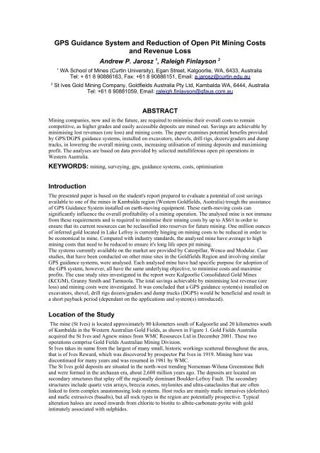
<strong>GPS</strong> <strong>Guidance</strong> <strong>System</strong> <strong>and</strong> <strong>Reduction</strong> <strong>of</strong> <strong>Open</strong> <strong>Pit</strong> <strong>Mining</strong> Costs<br />
<strong>and</strong> Revenue Loss<br />
Andrew P. Jarosz 1 , Raleigh Finlayson 2<br />
1 WA School <strong>of</strong> Mines (Curtin University), Egan Street, Kalgoorlie, WA, 6433, Australia<br />
Tel: + 61 8 90886163, Fax: +61 8 90886151, Email: a.jarosz@curtin.edu.au<br />
2 St Ives Gold <strong>Mining</strong> Company, Goldfields Australia Pty Ltd, Kambalda WA, 6444, Australia<br />
Tel: +61 8 90881059, Email: raleigh.finlayson@gfaus.com.au<br />
ABSTRACT<br />
<strong>Mining</strong> companies, now <strong>and</strong> in the future, are required to minimise their overall costs to remain<br />
competitive, as higher grades <strong>and</strong> easily accessible deposits are mined out. Savings are achievable by<br />
minimising lost revenues (ore loss) <strong>and</strong> mining costs. The paper examines potential benefits provided<br />
by <strong>GPS</strong>/D<strong>GPS</strong> guidance systems, installed on excavators, shovels, drill rigs, dozers/graders <strong>and</strong> dump<br />
tracks, in lowering the overall mining costs, increasing utilisation <strong>of</strong> mining deposits <strong>and</strong> maximising<br />
pr<strong>of</strong>it. The analyses are based on data provided by selected metalliferous open pit operations in<br />
Western Australia.<br />
KEYWORDS: mining, surveying, gps, guidance systems, costs, optimisation<br />
Introduction<br />
The presented paper is based on the student's report prepared to evaluate a potential <strong>of</strong> cost savings<br />
available to one <strong>of</strong> the mines in Kambalda region (Western Goldfields, Australia) trough the assistance<br />
<strong>of</strong> <strong>GPS</strong> <strong>Guidance</strong> <strong>System</strong> installed on earth-moving equipment. These earth-moving costs can<br />
significantly influence the overall pr<strong>of</strong>itability <strong>of</strong> a mining operation. The analysed mine is not immune<br />
from these requirements <strong>and</strong> is required to minimise their mining costs by up to A$6/t in order to<br />
ensure that its current resources can be reclassified into reserves for future mining. One million ounces<br />
<strong>of</strong> inferred gold located in Lake Lefroy is currently hinging on mining costs to be reduced in order to<br />
be economical to mine. Compared with industry st<strong>and</strong>ards, the analysed mine have average to high<br />
mining costs that need to be reduced to ensure it's long life open pit mining.<br />
The systems currently available on the market are provided by Caterpillar, Wenco <strong>and</strong> Modular. Case<br />
studies, that have been conducted on other mine sites in the Goldfields Region <strong>and</strong> involving similar<br />
<strong>GPS</strong> guidance systems, were analysed. Each analysed mine have had specific purpose for adoption <strong>of</strong><br />
the <strong>GPS</strong> system, however, all have the same underlying objective, to minimise costs <strong>and</strong> maximise<br />
pr<strong>of</strong>its. The case study sites investigated in the report were Kalgoorlie Consolidated Gold Mines<br />
(KCGM), Granny Smith <strong>and</strong> Tarmoola. The total savings achievable by minimising lost revenue (ore<br />
loss) <strong>and</strong> mining costs were investigated. It was concluded that a <strong>GPS</strong> guidance system(s) installed on<br />
excavators, shovel, drill rigs dozers/graders <strong>and</strong> dump trucks (D<strong>GPS</strong>) would be beneficial <strong>and</strong> result in<br />
a short payback period (dependant on the applications <strong>and</strong> system(s) introduced).<br />
Location <strong>of</strong> the Study<br />
The mine (St Ives) is located approximately 80 kilometers south <strong>of</strong> Kalgoorlie <strong>and</strong> 20 kilometres south<br />
<strong>of</strong> Kambalda in the Western Australian Gold Fields, as shown in Figure 1. Gold Fields Australia<br />
acquired the St Ives <strong>and</strong> Agnew mines from WMC Resources Ltd in December 2001. These two<br />
operations comprise Gold Fields Australian <strong>Mining</strong> Division.<br />
St Ives takes its name from the largest <strong>of</strong> many small, historic workings scattered throughout the area,<br />
that is <strong>of</strong> Ives Reward, which was discovered by prospector Pat Ives in 1919. <strong>Mining</strong> here was<br />
discontinued for many years <strong>and</strong> was resumed in 1981 by WMC.<br />
The St Ives gold deposits are situated in the north-west trending Norseman-Wiluna Greenstone Belt<br />
<strong>and</strong> were formed in the archaean era, about 2,600 million years ago. The deposits are located on<br />
secondary structures that splay <strong>of</strong>f the regionally dominant Boulder-Lefroy Fault. The secondary<br />
structures include quartz vein arrays, breccia zones, mylonites <strong>and</strong> ultra-cataclasites that are <strong>of</strong>ten<br />
linked to form complex anastomosing lode systems. Host rocks are mainly mafic intrusives (dolerites)<br />
<strong>and</strong> mafic extrusives (basalts), but all rock types in the region are potentially prospective. Typical<br />
alteration haloes are zoned inwards from chlorite to biotite to albite-carbonate-pyrite with gold<br />
intimately associated with sulphides.
Figure 1 Locations <strong>of</strong> St Ives <strong>and</strong> Agnew mines.<br />
<strong>GPS</strong> in <strong>Mining</strong><br />
The mining industry has been a leader in exp<strong>and</strong>ing usage <strong>of</strong> real-time <strong>GPS</strong>. <strong>Open</strong> pit mining <strong>of</strong>fers an<br />
ideal environment for application <strong>of</strong> <strong>GPS</strong>, combining open skies with pressing dem<strong>and</strong>s on increased<br />
productivity. Some <strong>of</strong> the reasons that <strong>GPS</strong> is so beneficial to the mining industry are:<br />
• Worldwide coverage<br />
• Services an unlimited number <strong>of</strong> users<br />
• Operates in all weather conditions<br />
• Accurate 3D positioning<br />
• Accurate timing<br />
• No line-<strong>of</strong>-sight restrictions<br />
• 24-hour availability<br />
• Dynamic positioning system<br />
• Free servicing<br />
<strong>GPS</strong> has numerous applications in the mining industry which can both assist increased productivity<br />
dem<strong>and</strong>s (increase revenue) <strong>and</strong> reduce mining cost <strong>and</strong> lost revenue.<br />
<strong>GPS</strong> applications in the mining industry include:<br />
• Vehicle tracking <strong>and</strong> dispatch.<br />
A radio link can relay the real-time position <strong>of</strong> a truck as determined by the <strong>GPS</strong> antenna mounted<br />
on the truck to the mine <strong>of</strong>fice. Computer s<strong>of</strong>tware at the <strong>of</strong>fice can determine <strong>and</strong> assign the most<br />
efficient route for each truck in the fleet.<br />
• Material tracking.<br />
The <strong>GPS</strong> system can determined what material each truck is carrying <strong>and</strong> where each load was<br />
dumped. If any discrepancies occur, the system informs the operator before the material is dumped<br />
at the incorrect location.<br />
• Bench height control.<br />
The grade <strong>of</strong> mined benches can be monitored in real-time without the need for manual survey, in<br />
both horizontal <strong>and</strong> vertical directions.<br />
• Ore control.<br />
The combined applications <strong>of</strong> <strong>GPS</strong> positioning <strong>and</strong> in-board display monitors enable the shovel<br />
operator to see what exactly is being mined.<br />
• Drill guidance.<br />
<strong>GPS</strong> guidance can be used to position the drill exactly over the design collar position <strong>and</strong> also drill<br />
to the exact design depth.<br />
• Shovel <strong>and</strong> loader operations.<br />
The combined applications <strong>of</strong> real-time <strong>GPS</strong> positioning <strong>and</strong> the mine map can assist in mining to<br />
design.<br />
• Haul Road grading <strong>and</strong> maintenance.<br />
Ensure roads are made <strong>and</strong> maintained to design.<br />
• Survey Stakeout.<br />
Survey crews can be reduced from the traditional two man crews to single man.<br />
• Topographic surveys for volumes.<br />
<strong>GPS</strong> data collected can be combined to assist in survey volume calculations.
• Earthmoving.<br />
<strong>Guidance</strong> to dozer operators increases dozer efficiency.<br />
• Elevation for rehabilitation work.<br />
Tolerances for rehabilitation work can be achieved with minimal cost.<br />
• Geological mapping.<br />
<strong>GPS</strong> can assist in creation <strong>of</strong> geological maps, whilst minimising costs,<br />
There are four basic levels <strong>of</strong> accuracy associated with <strong>GPS</strong>: Autonomous – 15 to 100 metres;<br />
Differential (D<strong>GPS</strong>) – 0.5 to 5 metres; Real Time Kinematic Float (RTK Float) – 20cm to 1 metre;<br />
Real Time Kinematic Fixed (RTK Fixed) – 1cm to 5cm.<br />
The most mining <strong>GPS</strong> systems are implemented as Differential <strong>GPS</strong> (D<strong>GPS</strong>) . These systems require a<br />
reference station that acts as a base for the entire <strong>GPS</strong> network at the mine site. The corrections<br />
calculated are from the <strong>GPS</strong> coordinates compared to the known coordinates <strong>of</strong> the references station<br />
<strong>and</strong> are transmitted by the radio network to the rovers in the field. When the rovers receive the<br />
corrections from the reference station, the corrections are applied to the position determined from the<br />
rovers <strong>GPS</strong>. In turn this enables the precise position to be known, all in real-time. One reference<br />
station can support unlimited rovers. To maintain communication between the reference station <strong>and</strong> the<br />
rovers a radio network is required at all times. If radio communication is required over long distances,<br />
radio repeaters can be installed around the site to relay the data corrections between the reference<br />
station to the rovers or onto another radio repeater in the network.<br />
Most radios used in <strong>GPS</strong> full in one <strong>of</strong> the following frequency ranges: 150 – 174 MHz (VHF); 406 –<br />
512 MHz (UHF) <strong>and</strong> 902 – 928 MHz (spread spectrum).<br />
The <strong>GPS</strong> guidance systems are applied to many aspects <strong>of</strong> mining operation including:<br />
Blasthole Drilling: <strong>GPS</strong> based blasthole drill systems available today provide drill monitoring, control<br />
<strong>and</strong> guidance. They consists <strong>of</strong> the following pieces <strong>of</strong> equipment: <strong>GPS</strong> receiver, <strong>GPS</strong> antenna, radio<br />
<strong>and</strong> radio antenna, cables, power supply, operator display, on-board computer, interfaces to third party<br />
s<strong>of</strong>tware, sensors to monitor drill <strong>and</strong> aid in material recognition.<br />
The prime objective <strong>of</strong> <strong>GPS</strong> positioning for drilling is to navigate the drill rig over the designed collar<br />
position. If achieved with the aid <strong>of</strong> <strong>GPS</strong> it eliminates the need for manual survey staking.<br />
In order to achieve navigation to drillholes, a design file needs to be loaded into the on-board<br />
computer. The drill rig is then navigated to each selected drillhole in sequence. The on-board display<br />
shows the position <strong>of</strong> the drill rig in relation to the drillhole as it trams into position.<br />
Once collared over the drillhole, the <strong>GPS</strong> determines the collar elevation <strong>and</strong> in conjunction with other<br />
technology, the correct depth <strong>of</strong> each hole is determined <strong>and</strong> continuously updated on the on-board<br />
display for the operator.<br />
Shovels, Loaders, Dozers <strong>and</strong> Graders: The process starts with the loading <strong>of</strong> the design file onto the<br />
machines on-board computer. The design file will traditionally be ore block designs, pit designs or<br />
road designs. The design information is overlaid with the machines current position, which provides<br />
the operator with all the assistance, required to mine the pit <strong>and</strong> ore block to design.<br />
As the machine progresses into the face the topography updates. The face position updates<br />
automatically from the <strong>GPS</strong> data coordinates received for the machine. The face position assists the<br />
operator <strong>and</strong> also the mine engineers in forecasting <strong>and</strong> scheduling decisions vital to running an<br />
efficient operation. The operator knows exactly when he/she is entering into a different ore block<br />
without totally relying on stakes or tape. The operator also knows when he/she is mining above or<br />
below the design floor grade; the on-board display highlights different colours on the display to denote<br />
if the machine is above, below or on grade.<br />
Vehicle Tracking <strong>and</strong> Dispatch: D<strong>GPS</strong> accuracy is required for position accuracy for the mines<br />
dump trucks. The D<strong>GPS</strong> positions obtained from the dump trucks are sent back to the central mine<br />
<strong>of</strong>fice were a computer determines <strong>and</strong> assigns its dumping location <strong>and</strong> then, where the trucks next<br />
loading destination will be. The system is interactive with all machines in the network. The <strong>GPS</strong><br />
system on the loading machines determines the material being mined from the design ore block file<br />
<strong>and</strong> it then determines what material each truck that has been loaded by that machine is carrying. This<br />
assignment is made automatically over the radio link <strong>and</strong> is displayed in the trucks cab. Once assigned,<br />
the system also tracks the trucks to ensure that the instructions are followed <strong>and</strong> no costly mistakes are<br />
made.
<strong>GPS</strong> Surveying: The <strong>GPS</strong> surveying rover pack is designed to be more lightweight <strong>and</strong> user friendly<br />
for survey personnel using the equipment on foot <strong>and</strong> walking over uneven ground. The basic pieces <strong>of</strong><br />
equipment required for <strong>GPS</strong> surveying are: <strong>GPS</strong> receiver, <strong>GPS</strong> antenna, radio <strong>and</strong> radio antenna,<br />
lightweight batteries for power, cables, backpack, h<strong>and</strong>held data collector.<br />
The distinct advantage <strong>of</strong> using <strong>GPS</strong> for surveying in open pit mining is that only a single surveyor is<br />
required to operate a <strong>GPS</strong> rover, compared to the traditional two-man crew when utilising a totalstation<br />
(theodolite) method <strong>of</strong> surveying.<br />
Future Developments: In the next future we will see the further refinement in size <strong>and</strong> flexibility <strong>of</strong><br />
<strong>GPS</strong> receivers. We will see smaller more advanced receivers combined with map display technology<br />
for lower cost as dem<strong>and</strong> <strong>and</strong> technology increase. Development is currently underway to integrate<br />
computer s<strong>of</strong>tware, therefore creating more uses for <strong>GPS</strong> information. The next generation in <strong>GPS</strong><br />
technology in mining will see additional sensors <strong>and</strong> sources <strong>of</strong> information applied <strong>and</strong> become<br />
interactive to provide users <strong>of</strong> the systems with the maximum information they will need to optimise<br />
their operations. The most exciting development on the horizon is an automated machine or truck<br />
guidance. These advances in technology will eventually significantly increase productivity <strong>and</strong><br />
increase safety the industry.<br />
<strong>GPS</strong> <strong>Guidance</strong> <strong>System</strong>s<br />
The following <strong>GPS</strong> <strong>Guidance</strong> <strong>System</strong> are available for installation on mining sites <strong>and</strong> were analysed<br />
in the referred study.<br />
Computer Aided Earthmoving <strong>System</strong> (CAES) by Caterpillar - Minestar<br />
The Computer Aided Earthmoving <strong>System</strong> (CAES) provides a real-time engineering plan that allows<br />
operators to instantaneously see how much material is required to be cut or filled without the use <strong>of</strong><br />
survey staking. This ensures that a re-h<strong>and</strong>le is greatly reduced. Material identification <strong>and</strong> pit floor<br />
design control is also achievable with the CAES system. The loading operator can see exactly what<br />
material is required to be mined in relation to the machine's current position; all in real-time. In turn all<br />
this information is relayed back to the <strong>of</strong>fice, reducing the number <strong>of</strong> mis-directed loads <strong>and</strong> allowing<br />
the mining engineers to accurately plan <strong>and</strong> forecast the shifts production.<br />
The CAES system provides managers, engineers <strong>and</strong> machine operators with significant benefits,<br />
including reducing survey time, less idle time <strong>and</strong> improved job quality. This results in a lower cost per<br />
ton for the movement <strong>of</strong> material.<br />
An important function <strong>of</strong> any mining operation is safety. CAES is especially valuable in areas that are<br />
hazardous <strong>and</strong> difficult to survey. Dangerous areas near large machinery are safer when workers are<br />
not on the ground. CAES minimises the need to manually place survey stakes in hazardous areas.<br />
CAES improves accuracy, saves time, lowers the cost per ton <strong>and</strong> helps safeguard the ground crew.<br />
The system replaces the manpower <strong>and</strong> time intensive processes associated with conventional<br />
surveying, allowing surveyor to spend more time performing other planning duties, including utilising<br />
CAES<strong>of</strong>fice. The data flow diagram <strong>of</strong> overall CAES <strong>System</strong> <strong>and</strong> interaction between its components<br />
is represented in Figure 2.<br />
Figure 2 Diagram <strong>of</strong> CAES <strong>System</strong>.
The components that make up the dozer installed system are shown in Figure 3. These include antenna,<br />
display console, receiver <strong>and</strong> radio are shown. The data flow traverse is illustrated in Figure 4. Figures<br />
5 <strong>and</strong> 6 are examples <strong>of</strong> the CAES<strong>of</strong>fice <strong>and</strong> METSmanager screens available to mine management in<br />
their <strong>of</strong>fices.<br />
Figure 3 Components <strong>of</strong> CASE<br />
installed at dozer or drill-rig.<br />
Figure 5 CAES<strong>of</strong>fice screen.<br />
Aquila Drill Management<br />
Figure 4 Diagram <strong>of</strong> data flow via radio.<br />
Figure 6 METSmanager screen.<br />
The drill management component <strong>of</strong> the Minestar system is supplied by Aquila <strong>Mining</strong> <strong>System</strong>s.<br />
Aquila is a pioneer in the development <strong>of</strong> advanced, computer-based monitoring, control <strong>and</strong> guidance<br />
systems for drilling activities in the mining industry. Aquila <strong>of</strong>fers a rugged product specifically<br />
designed to survive in hash mining environments to maximise equipment productivity. Effective <strong>and</strong><br />
efficient mine management <strong>and</strong> planning is enhanced with the Aquila drill management system, whilst<br />
reducing costs. Aquila systems can make drilling <strong>and</strong> blasting operations more accurate, productive<br />
<strong>and</strong> pr<strong>of</strong>itable with the utilisation <strong>of</strong> <strong>GPS</strong> technology in conjunction with advanced computer-based<br />
technology. The system provides the drilling operator with real time centimeter accuracy positioning to<br />
ensure that the blast holes are drilled exactly on design to maximise fragmentation <strong>and</strong> production<br />
whist reducing blasting costs.<br />
The system <strong>of</strong>fered by Caterpillar – Minestar is extensive <strong>and</strong> includes significant number <strong>of</strong><br />
components that support different aspects <strong>of</strong> mining operation.<br />
The list <strong>of</strong> additional components includes:<br />
• The Minestar Production system that allows real-time production information to be obtainable<br />
during the shift for improved management control. A Minestar Office Database automatically logs<br />
all machine actions, which in turn allows the computation <strong>of</strong> material movement. Web-based<br />
reporting tools allow personnel to quickly produce reports than can be delivered anywhere in the<br />
world in seconds.<br />
• The Minestar Fleetcomm<strong>and</strong>er . The system is designed to ensure mine-planning requirements<br />
are met, shovel utilisation is maximised <strong>and</strong> truck wait time is minimised all specifically aimed at<br />
lowering costs.<br />
• The Minestar Machine Tracking system enables mine management to see exactly what each
machine within the fleet is loading <strong>and</strong> hauling. It is aimed at evaluating <strong>and</strong> analysing dump<br />
movement, haul road congestion <strong>and</strong> speed restrictions.<br />
• The Minestar Material Tracking system is based on communication between the loading tool <strong>and</strong><br />
truck. The material the truck is hauling can be assigned a destination based on grade <strong>and</strong> balancing<br />
<strong>of</strong> stockpile volumes. Once assigned, the truck can be tracked to its destination to ensure misrouted<br />
truck loads are detected. All information is collected in real-time; therefore this system acts as a<br />
preventative tool.<br />
• The Minestar Health system is based on a Vital Information Management <strong>System</strong> (VIMS) which<br />
collects machine health information <strong>and</strong> transmits the vital information to the workshop for remote<br />
diagnostics. It allows to see what, where <strong>and</strong> when a problem is occurring from the maintenance<br />
facility.<br />
• The Minestar Business Enterprise system has the ability to be linked to the Enterprise<br />
Information <strong>System</strong>. This enables mine accounting, mine planning, asset management <strong>and</strong> human<br />
resource systems to be linked to the machines in the field.<br />
WENCO <strong>System</strong><br />
The Wenco system brings together <strong>GPS</strong>, radio communication, computer technology <strong>and</strong> s<strong>of</strong>tware<br />
applications to track <strong>and</strong> improve the activity <strong>and</strong> performance <strong>of</strong> equipment in surface mines. It uses<br />
Windows CE OS for mobile computing applications. Oracle is used for data organisation <strong>and</strong> Crystal<br />
Reports is used to access the information. Wenco has become the worlds leading suppler <strong>of</strong><br />
PC/Windows based Mine Management <strong>System</strong>s.<br />
Wenco <strong>of</strong>fers a wide range <strong>of</strong> applications that build together a state-<strong>of</strong>-the-art computerised mine<br />
management system. The list <strong>of</strong> applications includes: high precision <strong>GPS</strong>, fleet management,<br />
dispatching, ore quality control, stockpile management, MineVision, bench elevation <strong>and</strong> bucket<br />
positioning, dozer guidance, drill navigation <strong>and</strong> sensor monitoring, TireMax, payload management,<br />
condition monitoring, alarm management, maintenance management, auto cycling, WencoDB, Wenco<br />
Inquires, reporting <strong>and</strong> SAMS – <strong>System</strong> Availability Measurement S<strong>of</strong>tware. The overall capabilities<br />
<strong>of</strong> WENCO <strong>System</strong> are comparable to system <strong>of</strong>fered by Caterpillar – Minestar.<br />
MODULAR <strong>System</strong><br />
Modular <strong>Mining</strong> <strong>System</strong> Inc., founded in 1979, is part <strong>of</strong> the Komatsu family <strong>of</strong> companies. Modular<br />
<strong>Mining</strong> <strong>System</strong>s <strong>of</strong>fers a full line <strong>of</strong> products <strong>and</strong> s<strong>of</strong>tware to meet the needs <strong>of</strong> both open pit <strong>and</strong><br />
underground operation management. Modular’s INTELLIMINE system not only <strong>of</strong>fers a DISPATCH<br />
system, but also incorporates truck assignments, <strong>GPS</strong>-based equipment positioning, equipment health<br />
monitoring, maintenance tracking, blending, Web based production reporting, <strong>and</strong> more.<br />
Modular <strong>Mining</strong> products are designed to maximise the productivity <strong>of</strong> mining operations by tightly<br />
integrating all phases <strong>of</strong> production. This is achieved by utilising state <strong>of</strong> the art information, <strong>GPS</strong> <strong>and</strong><br />
communication technology. Modular mining allows clients to achieve increases in productivity,<br />
averaging more than 10 percent. The system improves operational efficiency by providing integrated<br />
technologies that optimise the performance <strong>of</strong> the open pit mine assets.<br />
The ProVision Shovel system is a fully integrated INTELLIMINE subsystem designed to improve<br />
ore control <strong>and</strong> bench elevation. Analysis <strong>of</strong> the shovel bucket position is achieved with high precision<br />
<strong>GPS</strong>. Swinging, digging <strong>and</strong> dumping actions are determined, which enables the system to highlight<br />
the polygon the shovel is currently mining <strong>and</strong> assign the exact dig points for each polygon mined<br />
during the shift.<br />
For ore control, the system uses high precision <strong>GPS</strong>, along with design parameters from mine-planning<br />
packages, a wireless radio network <strong>and</strong> onboard Colour Graphics Consoles (CGC). The CGC shows<br />
the operator precisely where to dig, including a map <strong>of</strong> the material polygons at the bench face, the<br />
polygon the operator is currently digging (highlighted), the dig points in the polygon <strong>and</strong> the real time<br />
dig line (face position).<br />
The system allows the operators to verify that they are digging <strong>and</strong> classifying the correct material,<br />
even at night <strong>and</strong> during inclement weather. It also translates to less dilution <strong>of</strong> material at polygon<br />
boundaries for more accurate load accounting <strong>and</strong> blending.
For bench elevation control, CGC uses a height gauge that informs the operator <strong>of</strong> the current floor<br />
level. This is used against the design elevation to determine cut <strong>and</strong> fill values. This virtually<br />
eliminates undercutting <strong>and</strong>/or overcutting, that usually result in costly reworking. The height gauge is<br />
also invaluable for mining ramps, inclined floors for drainage purposes <strong>and</strong> maintaining a flat pit floor.<br />
Hazards <strong>and</strong> miscellaneous features can be displayed on the CGC, including underground workings,<br />
misfires <strong>and</strong> no dig lines. This provides valuable safety <strong>and</strong> production information, whilst reducing<br />
reworking <strong>and</strong> costs. Data related to dig locations, bucket counts <strong>and</strong> material type is continually<br />
recorded as the shovel operates. This information is then available in the systems comprehensive<br />
reporting facility that provides a wealth <strong>of</strong> information for analysis <strong>of</strong> the shovel operation. These data<br />
can be transferred to a mine-planning package to determine the dig advance <strong>and</strong> update the mine<br />
model. The mine design material, including ore boundaries, pit designs <strong>and</strong> elevation designs are<br />
loaded in the INTELLIMINE central computer, which is then accessible by the mobile mining fleet<br />
via the wireless radio network. Any changes that occur in the mine design package are automatically<br />
updated to ensure mining is conducted to design.<br />
The High Precision Drill positioning system uses high precision <strong>GPS</strong> in conjunction with an onboard<br />
Graphics Console (GC) to display the design drill pattern, using predefined blast hole coordinates in<br />
the system database. Utilising this information, the drill operators zoom in on the hole locations <strong>and</strong><br />
begin drilling without the use <strong>of</strong> site markers. Once positioned, the drill operator can change the GC<br />
display to show drill depths, penetration rates <strong>and</strong> depths to the bottom <strong>of</strong> the hole. This system<br />
provides a significant cost saving by reducing costly under- <strong>and</strong> over-drilling.<br />
The High Precision Dozer system is designed to improve the productivity <strong>of</strong> both track <strong>and</strong> wheel<br />
dozers in surface mines. Information displayed to the dozer operator includes a map <strong>of</strong> the work<br />
region, the dozers real-time position, continuously updated cut <strong>and</strong> fill requirements <strong>and</strong> the position <strong>of</strong><br />
local hazards. The high precision <strong>GPS</strong> system provides centimetre accuracy, day <strong>and</strong> night without the<br />
requirement <strong>of</strong> flags, stakes or other survey requirements. It also eliminates costly rework due to<br />
insufficient survey demarcation.<br />
The MODULAR includes also: Vehicle Health <strong>System</strong> (VHS) <strong>and</strong> Executive Reporting <strong>System</strong>.<br />
Modular <strong>Mining</strong> <strong>System</strong>s <strong>and</strong> its partners are developing the Autonomous Haulage <strong>System</strong>, which will<br />
eventually allow mines to operate unmanned haul trucks. Once the system has been developed <strong>and</strong><br />
commissioned it will signal the beginning <strong>of</strong> a new era in mining history for the top performing<br />
operations seeking further technological advancement <strong>and</strong> continuous improvement.<br />
Case Studies <strong>of</strong> <strong>GPS</strong> <strong>Guidance</strong> <strong>System</strong>s<br />
Case Study 1: Kalgoorlie Consolidated Gold Mines (KCGM)<br />
Kalgoorlie Consolidated Gold Mines (KCGM) is the joint venture operation between Newmont (50%)<br />
<strong>and</strong> Barrick (50%). The gold mining operation is located on the perimeter <strong>of</strong> Kalgoorlie/Boulder,<br />
Western Australia. The Fimiston <strong>Open</strong> <strong>Pit</strong> (commonly referred to as the Super <strong>Pit</strong>) is the largest open<br />
pit gold mine in Australia. When completed it will be approximately 4 kilometres long, 1.5 kilometres<br />
wide <strong>and</strong> 650 metres deep. It is anticipated that the mine will produce more than 10 million ounces <strong>of</strong><br />
gold over its expected life <strong>of</strong> 16 years. Currently the open pit operation moves around 85 million<br />
tonnes <strong>of</strong> material per year making it the single largest open pit operation <strong>of</strong> any commodity in<br />
Australia, on a tonnes per annum basis. Of this some 12 million tonnes <strong>of</strong> gold bearing ore are<br />
produced <strong>and</strong> milled through the Fimiston Mill. The remaining material is comprised <strong>of</strong> lower grade<br />
ore <strong>and</strong> waste. The strip ratio for the operation is between 5.5 <strong>and</strong> 6.<br />
KCGM is the largest gold mine in Australia, accounting for approximately 10% <strong>of</strong> Australia’s gold<br />
production. The operation produces up to 850,000 ounces <strong>of</strong> gold per year.<br />
The ore is found in steeply dipping, narrow lode systems with an average grade <strong>of</strong> 2.5 g/t. The open pit<br />
is mining through historical underground workings, that pose significant mining <strong>and</strong> safety issues.<br />
The operation decided to cease contractor mining in late 1999 <strong>and</strong> opted for an “owner miner”<br />
operation primarily to reduce costs. There were also several other reasons the operation decided to go<br />
“owner miner” including:<br />
• Continuous improvements in all facets <strong>of</strong> the operation, like mining planning, grade control,<br />
scheduling <strong>and</strong> mining equipment maintenance <strong>and</strong> utilisation,<br />
• Improved safety <strong>and</strong> environmental performance,
• Higher truck <strong>and</strong> shovel productivity,<br />
• Reduced duplication <strong>of</strong> management, <strong>and</strong><br />
• Lower mining <strong>and</strong> supervisory costs.<br />
KCGM maintains close attention to geology, geotechnical planning, scheduling <strong>of</strong> earthmoving<br />
equipment, drill <strong>and</strong> blast technology <strong>and</strong> safety to maintain control <strong>of</strong> costs <strong>and</strong> efficiencies.<br />
<strong>Mining</strong> is conducted using hydraulic shovels with bucket capacities <strong>of</strong> 35 cubic metres <strong>of</strong> broken<br />
material loaded into 220 tonne capacity haul trucks (Figure 7). The mining material is classified <strong>and</strong><br />
then delineated by grade <strong>and</strong> transported to their correct destinations as detailed below:<br />
• High grade (>1.2g/t) to the mill,<br />
• Medium grade (0.9 to 1.2g/t) to the medium grade stockpile,<br />
• “Sub-grade” (0.5 to 0.9 g/t) to the sub-grade stockpile,<br />
• Waste (
The CAES system can also be utilised for mining to a specific design grade. <strong>Pit</strong> floors <strong>and</strong> ramps<br />
mined to design grade are vital for minimising costly re-mining <strong>and</strong>/or ore loss. Good surface haulage<br />
conditions are vital for maximising tyre life. Dump truck tyres cost approximately $26,000 each;<br />
therefore maximising tyre life is essential. Dozers use CAES for grade control. This includes<br />
roadworks; ramps, rip lines, stockpiles <strong>and</strong> waste dump rehabilitation. All waste dump work (with the<br />
exception <strong>of</strong> final limits <strong>and</strong> environmentally sensitive areas) is performed stake free <strong>and</strong> is controlled<br />
entirely by CAES <strong>and</strong> mine design s<strong>of</strong>tware, enhancing safety <strong>and</strong> economic benefits. The major<br />
benefit <strong>of</strong> the CAES system to KCGM has been associated with enhanced safety in relation to working<br />
<strong>and</strong> operating around underground voids.<br />
CAES<strong>of</strong>fice, the <strong>of</strong>fice-based s<strong>of</strong>tware allows KCGM site designers to see results instantly while<br />
tracking progress accurately without having to leave the <strong>of</strong>fice, therefore improving planning <strong>and</strong><br />
forecasting.<br />
Geologists use CAES<strong>of</strong>fice to mark ore boundaries as accurately as possible. <strong>System</strong> helps to predict<br />
when geologist should go down to shovel to spot ore contact <strong>and</strong> give shovel operators clearer<br />
instructions on how to approach a contact, as well as, steer them away from areas by designing ‘No<br />
Dig’ lines in the display data. Geologists are also responsible for creating <strong>and</strong> uploading the correct<br />
material files to the shovels.<br />
Drill <strong>and</strong> Blast Engineers use CAES<strong>of</strong>fice to gain spotheight data from CAES to create DTM’s for<br />
designing blasthole depths. The drill <strong>and</strong> blast department also create display data files <strong>of</strong> all charged<br />
shots in the pit using Surpac.<br />
Mine Planning Engineers use CAES<strong>of</strong>fice for the Development <strong>of</strong> dumps in line with long-term<br />
strategy <strong>and</strong> monthly schedules by designing perimeters within which the dozer operators can work,<br />
hence controlling the dump development. This is redesigned each month <strong>and</strong> uploaded to the dozers by<br />
the engineers. Likewise, the mine planning engineers maintain a single file containing all current in-pit<br />
ramps. <strong>Pit</strong> <strong>and</strong> dump progress is also checked in CAES to assist in the development <strong>of</strong> schedules <strong>and</strong><br />
plans.<br />
Production Engineers <strong>and</strong> Foremen use CAES<strong>of</strong>fice as a type <strong>of</strong> GIS to assist with sharing <strong>of</strong><br />
information at shift change <strong>and</strong> to plan digging <strong>and</strong> access in hazardous areas. CAES lets foremen<br />
design <strong>and</strong> construct temporary ramps without engineering or survey intervention.<br />
Bucket positions are estimated by the CAES system on shovels based on the reach <strong>of</strong> the bucket. Crest<br />
positions are determined by CAES from the angle <strong>of</strong> repose <strong>of</strong> blasted rill material <strong>and</strong> bench heights.<br />
KCGM has found accuracy <strong>of</strong> the bucket positioning to be <strong>of</strong> +/- 2m.<br />
Overall the CAES <strong>GPS</strong> guidance system has been successful at KCGM since its implementation in<br />
September 1999; it has proven to be robust <strong>and</strong> entirely suitable for mining applications.<br />
WENCO <strong>System</strong>. Before implementation <strong>of</strong> CAES, the mining contractor (Roche <strong>Mining</strong>) opted for<br />
the ‘Wenco’ dispatch system primarily for costs benefit reasons. The system has proved to be<br />
successful since its implementation <strong>and</strong> is still utilised by KCGM today. Currently the Wenco dispatch<br />
system is installed on all 20 (Cat 793) dump trucks, all 4 Komatsu shovels <strong>and</strong> all the contractor<br />
auxiliary equipment.<br />
Case Study 2: Granny Smith<br />
The Granny Smith mine is owned through a joint venture between Placer Dome Asia Pacific Ltd (60%<br />
) <strong>and</strong> Aurion Gold Ltd. (formerly Delta Gold Limited) (40%). Placer (Granny Smith) Pty Ltd is the<br />
manager <strong>and</strong> is a wholly owned subsidiary <strong>of</strong> Placer Dome Asia Pacific Ltd. Production is subject to a<br />
2.5% GSR royalty, payable to the State. Granny Smith open pit gold mine started production in<br />
February 1990. Located near Laverton, in Western Australia, the mine currently employs<br />
approximately 450 people, including 190 contractors. The original Granny Smith deposit, which<br />
consisted <strong>of</strong> three discontinuous zones (Granny, Goanna <strong>and</strong> Windich), was mined out in 1995. Five<br />
satellite deposits have also been depleted. Ore is currently supplied from the Wallaby deposit.<br />
Development <strong>of</strong> the Wallaby deposit began in October 2000 <strong>and</strong> ore production commenced in<br />
October 2001. The proven <strong>and</strong> probable mineral reserves at December 31, 2001 contained 2.5 million<br />
ounces <strong>of</strong> gold (0.2 million ounces proven <strong>and</strong> 2.3 million ounces probable). Granny Smith has a<br />
projected mine life <strong>of</strong> 9 years. During 2001, the mine produced 347,177 ounces <strong>of</strong> gold. Placer Dome's<br />
share <strong>of</strong> production was 208,306 ounces at an average cash <strong>and</strong> total cost <strong>of</strong> $167 <strong>and</strong> $181 per ounce,<br />
respectively.
Granny Smith currently has Caterpillar’s CAES system installed on two shovels <strong>and</strong> one D10 Dozer,<br />
with the intention <strong>of</strong> installing another system on a 992 Loader. Initially the mine had the CAES<br />
system installed on two excavators <strong>and</strong> at one stage had the system running in two pits concurrently.<br />
Two drill <strong>and</strong> blast drill rigs had the Aquila drill management systems installed in March 2001.<br />
Improved fragmentation was the main reason for the new systems on the drills. The net effect <strong>of</strong><br />
improved fragmentation was increased productivity for the mining fleet. Orica, the explosives provider<br />
for all drill <strong>and</strong> blast requirements at Wallaby have a Bulk Master <strong>GPS</strong> system on all explosive trucks<br />
so that the precise amount <strong>of</strong> explosive are distributed over the entire shot as pre-determined from the<br />
material recognition function <strong>of</strong> the Drill Management system. Drilling operations in Wallaby pit are<br />
shown in Figure 8.<br />
Figure 8 Drilling in Wallaby pit.<br />
CAES was trialed at Sunrise pit from April 1, 2000 to June 30, 2000. The purpose <strong>of</strong> the trial was to<br />
establish the performance <strong>of</strong> CAES against predefined performance targets, <strong>and</strong> to assist with the<br />
justification to purchase the system. To determine the benefits <strong>of</strong> the system, the mining units were<br />
tested with <strong>and</strong> without CAES (full trial <strong>and</strong> blind trial). The blind trials incorporated fully functional<br />
CAES, with the operators screen blacked out so that the CAES advantages are not available to the<br />
operator. To measure performance against the specified targets, two main trials were performed. The<br />
CAES excavator trial consisted <strong>of</strong> manual shift productivity reports against CAES data. The CAES<br />
data was filtered for inconsistencies. A total <strong>of</strong> 171,000 <strong>GPS</strong> positions were considered. The analysis<br />
<strong>of</strong> the data was performed by matching the truckload times with the CAES times <strong>and</strong> comparing the<br />
load types to check for inconsistencies. All misclassified buckets were closely analysed, to ensure the<br />
data was valid. Since most misclassifications were found at the boundary <strong>of</strong> ore blocks, a tolerance <strong>of</strong><br />
1.5m was allowed around ore boundaries. This tolerance was chosen, as it is roughly half the width <strong>of</strong><br />
the EX3500’s bucket <strong>and</strong> is consistent with inaccuracies introduced with the current methods <strong>of</strong> ore<br />
mark-up (survey tolerance, painting tolerances, <strong>and</strong> rilling <strong>of</strong> ore faces). Buckets that fell outside the<br />
tolerance were used in dilution calculations. The trial conducted on the excavator showed a significant<br />
reduction in ore sent to the waste dump (0.963% <strong>of</strong> waste was actually ore misdirected when operating<br />
without CAES, <strong>and</strong> 0.366% with CAES). This satisfied the first performance target (reduction <strong>of</strong> 50%<br />
in ore mined as waste). In addition, it was realised that a higher proportion <strong>of</strong> waste was being sent to<br />
the ore stockpiles, a proportion which was similarly reduced with the introduction <strong>of</strong> CAES (9.18% <strong>of</strong><br />
ore sent to stockpiles was actually waste when operating without CAES, compared to 4.46% with<br />
CAES). Improved operator familiarity with the system could yield even better results.<br />
The results <strong>of</strong> the two trials showed that dilution was effectively halved using the CAES system. This<br />
improvement, when applied to the full period <strong>of</strong> the trial (3 months) equates to a direct saving <strong>of</strong><br />
$627,830 ($209,276/month). A payback period <strong>of</strong> 0.2 years was determined from the initial costs <strong>and</strong><br />
the direct savings achieved. Based on this result alone, the system easily met the criteria required to<br />
justify the expenditure.<br />
The Granny Smith operators have been very positive towards the system, realising the potential<br />
benefits <strong>and</strong> recognising it as an effective tool to help them provide a better quality product. Following<br />
the success <strong>of</strong> the initial installations, the Granny Smith engineers have recommended to their
management, the immediate purchase <strong>of</strong> an additional system to complement their CAES fleet. The<br />
approximate cost per operational piece <strong>of</strong> loading equipment with a CAES system installed is<br />
US$75,000. Additional costs are incurred with base stations <strong>and</strong> repeaters. However considering the<br />
‘pay back’ period is only 0.2 years; the initial costs seem insignificant compared to the systems full<br />
potential cost savings.<br />
Case Study 3: Tarmoola<br />
Tarmoola is located approximately 29 kilometres North/East <strong>of</strong> Leonora <strong>and</strong> forms part <strong>of</strong> the<br />
North/Eastern Goldfields gold district, which includes Sons <strong>of</strong> Gwalia’s Leonora operation. Mount<br />
Edon Gold Mines brought the Tarmoola gold mine into production in May 1990. Camelot Resources<br />
<strong>and</strong> Teck Corporation acquired Edon in March 1998. This consolidated ownership was renamed <strong>and</strong><br />
became PacMin <strong>Mining</strong> Corporation. Sons <strong>of</strong> Gwalia completed a takeover <strong>of</strong> Tarmoola in October<br />
2001. In the 11 years until 30 June 2001, the Tarmoola mine produced a total <strong>of</strong> 1.1 million ounces <strong>of</strong><br />
gold. The Tarmoola mine is a large scale open pit operation extracting in excess <strong>of</strong> 30 million tonnes<br />
<strong>of</strong> material per annum. The processing plant treats some 3.5 million tonnes <strong>of</strong> gold bearing ore each<br />
year.<br />
Currently Tarmoola utilises the Wenco dispatch module. The system was acquired for accurate<br />
reporting <strong>of</strong> mining production. The system uses “weightometers” on the trucks to determine payload<br />
information, which is relayed to the mining <strong>of</strong>fice for analysis via a wireless network. The Wenco<br />
system also provides critical information to the maintenance department, which enables them to service<br />
<strong>and</strong> maintain the mining fleet with efficiency <strong>and</strong> without delaying production. This system also<br />
enables tracking <strong>and</strong> recording <strong>of</strong> causes <strong>of</strong> equipment failures <strong>and</strong> mechanical deficiencies. The third<br />
major reason for adoption <strong>of</strong> a dispatch module was material tracking purpose. This system was the<br />
most financially beneficial component <strong>of</strong> the entire system. It uses D<strong>GPS</strong> mounted in the trucks to<br />
locate their dumping destinations. The system uses beacons along the haul roads to ensure that the<br />
truck is travelling to the correct dumping location relevant to the material it is carrying. An alarm<br />
notification system is in place on the mine site, which notifies the truck operator <strong>and</strong> the mining <strong>of</strong>fice<br />
that a misallocated dump may occur; therefore enabling the truck to re-route <strong>and</strong> dump its load at the<br />
correct destination.<br />
The benefit <strong>of</strong> the system is that it allows the company to track <strong>and</strong> correct the losses detailed above,<br />
which previously were suspected but not quantified. This further enables the company to justify the<br />
implementation <strong>of</strong> the system with cost analysis calculations related to payback periods <strong>and</strong> future<br />
financial benefits <strong>of</strong> the system.<br />
Analysis <strong>of</strong> Benefits <strong>and</strong> Cost Savings for St Ives Mine<br />
The comprehensive compilation <strong>of</strong> all the benefits <strong>and</strong> cost savings as determined from the<br />
investigations, conducted at the case study mines, is presented in this section. The benefits <strong>and</strong> cost<br />
savings are specifically related to St Ives open pits. All direct <strong>and</strong> indirect benefits <strong>of</strong> the installation <strong>of</strong><br />
a <strong>GPS</strong> guidance system installed at St Ives open pits have been considered <strong>and</strong> investigated.. Cost<br />
saving analysis is performed for all applications, which may result in a direct cost saving to St Ives.<br />
The benefits <strong>and</strong> cost savings are evaluated by application <strong>and</strong> cost saving potential, therefore enabling<br />
St Ives management to gauge the potential benefits <strong>and</strong> cost savings for each application. At the<br />
conclusion <strong>of</strong> this section, a weighted average analysis is conducted to provide St Ives management<br />
with the potential cost savings that would be achievable with the installation <strong>of</strong> a <strong>GPS</strong> guidance<br />
system.<br />
The Table 1 shows all the potential benefits <strong>and</strong> cost savings achievable for each <strong>of</strong> the <strong>GPS</strong> guidance<br />
systems classified by machine type. The applications designated with an (*) are deemed to be those<br />
that provide the most substantial costs savings <strong>and</strong>/or benefits.<br />
The potential cost savings achievable for all the <strong>GPS</strong> guidance applications available by machine type<br />
are compiled in Table 2. The monthly <strong>and</strong> annual savings are determined based on the cost analysis .<br />
Conservative percentages have been applied on top <strong>of</strong> the conservatism already applied to the cost<br />
savings figures. This approach was applied to analysis to guarantee the return on investment. As<br />
shown in Table 2, the projected potential annual savings are <strong>of</strong> A$3,681,390. This equates to<br />
approximately A$1,533,912 for current pit reserves (until May 2003). The conservative approach to<br />
analysis should provide management with secure, yet realistic cost saving per annum.
Potential Benefits <strong>and</strong> cost savings with <strong>GPS</strong> guidance systems<br />
<strong>GPS</strong> guidance on…<br />
Benefits <strong>and</strong> Cost Savings Excavators/Shovel Dozers Graders Trucks (Dispatch) Drill & Blast<br />
Reduce misidentified loads * X<br />
Correct floor elevation * X X X<br />
Increased Productivity * X X X X X<br />
Reduce idle time X X X X<br />
Improved mine planning X X X<br />
Mine to design X X X<br />
<strong>Mining</strong> subgrade blocks X<br />
No dig lines X X<br />
Edge <strong>of</strong> blast information X X<br />
Reduced survey requirements X X X<br />
24/7 survey assistance * X X X X X<br />
Working around voids * X X<br />
Reduce floor dilution & ore loss * X X<br />
Establish dropcut on grade X X X<br />
Flatten heave X<br />
Waste removal on ore zones X X X<br />
Waste dump construction X<br />
Backfilling pits X<br />
Material tracking * X X<br />
Accurate overhaul cost X<br />
Tonnage/truck determination X X<br />
Reduce idle time X X X X<br />
Improved fragmentation * X<br />
Reduced labor cost X X X X<br />
Table 1 Overall potential cost savings <strong>and</strong> benefits by machine type.<br />
<strong>GPS</strong> Cost saving<br />
Potential Cost Savings (A$)<br />
Monthly Annual Conservative Adjusted<br />
Machine Application Savings Savings (%) Annual savings<br />
Misidentified loads $297,123 $3,565,476 50% $1,782,738<br />
Excavators Mine to correct floor elevation $93,150 $1,117,800 50% $558,900<br />
Shovel Increased Productivity $19,000 $228,000 25% $57,000<br />
<strong>Mining</strong> to design $4,138 $49,650 50% $24,825<br />
Doze to design floor elevation $19,244 $230,929 50% $115,465<br />
Dozer Doze/Grade within ore boundaries $10,491 $125,892 25% $31,473.00<br />
Material Tracking $90,772 $1,089,264 50% $544,632<br />
Trucks Accurate overhaul costs $45,221 $542,652 75% $406,989<br />
Improved fragmentation $17,603 $211,236 50% $105,618<br />
Drill & Blast Minimal survey requirements $11,250 $135,000 25% $33,750<br />
Minimal dipping requirements $6,667 $80,000 25% $20,000<br />
TOTAL $614,658 $7,375,899 43% $3,681,390<br />
Table 2 Potential cost savings for all <strong>GPS</strong> guidance system applications.
The estimation <strong>of</strong> costs <strong>of</strong> <strong>GPS</strong> guidance system for the various mining machines was based on<br />
purchase prices <strong>of</strong> similar systems when acquired by other mine sites. Costs would be significantly<br />
cheaper if an entire mining fleet was purchased with <strong>GPS</strong> guidance system installed. Based on the full<br />
purchase prices for an entire mining, drilling <strong>and</strong> blasting fleet the estimated total costs is<br />
approximately A$1,194,115. This includes system for four (4) mining machines, ten (10) trucks<br />
(Dispatch), two (2) radio repeaters <strong>and</strong> four (4) production drill rigs. This entire purchase price is less<br />
than the return on investment calculated for the current mining pit reserves (4-5 months production).<br />
Therefore the payback period determined for the system is 3.8 months, with all conservatism included.<br />
Conclusions<br />
The analysis <strong>of</strong> <strong>GPS</strong> <strong>Guidance</strong> <strong>System</strong> case studies suggest that such systems may have significant<br />
impact on management <strong>of</strong> earth-moving equipment <strong>and</strong> at accuracy <strong>of</strong> mining operations. The pay<br />
back period may vary depending on the time <strong>and</strong> resources put into the system to realise it's full<br />
potential either directly or indirectly. The ideal environment for the installation <strong>of</strong> a <strong>GPS</strong> guidance<br />
system would be in a mine with a long life (>1 year). This way the payback <strong>of</strong> the system would be<br />
ensured <strong>and</strong> the benefits <strong>and</strong> cost savings could be realised for longer.<br />
The analysed case study suggests that the mine would benefit from the installation <strong>of</strong> a <strong>GPS</strong> guidance<br />
system. The payback period is estimated to be only 3.8 months based on an approximate initial<br />
invested capital <strong>of</strong> A$1,200,000 for a full <strong>GPS</strong> guidance <strong>and</strong> dispatch system. The report determines<br />
that the potential cost savings at average size open pit mine with a <strong>GPS</strong> guidance system installed is in<br />
the order <strong>of</strong> A$300,000/month. For the St Ives mine, based on the current reserves remaining for all<br />
pits <strong>and</strong> assuming average production rates, the potential cost savings are A$1,533,912 . All future<br />
reserves would also enjoy the benefits <strong>and</strong> cost savings achievable with a <strong>GPS</strong> guidance system.<br />
Acknowledgements<br />
Authors would like to acknowledge the assistance <strong>and</strong> help from the following individuals, sources<br />
<strong>and</strong> companies when preparing this report: pr<strong>of</strong>essionals at St Ives Gold Mine , Kalgoorlie<br />
Consolidated Gold Mines (KCGM), Granny Smith Gold Mine, Caterpillar, Wenco <strong>and</strong> Modular.<br />
References<br />
Trimble Navigation Limited. 1997, <strong>GPS</strong> for mining, United States.<br />
Wenco International <strong>Mining</strong> <strong>System</strong>s. 2003, http://www.wencomine.com, News, Vancouver, Canada.<br />
Wenco International <strong>Mining</strong> <strong>System</strong>s. 2003, http://www.wencomine.com/products. asp, Product<br />
Overview, Vancouver, Canada.<br />
Caterpillar. 2003, http://www.cat.com/products/shared/technology_products/01_products, Technology<br />
Products, United States.<br />
Caterpillar. 2003, http://www.cat.com/products/shared/technology_products/future developments,<br />
Future Developments, United States.<br />
Caterpillar. 2003, http://ww.cat.com/products/shared/technology_products/02_product_information,<br />
Product Information, United States.<br />
Modular <strong>Mining</strong> <strong>System</strong>s. 2003, whttp://www.mmsi.com/modular/news, Company News, Arizona,<br />
USA.<br />
Greene, D. 2001. Value <strong>of</strong> <strong>GPS</strong> <strong>and</strong> Computer Aided Earthmoving <strong>System</strong>s in L<strong>and</strong>fills, SWANA<br />
L<strong>and</strong>fill Symposium 2001. (668K PDF, available from http://www.cat.com/products/shared/<br />
technology_products/pdf/swana_l<strong>and</strong>fill_symposium2001.pdf )<br />
Greene, D. <strong>and</strong> Buhl, B. 2000. Transitioning Surface Gold <strong>Mining</strong> into the 21st Century,Transitioning<br />
Surface Gold <strong>Mining</strong> into the 21st Century, SME Conference. (698K PDF, available from<br />
http://www.cat.com/products/shared/technology_products/pdf/cortez_sme_paper.pdf )<br />
CAES Improves Safety at KCGM, Australia's <strong>Mining</strong> Monthly magazine, October 2000.(23K PDF)<br />
CAES Finds “Missing” Ore at Placer Granny Smith, a paper discussing the benefits Placer Granny<br />
Smith has seen from using CAES, October 2000. (25K PDF)


