INSTALLATION INSTRUCTIONS HUSTLER 4-BTV, 5 ... - New-Tronics
INSTALLATION INSTRUCTIONS HUSTLER 4-BTV, 5 ... - New-Tronics
INSTALLATION INSTRUCTIONS HUSTLER 4-BTV, 5 ... - New-Tronics

You also want an ePaper? Increase the reach of your titles
YUMPU automatically turns print PDFs into web optimized ePapers that Google loves.
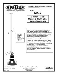
<strong>INSTALLATION</strong> <strong>INSTRUCTIONS</strong><br />
<strong>HUSTLER</strong> 4-<strong>BTV</strong>, 5-<strong>BTV</strong> TRAP VERTICAL<br />
WARNING<br />
<strong>INSTALLATION</strong> OF THIS PRODUCT NEAR POWER LINES IS DANGEROUS<br />
FOR YOUR SAFETY, FOLLOW THE <strong>INSTALLATION</strong> DIRECTIONS<br />
GENERAL DESCRIPTION:<br />
The Hustler 4-<strong>BTV</strong> is a four-band trap vertical antenna providing an omni directional pattern. The 4-<br />
<strong>BTV</strong> is designed as a self-supporting vertical to provide optimum operation in the 10, 15, 20 and 40<br />
meter bands. It can also be adapted to operate in the 75 meter band. This antenna is designed for<br />
installations with restricted space.<br />
The Hustler's 5-<strong>BTV</strong> is a five band trap vertical antenna adding 75/80 meter operation to the 4-<strong>BTV</strong>.<br />
This is achieved by adding the RM-80S resonator and 4457-1 spider assembly (see diagram page 3).<br />
The Hustler 4-<strong>BTV</strong> provides electrical selection of bands through the use of optimum Q traps, which are<br />
individually and precisely tuned and internally sealed at the factory. Tampering with the traps will<br />
render your warranty null and void. The traps are parallel tuned circuits which provide efficient isolation<br />
between the vertical sections, permitting multi-band operation. Broadband operation over the entire ham<br />
band at very low SWRs is possible in a proper installation. Operation in the 75/80 meter band is<br />
provided by installing the appropriate resonator on top of the 4-<strong>BTV</strong>.<br />
The Hustler 4-<strong>BTV</strong> was designed to provide optimum performance from both an electrical and<br />
mechanical standpoint. Mechanically, this antenna boasts a heavy duty base and heavy duty aluminum<br />
tubing. The mechanical assembly is accomplished with all stainless steel hardware. The use of clamps<br />
permits readjustment if necessary, and allows individual peaking of each band. The mechanical<br />
construction is such that guying is not ordinarily needed. If the 75 meter resonator is attached to the 4-<br />
<strong>BTV</strong>, it may be desirable to guy the antenna above the 20 meter trap with small diameter polypropylene<br />
rope.<br />
The performance provided by the Hustler 4-<strong>BTV</strong> is better than any other antenna of this type. Broad<br />
banding is such that one measurement and setting permits both phone and CW operation. The antenna<br />
provides a nominal 52 ohm base impedance when installed and tuned according to the instructions. The<br />
radiation efficiency is equivalent to, or greater than, other trap verticals.<br />
STEP-BY-STEP ASSEMBLY:<br />
1. Check the parts against the package contents listed on the following page.<br />
2. Install mounting bracket on the support mast or stake. Tighten "U" bolts securely. Use lock<br />
washers and 1/4"-20 hex nuts (heavy nuts). Use 1-1/4" I.D. water pipe or other very strong<br />
support.<br />
3. Accurately cut radial lengths (if needed or desired) in accordance with radial length table (Fig.<br />
6).
PACKAGE CONTENTS<br />
Qty. Part Number<br />
1 4098-1 Bracket Assembly<br />
1 4190 Top Tube Section<br />
1 4087-1 Lower Tube Section<br />
2 4087-2 Intermediate Tube Section<br />
1 4090-1 Ten Meter Trap<br />
1 4090-2 Fifteen Meter Trap<br />
1 4090-3 Twenty Meter Trap<br />
6 5481 Spider Tubes<br />
1 4198 Accessory Kit Consisting of the Following:<br />
IN PLASTIC BAG<br />
7 3152-4 Clamp, #12, SS<br />
2 3488-6 "U" Bolts<br />
4 2491-5 Lock washers 1/4" Split<br />
1 3609-5 Spider Hub<br />
1 2194-15 Screw 6-32 x 3/4"<br />
1 2382-1 Nut Hex, 10-32 SS<br />
7 2832-31 Nut Hex, 6-32 SS<br />
4 2832-32 Nut 1/4-20 x 7/32" Thick<br />
1 4513 Terminal Lug 1/4" Hole<br />
1 4514 Terminal Lug #10 Hole<br />
6 3162-9 Flat Head Screw 6-32 x 5/8"<br />
2 2233-41 Washer 1/2" O.D. x 3/16" I.D.<br />
7 2381-16 Lock washer Ext. #6 SS<br />
1 6099 Danger Label<br />
IN PLASTIC BAG FOR RADIAL MOUNTING<br />
2 2700-7 Hex Head Bolt 1/4-20 x 1-1/2"<br />
8 2233-16 Washers 5/8" O.D. x 1-1/4" I.D.<br />
2 2491-5 Lock washer 1/4"<br />
2 2832-32 Nuts 1/4-20 x 7/32" Thick
4260-1<br />
Nut 2382-31<br />
(1)<br />
Plastic Cap<br />
5303-1<br />
Stud 5648<br />
For 75 Meter<br />
Resonator<br />
Spider Assembly<br />
Spider Tubes<br />
5481 (6)<br />
Spider Hub<br />
3609-5<br />
Lockwasher<br />
2381-16 (1)<br />
Alum. Tube and<br />
Plug Ass'y<br />
4100<br />
Insulator 4478<br />
Gasket 9433<br />
Lockwasher 2491-5 (2)<br />
Nut 2382-32 (2)<br />
Screw 4405-1 (3)<br />
Lockwasher 2381-10 (1)<br />
Lockwasher 2491-5 (2)<br />
Nut 2382-32 (2)<br />
Lockwasher 2381-10 (1)<br />
Nut 2382-1 (3)<br />
Washer 2233-41 (2)<br />
Lug 4514<br />
Washer 2233-41<br />
Lockwasher 2381-10 (2)<br />
Nut 2382-1 (1)<br />
Lockwasher<br />
2381-10 (6)<br />
Screw 2893-7 (3)<br />
Washer 2233-48 (3)<br />
Insulator 3002<br />
Washer 2233-33 (2)<br />
Lockwasher 2491-5 (1)<br />
Washer 2233-33 (1)<br />
Lug 4513<br />
Washer<br />
2233-33 (1)<br />
Screw<br />
2893-13 (1)<br />
Nut 2382-32 (2)<br />
Screw<br />
3162-9 (6)<br />
Screw 2194-15<br />
U-Bolt<br />
3488-6 (2)<br />
Washer 2381-10 (3)<br />
Nut 2382-1 (3)<br />
Bracket 4342-2<br />
Washer 2233-16 (8)<br />
Lockwasher<br />
2491-5 (2)<br />
(RM 75/80S<br />
Resonator)<br />
5-<strong>BTV</strong> only<br />
Top Tube<br />
Section 4190 1-1/4" x 56"<br />
Plastic Cap 4082<br />
20 Meter Trap<br />
4090-3 GREEN<br />
Clamp 3152-4 (7)<br />
Intermediate<br />
Tube<br />
Section 4087-2<br />
Plastic Cap 4082<br />
Three Bladed<br />
Spider Assembly<br />
4457-1<br />
15 Meter Trap<br />
4090-2 RED<br />
Factory Adjusted Traps<br />
Do Not Loosen Clamps<br />
Intermediate Tube Section 4087-2<br />
1-1/4" x 20"<br />
Plastic Cap 4082<br />
10 Meter Trap<br />
4090-1 ORANGE<br />
Lower Tube Section 4087-1<br />
Radial Terminations<br />
Bolt 2700-7 (2)
Figure 4<br />
Figure 5<br />
Solder on the size<br />
lugs as indicated above.<br />
Tape tightly with plastic<br />
electrical tape.<br />
After installing coat with sealant<br />
20 Meter Trap<br />
No. 6-32 x 3/4” Screw<br />
Nut 2382-1<br />
Lug with 3/16”<br />
dia. Hole on<br />
shield end.<br />
Lug with<br />
1/4” dia.<br />
hole on<br />
side.<br />
3/8” dia. X 13”<br />
Alum. Tubes (6)<br />
6-32 x 5/8” Screw (6)<br />
Nut 2382-1 (6)<br />
Figure 3<br />
Draw center conductor out<br />
with an awl or dull pointed<br />
instrument.<br />
must be<br />
UP<br />
This<br />
Surface<br />
D”<br />
Figure 2<br />
Separate strands of braid with an awl<br />
being careful not to break any.<br />
Recommended Method of Preparing Coax
Illustrations Showing Feed<br />
Line and Radials Connections<br />
Radial Length Table<br />
Radial Lengths for<br />
4 Band Operation<br />
2 Each Required<br />
10 Meters<br />
15 Meters<br />
20 Meters<br />
40 Meters<br />
8' 4"<br />
11' 4"<br />
16' 4"<br />
32' 4"<br />
Nut 2382-1 10-32 (3)<br />
4260-1<br />
Washer 1/2" O.D. x<br />
3/16" I.D. (6)<br />
Shield<br />
Hot<br />
Shield<br />
Radials<br />
(not supplied)<br />
Hot<br />
Figure 6<br />
Lockwasher #2491-5<br />
Radials<br />
(not supplied)<br />
Thick Hex Nut<br />
1/4 - 20x7/32<br />
Washer #2233-33<br />
Screw #2893-13<br />
1/4-20 x 1-1/2<br />
hex head bolts<br />
4 washers 5/8 o.d.<br />
1 lockwasher 1/4"<br />
1 hex nut 1/4-20<br />
Lock washer #2491-5
4260-1<br />
Dimensions A,B & C<br />
are measured from<br />
these points<br />
Dimension Table<br />
Approximate dimensions<br />
Type of Installation A B C D<br />
On a roof with 4 foot<br />
pipe and radials<br />
On a metal tower with<br />
radials dropped 45 degrees<br />
On ground with radials<br />
On ground without radials<br />
Never loosen<br />
the trap clamp<br />
2 - 1/8 2<br />
The above dimensions are in inches.<br />
Tuning may be necessary to obtain resonance at desired frequency.<br />
2<br />
1<br />
0<br />
Figure 7<br />
2<br />
1 - 5/8<br />
1/2<br />
1 - 7/8<br />
1 - 1/8<br />
1 - 1/16<br />
1 - 1/16<br />
61-1/8<br />
61-1/8<br />
62-1/8<br />
62-1/8<br />
D<br />
Measured from top<br />
surface of spider<br />
casting to top of<br />
cap on tube<br />
20 Meter Trap<br />
C<br />
20" Tube<br />
C<br />
15 Meter Trap<br />
20" Tube<br />
A<br />
A<br />
B<br />
B<br />
10 Meter Trap<br />
72" Tube<br />
4"
4. Prepare split lead on coax in accordance with Figure 2 and 3. RG-8U coax is recommended.<br />
5. Install lugs on coax as shown in Figure 4 and weatherproof with electrical tape.<br />
6. Install coax feed line and radials as shown in Figure 6.<br />
7. After making all connections to the mounting bracket, a heavy protective coating such as Krylon<br />
clear spray would be very advantageous.<br />
8. Assemble the 3/8" x 13" tubes to the hub as shown in Figure 5, using the 6-32 machine screws,<br />
number 6 lock washers and the 6-32 hex nut.<br />
9. Install the 10 meter trap to the 1-1/4" x 72" tube, using one of the clamp assemblies. Set to<br />
dimension A and table in Figure 7, the measurement should be made at the end of the long tube and<br />
the bottom edge of the trap. Securely and carefully tighten the clamp.<br />
IMPORTANT<br />
THE PLASTIC CAP IS THE TOP OF THE TRAP AND MUST BE INSTALLED IN THAT<br />
POSITION, THE CLAMP AT THE BOTTOM OF THE TRAP SHOULD NOT BE<br />
LOOSENED. THIS WOULD UPSET TRAP CALIBRATION.<br />
10. Install #12 clamp at each end of one of the 1-1/4" x 20" tubes and slide over the tube of the 10 meter<br />
trap. Install the 15 meter trap in the opposite end of the same tube and set both dimensions B from<br />
table in Fig. 7. The measurement should be made from the upper most edge of the plastic cap to the<br />
bottom edge of the 15 meter trap. Securely tighten clamps.<br />
11. Install the second 1-1/4" x 20" tube, complete with clamps, on the 15 meter trap and then install the<br />
20 meter trap in the top of that tube. Set to dimension C from the table in Fig. 7, again measuring<br />
from the top of the plastic at the bottom of the tube, and from the top of the tube to the bottom edge<br />
of the trap.<br />
12. Install spider assembly as shown in Fig. 5, it should be flat against the top of the 20 meter trap cover.<br />
Securely tighten the 6-32 x 3/4" screw with lock washer and hex nut.<br />
13. Install the 1-1/4" x 56" tube to the 20 meter trap and set to dimension D from table in Fig. 7.<br />
Securely tighten clamps.<br />
14. Each clamp should be installed near the edge of the tubing to obtain the best mechanical and<br />
electrical connection. Re-check all bolts to insure tightness. Re-check all dimensions against table in<br />
Fig. 7.<br />
15. Install assembled antenna on mounting bracket and set the bottom dimension A, from table in Fig. 7,<br />
and securely tighten clamps. Never allow the mast on which a 4-<strong>BTV</strong> is mounted to extend above<br />
the bracket.
<strong>INSTALLATION</strong>:<br />
READ THE ATTACHED SAFETY WARNING ON LAST TWO SHEETS BEFORE<br />
PROCEEDING FURTHER<br />
An important part of any vertical antenna is its ground plane. While the Hustler 4-<strong>BTV</strong> was designed<br />
as a space saver, we recommend one of the following installations from a performance viewpoint.<br />
1. For optimum performance, roof mount with radials. Roof mounting of the antenna will provide<br />
height which, in turn will generally provide better transmission and reception.<br />
The 4-<strong>BTV</strong> can be mounted on a ground mounted tower, heavy duty chimney clamp, wooden<br />
pole, short roof mounted tower or other suitable support assembly. Try to locate the antenna<br />
10-15 feet away from non-metallic structures.<br />
CAUTION: Mounting the 4-<strong>BTV</strong> on towers, tripods, or large mast pipes, approximately a<br />
quarter wave in length, can often provide an upset to the counterpoise created by the radial<br />
system, and act as a vertical dipole instead of the desired ground plane. To correct this<br />
problem, the radial system must be R.F. isolated from the mounting structure. This may be<br />
done by using a non-conductive mounting mast, such as heavy wall fiberglass tube or<br />
fiberglass rod or by sliding a split piece of PVC pipe over the metal mast. The coax or<br />
mounting bracket should not be directly grounded.<br />
The 4-<strong>BTV</strong> installation is most easily accomplished by installing the base only to your support<br />
assembly. After connecting radials and feedline to the base, the 4-<strong>BTV</strong> can be attached to the<br />
base.<br />
Using the radial length table (Fig. 6) install two insulated wire radials for each band used. It is<br />
recommended that the radials be constructed of large diameter insulated wire, 14 gauge is<br />
usually ample.<br />
When radials are installed they should be equally spaced around 360 degrees with radials of<br />
equal length opposite each other. Never bunch radials as one will detune the other. They should<br />
be attached to the base mount in accordance with Figure 6.<br />
Care should be taken to make a good electrical connection at the antenna bracket. When radials<br />
are used in a roof mount configuration, every attempt should be made to permit a 45 degree<br />
droop angle below horizontal.<br />
This is accomplished by choosing a mounting pipe or short tower long enough to make these<br />
angles possible. If space is limited, some compromise is permissible providing the droop angle<br />
is held between 10-60 degrees below horizontal with radials fanned out as much as possible.<br />
If space is severely restricted, radials may be zigzagged or run in an "L" configuration avoiding<br />
near parallel wrap back less than 90 degrees.
1. The importance of the ground system cannot be over-emphasized. The ground or radial<br />
system must be considered as half the antenna.<br />
When radials are used, high impedance will exist at the ends of the radials, and adequate<br />
insulation must be provided, or their purpose will be defeated. Tie them off using a nonconductive<br />
material such as polypropylene rope or heavy gauge fishing line. In a case<br />
where the antenna or the radials are mounted over or near metallic objects the radials<br />
must be insulated or mounted at least 4 in. over the roof.<br />
2. Second Choice, ground mount with radials; if you are unable to mount the antenna in the<br />
preferred roof mount configuration, the second best choice would be that of ground<br />
mounting. In ground mounting it is important to choose a location reasonably free from<br />
obstructions such as houses, metal fences, trees, wires, vertical downspouts, aluminum<br />
siding, other antenna, etc. Try to maintain at least a radius of 10-15 feet of clear area<br />
around the antenna. It is recommended that the 4-<strong>BTV</strong> be mounted on a 4 foot metal<br />
stake such as a 1-1/4" I.D. Water pipe. Do not exceed this length. This stake should be<br />
buried in the ground with 18 inches left protruding. (Do not concrete or put into a pre-dug<br />
hole. Drive it into the ground.) Position the 4-<strong>BTV</strong> base on this pipe to a location not<br />
exceeding four inches of separation between earth and coax connection. Do not try to use<br />
a network of ground rods around the base of the antenna. If the ground supplied by this<br />
pipe is not sufficient, radials must be employed.<br />
The radials in this type of installation will provide a better overall performance than that<br />
of stake mount only. Ground mount radials may be either buried a couple of inches below<br />
the surface or left on top of the ground. If they are left on unburied, power equipment<br />
(such as lawnmowers) or pedestrian traffic could become entangled in the wires.<br />
Using the radial length table, Fig. 6, install two insulated radials for each band. It is<br />
recommended that the radials be constructed of large diameter wire; #14 gauge is usually<br />
sufficient. The radials should be spaced around the base 360 degrees with radials of equal<br />
length opposite each other. Never bunch radials, as one will detune the other. They<br />
should be attached to the base mount in accordance with Figure 6. Any wire droop on the<br />
ground need not be of concern.<br />
Least Desirable, ground mount without radials. If you do not have sufficient space and are<br />
unable to use a ground radial system, ground mounting of the antenna on a 4 foot ground stake<br />
driven into the ground with only 18 inches protruding, will provide good performance, which in<br />
turn, will be in direct ratio to the ground conductivity and soil conditions in your particular area.<br />
In ground mounted location, performance (SWR, bandwidth and radiation efficiency) is directly<br />
related to ground conductivity. If the ground conductivity is good, you obviously will obtain<br />
better results. As stated previously, the 4-<strong>BTV</strong> was expressly designed to give you satisfactory<br />
performance even in this configuration. Therefore, if ground mounting without radials is a<br />
necessity, you can still obtain better performance from the 4-<strong>BTV</strong> than obtainable from any<br />
similar antenna.<br />
NOTE: Adding more pairs of radials than the 2 per band prescribed in instructions, may result in<br />
obtaining better results for DX'ing.
Favorable soil conditions can be a reason that sometimes a ground mount using the soil as a<br />
ground plane may result in better DX'ing than a roof mount using only a pair of radials per<br />
band.<br />
TUNING FOR ALL CHOICES:<br />
The dimensions given in the table are approximate and will vary, depending on environment. To check<br />
antenna tuning, use a sensitive SWR bridge. (DO NOT USE A FIELD STRENGTH METER.) Using<br />
only sufficient power to obtain a full scale reading, check and record the SWR at the high, center and<br />
low edge of the bands. If the SWR reading is lowest at the high end, lengthen the related section of the<br />
antenna; if it is lowest at the low end, shorten this antenna section. Always attempt to get the very<br />
lowest SWR reading in the center of the band. Tuning in this manner will permit operation in both the<br />
phone and CW portions with a low SWR. If you favor one end of the band or the other, you can retune<br />
the antenna to provide the lowest SWR in that portion, if desired.<br />
In the process of tuning the antenna, it is mandatory that you always start with 10 meters and work<br />
your way up the antenna. Tune 10 first, then 15, 20 and 40 meters. Any adjustments made on 10 will<br />
affect the other bands. Any adjustment made on 15 will affect 20 and 40. By the same token, any<br />
adjustments on 20 will affect 40. Adjustment of the individual bands is as follows: 10 meters, adjust<br />
dimension A; 15 meters, adjust dimension B; 20 meter, adjust dimension C; and 40 meters, adjust<br />
dimension D.<br />
It is not necessary to remove the bracket each time to adjust the antenna. It is only necessary to remove<br />
the antenna from the bracket. (If the desired SWR cannot be achieved, it is probably because of an<br />
insufficient counterpoise system or poor soil conditions.)<br />
If resonance can be adjusted properly but a low SWR cannot be reached, then it is probably due to<br />
insufficient insulation at the ends of the radials, improper angle of the radials, or reflections from<br />
nearby resonant objects. A number of conditions may cause the resonance to shift from the factory<br />
dimensions occasionally to the point that resonance cannot be reached within the normal range of<br />
adjustment; lengthening or shortening the radials may help to compensate for these conditions.<br />
Changing coax length or adjusting a tuner may make the SWR appear better but will not change the<br />
antenna, the final radiator, or its performance. When the antenna is tuned properly at resonance, little<br />
change in SWR will occur regardless of where the bridge is located in the line.<br />
Never use an antenna tuner to tune the 4-<strong>BTV</strong>. Proper tuning of this antenna requires the 4-<strong>BTV</strong><br />
sections. Use of a tuner only fools the transmitter and does not correct a problem at the antenna. The<br />
antenna system must be tuned properly at the antenna to radiate efficiently.<br />
Filters should never be used in a coax line while trying to tune an antenna.
1ADDING 75/80 METER CAPABILITY<br />
1. With reference to Figure 7, mark the location at the bottom of the dimension “A” and remove<br />
the 4-<strong>BTV</strong> from its base by loosening the lowest stainless steel clamp.<br />
2. If your installation is elevated, two radials are required at the following lengths. If space is<br />
restricted, radials may be zigzagged or run in an “L” configuration avoiding near parallel wrap<br />
back. Phone Band: 75 meter resonator – 64ʼ 4”, CW Band: 80 meter resonator – 65ʼ 6”.<br />
3. Install a spider assembly, part #4457-1, after bending the three spider arms as illustrated in<br />
Figure 1 on the top of the 56” upper tube section just below the 75 and 80 meter resonator.<br />
4. Determine and set approximate tip rod length from Figure 8 for your desired band location.<br />
Tighten tip rod locking nut securely and attach resonator to 4-<strong>BTV</strong>.<br />
5. Replace the 4-<strong>BTV</strong> on the mounting bracket to its original “A” dimension.<br />
6. Check performance with SWR bridge. Minor adjustment (lowest SWR) may be required on the<br />
tip rod length to establish resonance at the desired 75 or 80 meter frequency.<br />
7. Reactance of the resonator may cause slight change in 40 meter resonance. This is easily<br />
corrected by adjusting element dimension “D”, Figure 7.<br />
TIP ROD LENGTHS FOR 75 OR 80 METER RESONATORS USED WITH 4-<strong>BTV</strong><br />
Tip rod length measured from top of tip ball down to top of clutch locking nut as illustrated.<br />
NOTE: All resonators are supplied with tip rod lengths for mobile operation. With the 4-<strong>BTV</strong>, a<br />
shorter length is required, therefore, remove the tip rod from the resonator and grind off the necessary<br />
amount from the end that inserts in the resonator. Before cutting ascertain the approximate rod length<br />
from the chart plus no less than 4 inches for insertion in the upper tube section of the resonator.<br />
DIMENSIONS INDICATED ARE APPROXIMATE<br />
FREQUENCY (KHz.) RM-75-S RM-75<br />
RM-80-S RM-80<br />
4000 18” 21-1/4”<br />
3950 19-5/8” 22”<br />
3900 21” 22-1/2”<br />
3850 22-1/2” 23-3/4”<br />
3800 24-1/8” 24-3/4”<br />
3750 25-5/8” 26”<br />
3725 26-1/2” 26-3/4”<br />
(Novice Band) (Novice Band)<br />
3700 27-1/4” 27-3/4”<br />
3650 29” 29-1/4”<br />
3600 30-5/8” 31”<br />
3550 33” 33”<br />
3500 34-5/8” 34-3/4”<br />
The above dimensions are exposed lengths of tip rod.<br />
4260-1<br />
Tip Rod<br />
Length<br />
Add 4” for<br />
Tip Rod Insertion<br />
into Tube
GUYING<br />
The 4-<strong>BTV</strong> is designed as a self-supporting vertical. However, if your area encounters severe<br />
wind velocities or icing conditions, simple guying will prevent the possibility of failure.<br />
Attach a small diameter polypropylene rope just above the 20 meter trap. The polypropylene<br />
rope should ultraviolet (UV) stabilized and weather resistant. Guying should be tightened just<br />
enough to permit the antenna to swing in a two to three degree arc. If a 75 or 80 meter resonator<br />
is included in your installation, use guying.<br />
RADIALS<br />
Radials should be made from insulated wire of #14 gauge or larger, insulating the bare ends of wire<br />
on the outer end of the radials. A minimum of two radials per band is required.<br />
RADIAL LENGTHS ARE AS FOLLOWS<br />
10 Meters 8' 4"<br />
15 Meters 11' 4"<br />
20 Meters 16' 4"<br />
40 Meters 32' 4"<br />
75/80 Meters 64' 4"<br />
4260-1<br />
Normal Configuration Limited Space Configurations
NEW-TRONICS ANTENNA CORPORATION LIMITED WARRANTY<br />
<strong>New</strong>-<strong>Tronics</strong> Antenna Corp. warrants its products to be free of defects in material and workmanship<br />
and extends this warranty under intended use and normal service conditions to the original owner for a<br />
period of one year from the date of purchase. This warranty does not apply to any product that has<br />
been repaired or altered in any manner and is void for any damage due to accident, neglect,<br />
unreasonable use, improper installation, or any other cause not arising out of defects in material or<br />
workmanship.<br />
The obligations of <strong>New</strong>-<strong>Tronics</strong> Antenna Corporation are limited to repairing or replacing, at its<br />
option, any product or part that is returned to the factory; all transportation charges prepaid,<br />
accompanied by proof of purchase, and upon examination reveals to have been defective within the<br />
warranty period stated above.<br />
<strong>New</strong>-<strong>Tronics</strong> Antenna Corp. does not assume nor is any person authorized to assume for it, any<br />
obligations other than that herein stated. Any implied warranties, including but not limited to fitness<br />
for a particular purpose, is limited in duration for the above one year period. <strong>New</strong>-<strong>Tronics</strong> Antenna<br />
Corp. shall not be liable under this warranty, or any implied warranty, for loss of use of the product or<br />
for other consequential loss or damage incurred by the purchaser. Some states do not allow the<br />
exclusion or limitation of implied warranties of consequential damages and so the above exclusions or<br />
limitations may not apply in those states. This warranty gives you special legal rights and you may<br />
have other rights that vary from state to state.<br />
<strong>New</strong>-<strong>Tronics</strong> Antenna Corp.<br />
One <strong>New</strong>tronics Place<br />
Mineral Wells, TX 76067-9563<br />
940-325-1386
DECOUPLING YOUR TRANSMISSION LINE<br />
Since your coax shield is connected to where a radial would connect, it too will act as a radial. This is<br />
not desirable since this imposes additional currents which will detract from the antennas low SWR at<br />
the rig end of your coax.<br />
To prevent this from occurring, form at the base of the antenna or within eight feet of the base, a coil<br />
in your coax. By wrapping your coax in a single layer fashion, ten times around a 6" diameter form,<br />
you will form an RF choke in the braid which will isolate these additional currents from your coax.<br />
Since your coax (the shield) is in the R.F. near field of your antenna, it will act as a collector of R.F.<br />
energy (an antenna). This too is not desirable since this can impose similar additional currents which<br />
will register as a higher SWR at the rig.<br />
To prevent this, form the same type coil as before at/or within eight feet of your rig.<br />
These coils will NOT impede the RF energy contained inside the coax from flowing. It only acts as a<br />
high impedance to the undesirable additional currents on the outside braid of your coax.<br />
After having installed these coils, you may need to retune the antenna.<br />
If you still have a high SWR, perhaps tuned radials are needed.<br />
Not to<br />
Exceed 8'<br />
4260-1<br />
10 Turns<br />
6" Dia.<br />
Any Length 50 OHM Cable<br />
10 Turns<br />
6" Dia.<br />
Not to<br />
Exceed 8'