
You also want an ePaper? Increase the reach of your titles
YUMPU automatically turns print PDFs into web optimized ePapers that Google loves.
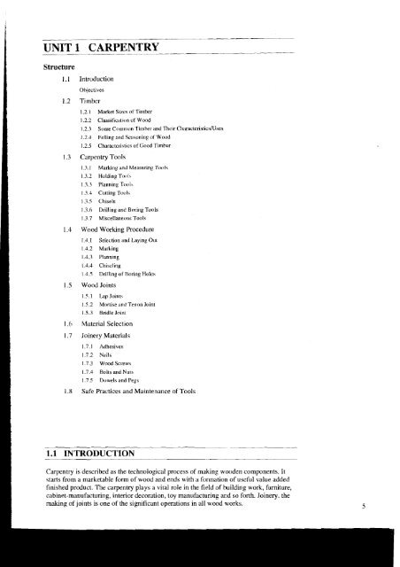
<strong>UNIT</strong> 1 .- . <strong>CARPENTRY</strong><br />
Structure<br />
1.1 Introduction<br />
Objectives<br />
1.2 Timber<br />
1.2.1 Market Sizes of Tiniber<br />
1.2.2 ClassificiiLion of Wood<br />
1.2.3 Some Common Timber and Their Characteristics~ses<br />
1.2.4 Felling and Seasoning of Wood<br />
1.2.5 Character-istics of Good Timber<br />
1.3 Carpentry Tools<br />
1.3.1 Marking and Measuring 7'ot)ls<br />
1.3.2 Holding Tool\<br />
1.3.3 Planning T(:cll\<br />
1.3.1 Cutting Touls<br />
1.3.5 Chisels<br />
1.3.6 Drilling and Boring Tools<br />
1.3.7 Miscellanec~us Tools<br />
1.4 Wood Working Procedure<br />
1.4.1 Selection and Laying Out<br />
1.4.2 Marking<br />
1.4.3 Planning<br />
1.4.4 Chiscling<br />
1 4.5 Drilling of Boring Holes<br />
1.5 Wood Joints<br />
I 5.1 Tap Joints<br />
1.5.2 Mortise and Tenon loint<br />
1.5.3 Bridle loint<br />
1.6 Aljaterial Selection<br />
1.7 Joinery Materials<br />
I .7.1 Adhesives<br />
1.7.2 Nails<br />
1.7.3 Wood Screws<br />
1.7.4 Bolts and Nuts<br />
1.7.5 Dowels and Pegs<br />
1.8 Safe Practices and Maintenance of Tools<br />
Carpentry is described as the technological process of making wooden components. It<br />
starts from a marketable fonn of wood and ends with a formation of useful value added<br />
finished product. The carpentry plays a vital role in the field of building work, furniture,<br />
cabinet-manufacturing, interior decoration, toy manufacturing and so forth. Joinery, the<br />
making of joints is one of the significant operations in all wood works.
Workshop Technology Objectives<br />
Laboratory<br />
After going through this chapter you must be able to<br />
1.2 TIMBER<br />
understand the process of converting timber to wood,<br />
identify and apply all the tools of carpentry,<br />
perform all carpentry operations such as marking, planing, cutting,<br />
chiseling, and finishing,<br />
make various types of joints, and<br />
make different types of wooden patterns used for foundrylmoulding.<br />
Timber is the name given to the wood obtained from well grown trees. The trees are cut,<br />
sawn into various sizes to suit the purposes.<br />
The word, 'grain', as applied to wood, refers to the appearance or pattern of the wood on<br />
the cut surfaces. The grain of the wood is a fibrous structure and to make it strong, the<br />
timber must be so cut, that the grains run parallel to the length.<br />
1.2.1 Market Sizes of Timber<br />
Timber is sold in the market in various standard shapes and sizes. The following are<br />
common shapes and sizes :<br />
Log<br />
Block<br />
Post<br />
Plank<br />
Board<br />
Batten<br />
The trunk of the tree, free from branches.<br />
The log, sawn to have roughly squarelrectangular cross-section.<br />
A round or square cross-section timber piece with diameter or side, varying from<br />
175 to 300 mrn.<br />
A sawn timber piece, with more than 275mm in width, 50 to 150 in thickness and<br />
2.5 to 6.5 meters in length.<br />
A timber piece sawn below 50 mm thickness and more than 125 mm in width.<br />
A timber piece swan below 175 mm in width and 30 to 50 mm in thickness.<br />
Scantlings or Reapers<br />
Beadings<br />
Sawn timber pieces of assorted and non-standard sizes those may not confirm to<br />
the above shapes and sizes.<br />
Assorted timber pieces with small thickness with rectangular or square or any<br />
designed cross section intended to use as the borders and frames.<br />
1.2.2 Classification of Wood<br />
Woods are generally classified into two broad categories : Soft woods and Hard woods.<br />
Hard and Soft Wood<br />
Hard wood is generally obtained from a tree with deciduous or broad leaves<br />
whereas the soft wood from trees having middle shaped conifers.
Examples<br />
Hard Woods<br />
Soft Woods<br />
Teak, Sal, Oak, Shisham, Beach, Ash. Mango, Neem and Babul.<br />
Conifers, Kari, Deodar, Chir, Walnut, etc.<br />
Soft wood is light in colour and weight. It is easy to work on soft wood, but it is<br />
less durable. Hard wood is dark in colour and heavy in weight. It is very difficult<br />
to work on hard wood, but it is highly durable.<br />
Differences between Hard and Soft Wood<br />
1<br />
S1. No.<br />
1.<br />
2.<br />
3.<br />
4.<br />
5.<br />
6.<br />
7.<br />
8.<br />
9.<br />
10.<br />
1.2.3 Some Common Timber and their Characteristics~Uses<br />
The common type of well recognised timber available in India is Shisham, Sal, Teak,<br />
Deodar, Mango, Mahogany, Kail, Chid, Babul, etc. Some of the other foreign wood used<br />
in India is Ash, Burma, Hickory, Oak, and Pine.<br />
Shisham<br />
Sal<br />
It is dark brown in ccilour and possesses goldenldark brown stripes. It is very hard<br />
to work. It wears or blunts the sharp edge of cutting tool very soon. It is abundant<br />
in India in Himalayas at the height range of 1000 to 1500 meter and in deep<br />
forests. It is highly strong durable wood and is mainly used for making of<br />
furniture, tool handles, beds, cabineta, plywood, etc.<br />
It is in rose brown colour and slowly turns into dark brown colour. This is highly<br />
available in India in H~malayas, Madhya Pradesh, Chatthis Garh and Uttar<br />
Pradesh. Tt is free from attack of white ants and is very difficult to work. It has<br />
poor finish and therefore is not used for decorative furniture but it finds<br />
applications in making doors, windows, cot?, wooden handles where finish is not<br />
important.<br />
Teak Wood<br />
Characteristics<br />
Colour<br />
Weight<br />
Density<br />
Resin Content<br />
Ab~lity to Split<br />
Workability<br />
Annual Rings<br />
Tensile and Shear<br />
Resistance<br />
Fire catching<br />
Growth<br />
Tt is the most common wood used in variety of applications. This wood is<br />
abundantly available in Andhra kadesh, Madhya Pradesh, Chatthis Garh, Orissa,<br />
West Bengal and Assam. It is mainly used for making good quality of furniture,<br />
Constructions (doors/windows), plywood, ships, etc. This wood is supposed as the<br />
KING of woods. Some of it? features are :<br />
(a) Hard,<br />
Hard Wood<br />
Dark<br />
Heavy<br />
Denser<br />
Less<br />
Does not split quickly<br />
Difficult<br />
Close and indistinct<br />
Good tensile and shear<br />
resistance<br />
Doesn't catch fire soon<br />
Slow growing<br />
Soft Wood<br />
Light<br />
Light<br />
Comparatively light<br />
Few soft wood are resinous<br />
Gets spl~t quickly<br />
Easy<br />
Well spaced and d~stinct<br />
Good tensile resistance but<br />
weak acros3 the fibers<br />
Catches fire very soon<br />
Fast growing<br />
Carpentry<br />
(b) Very costly but wide appllcat~ons. 7
Workshop Technology<br />
Laboratory<br />
(c) It is available in golden yellow or dark brown colour,<br />
(d) Special stripes on it add to its beauty,<br />
(e) Very strong and durable, and<br />
(f) It maintains good polish.<br />
Deodar<br />
It is white in colour when soft but turns to light yellow as it becomes hard. It is<br />
strong and durable. It provides fragrance when smelt. It is not easily attacked by<br />
insects. Its common availability is in Himalayas at a height from 1500 to 3000 mts.<br />
It is used for making furniture, windows, etc.<br />
Mango<br />
It is Brown in colour and can be easily shaped in various products. It is widely<br />
used in India for making doors packing cases, toys, etc. as a chief products.<br />
Mahogany<br />
It is reddish brown in colour and is highly durable when dry? It also contains some<br />
oil that prevents it from the attack of insects. It is generally used for manufacturing<br />
cabinet, fine furniture, pattern making work, etc.<br />
Kail<br />
This wood possesses too many knots. It is commonly found in Himalayas. It yields<br />
a close grained moderately hard and durable wood which can be easily painted. It<br />
is commonly utilized for making cheap furniture, wooden door, paclung case, etc.<br />
Chid or Chir<br />
Its colour is dark brown when soft, but it is reddish brown when hard. It has stripes<br />
of brown colour. It has oily smell and is used for interior work in the house.<br />
Babul<br />
It is close grained tough and pale red coloured wood used for making tool handles,<br />
etc.<br />
Fir Wood<br />
It is light brown in colour when it is soft but harder variety is in dark brown. It can<br />
be easily attacked by insects. It is commonly utilizes for making drawers, packing<br />
cases door, etc.<br />
Walnut<br />
It is a good variety of wood which resists the attack of white ants. It can be<br />
polished in a better way. This wood is generally used for making musical<br />
instruments, furniture cabinet work, and decoration work.<br />
Haldu<br />
It is white in colour at the time of cutting, but once cut, its colour becomes yellow.<br />
It can be dried polished satisfactorily. It is widely used for making small objects<br />
such as stools, trays, picture frames, cabinets, etc.<br />
Neem<br />
This is whitish brown in colour and is free from white ants and insects. It is<br />
comparatively hard. It has poor finish ability. Widely available in Andhra Pradesh,<br />
Deccan plateau and Mid-India.<br />
1.2.4 Felling and Seasoning of Wood<br />
Conversion of tree into timber or wood logs is called felling. A newly felled tree contains<br />
considerable moisture content. If this is not removed, the timber is likely to wrap, shrink,<br />
crack or decay. Seasoning is the art of extracting the moisture content under controlled<br />
conditions, at a uniform rate, from all parts of the timber. Only seasoned wood should be
used for all carpentry works. Seasoning makes the wood resilient and lighter. The<br />
seasoning is carried out into two ways, viz. Natural seasoning and artificial seasoning.<br />
Hot air or water is used for seasoning.<br />
1.2.5 Characteristics of Good Timber<br />
A good timber should<br />
(a) Have minimum moisture content, i.e. it should be well seasoned.<br />
(b) Have straight and long grains.<br />
(c) Retain its straightness after seasoning.<br />
(d) hoduce a characteristic sound (nearly metallic) on hammering.<br />
(e) Be free from defects such as knots, cracks, rind galls, shakes and twists.<br />
(0 Have uniform colour throughout.<br />
(g) Respond well to the finishing and polishing operations.<br />
(h) Not split easily during driving the nails and screws.<br />
1.3 <strong>CARPENTRY</strong> TOOLS<br />
--<br />
The following are the tools used in wood working operations :<br />
1.3.1 Marking and Measuring Tools<br />
To produce parts to exact size we need to do marking first. To transfer dimensions onto<br />
work; the following are the marking and measuring tools that are generally used in<br />
carpentry.<br />
Steel Rule<br />
Steel Tape<br />
It is an important tool for linear measurement and can also be used as a marking<br />
tool.<br />
Figure 1.1 : Steel Rule<br />
It is used for large measurements, such as marlung on boards and checking the<br />
over all dimensional of the work.<br />
Marking Gauge<br />
Marking gauge is a tool used to mark lines parallel to the edge of a wooden piece.<br />
It consists of a square wooden stem with a sliding wooden stem with a sliding<br />
wooden stock (head) on it. On the stem is fitted with a marking pin, made of steel.<br />
The stock is set at desired distance from the marking point and fixed in position by<br />
a screw. It must be ensured that marking pin projects through the stem 3mm and<br />
the end is sharp enough to make a very fine line.<br />
Carpentry
Workshop Technology Mortise Gauge<br />
Laboratory<br />
A mortise gauge consists of two pins. In this, it is possible to adjust the distance<br />
between the pins, to draw two parallel lines on the stock.<br />
(a) Marking Gauge (b) Mortise Gauge<br />
Figure 1.2 : Mortise Gauge<br />
It is used for making and testing the straightness and squareness (perpendicularity)<br />
of planed surfaces. It consists of a steel blade, fitted in a cast iron stock. It is also<br />
used for checking the planed surfaces for flatness. Its size varies from 150 to<br />
300 mm, according to the length of the blade.<br />
Compass and Divider<br />
Testing for<br />
Straightness<br />
Figure 1.3 : Try-square<br />
Testing for<br />
Squareness<br />
These are used for marking arcs and circles on the planed surfaces of the wood.<br />
Scriber or Marking Knife<br />
It is used for marking on timber. It is made of steel, having one end pointed and the<br />
other end formed into a sharp cutting edge.<br />
Compass Divider<br />
Scriber or Making Knife<br />
Blade<br />
Figure 1.4 : Scriber or Marking Knife<br />
It is used for laying-out and checking angles. The blade of the bevel is adjustable<br />
and may be held in place by a thumb screw. After it is set to the desired angle, it<br />
can be used in same way as a try-square. The extra advantage of this over try<br />
square is that it can be adjusted at any angle while try square can check only<br />
perpendicularity only. A good way to set it to the required angle is to mark the<br />
angle on a surface and then adjust the blade to fit the angle.
1.3.2 Holding Tools<br />
Carpenter's Vice<br />
The carpenter's bench vice, used as a work holding device in a carpenter shop. Its<br />
one jaw is fixed the side of the table while the other is movable by means of the<br />
screw and a handle. The jaws are lined with hard wooden faces.<br />
t9 '\,,<br />
Trigger for Qulck Openlng<br />
Figure 1.5 : Carpenter's Vice<br />
C-clamp is used for holding small works.<br />
Bar Clamp *.<br />
A bar clamp as shown in the following figure is made of steel bar of T-section,<br />
with malleable iron fitting and a steel screw. It is used for holding wide works such<br />
as frames or tops.<br />
1.3.3 Planing Tools<br />
Retaining Pin<br />
Figure 1.6 : Bar Clamp<br />
Planing is the operation carried out on wood to produce flat surfaces. A plane is a hand<br />
tool used for this purpose. The cutting blade of a plane is fitted in a wooden or metallic<br />
block, at an angle. This cutting blade used in a plane is similar to a chisel. Different types<br />
of planes used for different purposes are shown here below.<br />
Jack Plane<br />
It is the most commonly used general purpose plane. It is about 30-40 cm lobg.<br />
The cutting blade has a cutting edge of slight curvature for quick removal of<br />
material on rough work and is also used in oblique planning,<br />
I I
Workshop Technology Rebate Plane<br />
Laboratory<br />
It is used for making a rebate. A rebate is a recess along the edge of a piece of<br />
wood, which is generally used for positioning glass in frames and doors.<br />
Blade . .<br />
o- Wood Jock Plane<br />
Lever Cap<br />
. . .. . . .<br />
b - Metal Jack Plane<br />
a -Wood Jack Plane Blade<br />
Blade<br />
c - Smoothing Plane d - Rotate Plane e - Plough Plane<br />
1.3.4 Cutting Tools<br />
Saws<br />
Figure 1.7 : Planing Tools<br />
A saw is used to cut wood into pieces. A saw is specified by length of its toothed<br />
edge. The different types of saws, designed to suit different purposes are shown<br />
below.<br />
Cross-cut or Hand Saw<br />
Rip Saw<br />
It is used to cut across the grains of the stock. The teeth are so set that the saw<br />
kerfs will be wider than the blade thickness for moving free11 during the cut,<br />
without sticking.<br />
It is used for cutting the stock along the grains. The cutting edge of this saw makes<br />
a steeper angle, i.c. about 60" (see figure), where as that of cross cut saw makes an<br />
angle of 45" with the surface of the stock.<br />
Tenon Saw<br />
It is used to cut the stock either along or cross the grains. It is used for cutting<br />
tenons and in fine work. However, it is used for small and thin cuts. The blade of<br />
this saw is very thin and hence it is stiffened with a thick back steel strip. Hence,<br />
this is sometimes called back-saw also. (In fact in back saw, the teeth are shaped<br />
like those of cross-cut saw).<br />
Compass Saw<br />
It has a narrow, longer and btronger tapering blade, which is used for heavy works<br />
(see figure). It is mostly used for radius cutting. The blade of this saw is fitted with<br />
an open type wooden handlc.
1.3.5 Chisels<br />
a - Cross Cut Saw<br />
Am<br />
-?C<br />
b - Cross Cut Saw Teeth<br />
---<br />
['<br />
90. -'\ -t<br />
1 - -<br />
c - RIP Cut Saw Teeth<br />
Handle<br />
Blade<br />
Figure 1.8 : Saws<br />
Chisels are used for cutting and shaping the wood. Chisels used for wood working are<br />
made in various blade widths, ranging from 3 to 50 mm. They are also made in different<br />
blade lengths. Most of the chisels used for wood working are made into tang type, having<br />
a steel shank which fits inside the handle as shown in the figure. These are made of<br />
forged steel or tool steel blades.<br />
Firmer Chisel<br />
Cuttlng Edge<br />
Blade Tang<br />
a - Firmer b - Dovetail c - Mort~se<br />
Figure 1.9 : Chisels<br />
The word 'firmer' means 'stronger' and hence firmer chisel is stronger than other<br />
chisels. It is a general purpose chisel and is used either by hand pressure or by a<br />
mallet. The blade of a firmer chisel is flat, as shown in Figure 1.9.<br />
Dovetail Chisel<br />
Carpentry<br />
It has a blade with a beveled back, as shown in Figure 1.9, due to which it can<br />
enter sharp comers for finishing, as in dovetail joints. 13
Workshop Technology Mortise Chisel<br />
Laboratory<br />
This is used for cutting mortises and chipping inside holes. The cross-section of<br />
the mortise chisel is so proportioned as to withstand heavy blows during mortising<br />
(Figure 1.9). Further, the cross-section is made stronger near the shank.<br />
1.3.6 Drilling and Boring Tools<br />
Carpenter's Brace<br />
Auger Bit<br />
This is used for rotating auger bits, twist drills, etc., to produce holes in wood as<br />
shown in the Figure 1.10. Some braces have ratchet device. With this, holes may<br />
be made in a comer where complete revolution of the handle cannot be made. The<br />
size of a brace is determined by its sweep.<br />
Figure 1.10<br />
It is similar to drill bit and is the common tool used for making holes in wood.<br />
During drilling, the lead screw of the bit guides into the wood, necessitating only<br />
moderate pressure on the braces. The helical flutes on the surface cany the chips to<br />
the outer surface (see Figure 1.1 1).<br />
Hand Drill Carpenter's Brace<br />
Gimlet<br />
Twist<br />
Scoring Nib<br />
Cutting Tip "<br />
Figure 1.11<br />
This is used to make relatively large size holes; while hand drill is used for drilling<br />
small holes. A straight shank drill is used with this tool. It is small, light in weight<br />
and may be conveniently used than the brace. The drill bit is clamped in the chuck<br />
at its end and is rotated by a handle associated with gear and pinion mechanism.<br />
It has cutting edges like a twist drill as shown in the Figure I .12. It is used to drill<br />
holes of large diameter with the hand pressure.
I<br />
i<br />
1.3.7 Miscellaneous Tools<br />
Mallet<br />
Pincer<br />
A mallet made up of wood or rubber is like a hammer used to drive the chisel with<br />
considerable force to be applied, which may be the case in making deep rough cuts<br />
(Figure 1.13). SteeVIron hammer should not be used for the purpose, as it may<br />
damage the chisel handle. Further, it is advisable to apply a seiies of light taps with<br />
the mallet rather than a heavy single blow.<br />
Figure 1.13 : Mallet<br />
It is usually made up of two forged steel arms hinged and is used to pull-out small<br />
nails from wood. The inner faces of the pincer jaws are beveled and the other faces<br />
are plain. The end of one arm has a ball and the other has a claw. The beveled jaws<br />
and the claw are used for pulling out small nails, pins and screws from the wood.<br />
Claw Hammer<br />
Figure 1.14 : Pincer<br />
It has a striking flat face at one end and the claw at the other, as shown in the<br />
Figures 1.15. The face is used to drive nails into wood and for other striking<br />
purposes and the claw extracting relatively large nails out of the wood. It is usually<br />
made up of cast iron.<br />
Carpentry<br />
1 Figure 1.15 : Claw Hammer 15
i!i<br />
I<br />
Workshop Technology<br />
Laboratory<br />
16<br />
Screw Driver<br />
This is used for driving a screw (unscrew) into (from) the wood. In fact the screw<br />
driver of a carpenter is different from the other common types, as given in the<br />
Figure 1.1 6.<br />
Figure 1.16 : Screw Driver<br />
The length of the screw driver is determined by the length of blade as the length of<br />
the blade increase, the width and thickness of the tip also increases.<br />
The following are some tips for using a carpenter's screw driver :<br />
(a) Drill all the required holes first.<br />
(b) If the work piece is a hard wood, apply soap or oil to the threaded<br />
section of the screw.<br />
(c) Place the screw in the hole and place an appropriate screw driver tip<br />
into the slot of the screw.<br />
(d) Steady the screw and screw driver tip with one hand while push and<br />
apply pressure on the handle with the other hand.<br />
(e) Slowly rotate the screw driver.<br />
(f) Keep the both hands on the screw driver once the screw driver starts<br />
going into the work.<br />
Wood Rasp File<br />
It is a finishing tool used to make the wood surface smooth and/or remove sharp<br />
edges, finish fillets and interior surface as shown in the Figure 1.17. Sharp cutting<br />
teeth are provided on its surface for the purpose. This file is exclusively used in<br />
wood work.<br />
Bradawl<br />
Figure 1.17 : Wood Ra5p File<br />
It is hand operated tool used to bore small holes for starting a screw are large nail<br />
as shown in the Figure 1.18.<br />
Figure 1.18 : Bradawl<br />
1.4 WOOD WORKING PROCEDURE<br />
-<br />
1.4.1 Selection and Laying Out<br />
First of all, the ends must be observed while selecting the stock, and if it contains small<br />
splits or defects, they must be trimmed. While laying-out, 1 to 2 mm must be allowed in<br />
thickness, about 5 mm for each width and about 20 mm on length for planing and/or<br />
cutting. It must also be ensured that the grains are in the right direction.<br />
1.4.2 Marking<br />
(a) Accurate measuring and marking are treated as top priority for successful<br />
and beautiful wood working. In most of the cases, marking desired<br />
dimension is done by placing a square or rule and then making a fine narrow<br />
line, close to the edge of the square or rule.
A soft pencil, that can make a line easily visible, serves the purpose for malung.<br />
However, for accurate marking it is advisable to use a blade.<br />
For marking with the help of marking gauge, it must be firmly held with fingers around<br />
the head and with the thumb behind the marking point and the gauge must be pushed<br />
forward against the surface. While pushing, the gauge should be kept slightly forward so<br />
that, the point gets dragged at the slight angle.<br />
If the job requires plane finish, an allowance must be provided for this, while marking.<br />
However, it must be kept in mind that removing excess material by a plane is a tedious<br />
and difficult job and hence should be kept as minimum as possible.<br />
Laying-out an Angle<br />
The following are the steps involved in laying out an angle on a wooden surface :<br />
(a) Set the bevel to the required angle.<br />
(b) Hold the handle fmly against the face or edge of the board.<br />
(c) Mark along the edge of the blade with a pencil or knife.<br />
1.4.3 Planing<br />
Plane Adjustment<br />
A plane cannot produce a proper work surface if the blade is not sharp (blunt) and<br />
not adjusted properly. There are two adjustments in built in the design of the plane.<br />
First one is to regulate the depth of cut and the other is to straighten the blade so<br />
that, it produces a flat surface.<br />
The first adjustment of the plane, i.e. depth of cut may be checked by feeling the<br />
edges of the blade with the first two fingers. And the second adjustment is checked<br />
by trying to movelslide the blade holding at its comers and tightening the screw till<br />
it does not move i.e. firmly held.<br />
Method of Using the Plane<br />
Figure 1.19 : Plane Adjustment<br />
The following may be noted while using the plane :<br />
(a) Hold the handle of the plane with the right hand and the knob with the<br />
left hand.<br />
(b) Stand to the left side of the job foot apart and with the left foot<br />
slightly ahead.<br />
(c) While pushing the plane, gradually shifting weight to the left foot.<br />
(d) While planning, keep the fore-arm straight in-line behind the plane.<br />
(e) Always plane along the grains. Planning against the grains will result<br />
in rough work.<br />
(f) When not in use, keep the plane on its side. This prevents the cutting<br />
edge becoming dull by contact with the bench top.<br />
Carpentry<br />
17
Workshop Technology Planing a Surface<br />
-<br />
Laboratory<br />
Planing is the first and foremost operation to be performed on any carpentry job.<br />
18<br />
The following are the steps involved in planning a surface :<br />
Planing End Grain<br />
(a) Start at one edge of the stock, plane with full length strokes to the<br />
other edge.<br />
(b) Use the edge of the steel rule or try-square to test the surface placing<br />
the edge in various positions on the surface and see the underneath<br />
gaps to locate high and low piaces. For this, the order of the checking<br />
is as follows :<br />
c (i) Place the straight edge cross-wise on the stock and move it<br />
slowly form one end to the other.<br />
(ii) Then place the edge lengthwise and move it slowly form one<br />
edge to the other.<br />
(iii) Finally place the straight edge on the one diagonal and then on<br />
the other.<br />
(c) While planing, if it appears to be cutting at some spot and not in<br />
another, it indicates high spots in the surface. So continue to plane<br />
these high spots until they disappear and plane takes a shaving across<br />
the entire length.<br />
(d) Select the best surface or edge as reference, since defects on the other<br />
surface or edge may be removed when the stock is reduced to the<br />
required thickness.<br />
End grain is hard to plane. So, Jack plane is generally used for this. In this plane,<br />
the blade is set at low angle with the bevel side turned up, to make a shearing type<br />
of cut. The plane i,s to be held in one hand leaving the other hand free to hold or<br />
support the work. The planing should be carried out from both the edge as shown<br />
in above Figure 1.19: ,<br />
Squaring Up a stock'<br />
It is necessary in wood work, to plane all the sides and ends, at right angle to<br />
adjoining surfaces. A board or stock is considered to be squared. so that all the<br />
surfaces/edges/ends are at 90 degree to each other. This may be achieved in the<br />
following order :<br />
1.4.4 Chiseling<br />
(a) Plane any one surfade smooth and true: This surface may then be<br />
treated as working surface. Mark it with one short line, near thq edge<br />
to be selected next.<br />
(b) Select that edge and plane it straight and square with the working<br />
surface. This edge is then called the working edge. Use straight edge<br />
for testing straightness and squareness. Mark two short lines,<br />
extending to the working surface.<br />
(c) Plane the second edge, parallel to the above working edge. For this,<br />
mark to the desired width on both the surfaces and then plane to the<br />
marked lines.<br />
(d) Mark one end with the square, cut it and make it straight and square<br />
with the working surface and the working edges.<br />
The following are the noteworthy points to be observed while chiseling :<br />
(a) Fix the work piece in a vice. Now both hands will become free to use on the<br />
chisel.
(b) Push the chisel away from the body and keep both the hand? behind the<br />
cutting edge (Figure 1.20).<br />
(c)<br />
(d)<br />
Use the left-hand to guide the chisel, while the right-hand to push it forward.<br />
Use the chisel with the bevel down for roughing cuts and with the bevel up<br />
for finishing cuts.<br />
Chiseling Along the Grains<br />
To reduce either the width or thickness of the stock chiseling is made along the<br />
Chiseling Across the Grain<br />
The chiseling is done across the grains in making notches. The following points<br />
must be observed during the work :<br />
(a)<br />
Hold the blade of the chisel between the thumb and first two fingers<br />
of the left hand and guide it while pushing with the right hand.<br />
(b) Instead of cutting across the entire width, cut the mid way from one<br />
edge and then from the other to avoid 3plitting.<br />
(c)<br />
Chiseling Across end Grains<br />
Cut with the bevel side up, raising the handle just enough to make the<br />
chisel cut.<br />
As far as possible, the chiseling work across the end grains may be avoided by<br />
careful marking and sawing leaving about lmm or so (to be removed by chiseling).<br />
For this :<br />
Horizontal Chiseling<br />
(a) Begin on the front edge and push forward at an angle.<br />
(b) Straighten the handle to vertical, towards the end of the stroke.<br />
(c) Guide the chisel with the left hand, while applying force with the<br />
right.<br />
(d) It is better to use only about half the width of the chisel for cutting on<br />
each stroke, while keeping the remaining half, flat against the surface<br />
- obtained by the previous cut.<br />
(e) For through cutting, it is advisable to keep a piece of scrap lumber<br />
under the stock, to keep the chisel away from cutting into the bench.<br />
The following is the procedure for horizontal chiseling :<br />
(a) Fasten the work in a vice or on a bench. ,<br />
(b) Guiding the blade with the thumb and fore fingers of the left hand<br />
push the chisel with the right hand.<br />
(c) Make sure that the level of the chisel is turned-up during the work.<br />
The chiseling steps are shown in Figure 1.20.<br />
Carpentry<br />
1 *<br />
19
Workshop Technology Vertical Chiseling<br />
Laboratory<br />
The following is the procedure for vertical chiseling :<br />
(a) Fasten the work in a vice or a bench.<br />
(b) Hold the flat side of the chisel against the wood in a vertical position.<br />
(c) Guiding the blade with the left hand push the chisel, making a<br />
shearing cut with the right hand.<br />
(d) The left hand should also serve as a brake.<br />
(e) Use a mallet to drive the chisel, only when necessary.<br />
1.4.5 Drilling or Boring Holes<br />
To fit screws, bolts, dowels, etc. holes are drilled or bored in wood. The following steps<br />
involved are in the drilling process :<br />
(a) Measure and layout the position of the hole by two cross lines on the best<br />
face of the stock.<br />
(b) Punch a small hole with a bradawl at the intersecting point of the lines.<br />
(c) Fasten the stock (work) in a vice firmly.<br />
(d) Keep a piece of waste stock that will support the wood, when the bit cuts<br />
through.<br />
(e) Select the correct,size bit and insert into the chuck of the brace.<br />
(f) Set the bit on the spot marked for the centre of the hole.<br />
(g) Guide it with the left hand and make few turns in a clockwise direction, with<br />
the brace to start the hole.<br />
(h) Check the angle of boring by testing with a try-square against the bit.<br />
(i)<br />
Check if the bit and work that should make a right angle.<br />
(j) After boring, remove the bit from the hole, by turning the brace in<br />
counter-clockwise direction.<br />
(k) While boring a large hole in a small piece of wood, it is better to apply<br />
pressure to the sides of the screw apart of the auger bit to prevent splitting.<br />
Drilling with a Hand Drill<br />
Follow the point given below while using of a hand drill :<br />
(a) Hold the head of the hand drill with left hand guide the drill to the<br />
marking and then turn the crank steadily with the hand.<br />
(b) Apply uniform and moderate pressure while drilling.<br />
(c) Too slow or too high.a speed or heavy pressure may break small drill<br />
bits.<br />
1.5 WOOD JOINTS<br />
There are several kinds of joints used to join wood stock. Each joint has a definite use<br />
and requires laying-out, cutting and putting them together. Of course, the strength of the<br />
joint depends upon the amount of contact area, and the reinforcement with nails, screws<br />
or dowels, etc. Some commonly used wood cuts and joints are shown in Figure 1.21.
1.5.1 Lap Joints<br />
Butt Dowell<br />
(a) Common Wood Cuts<br />
Mortise and Tenon<br />
(b) Common Wood Joints<br />
Dado Rabbet<br />
Figure 1.21 : Some Common Wood Cut and Joints<br />
In lap joints, equal amounts of wood are removed from both the pieces to be joined, as<br />
shown in the Figure 1.22 below. Lap joints are easy to layout, using a try square and a<br />
marking gauge. The layout can also be made by lapping the pieces to be joined and along<br />
the edges of one piece, marking lines on the other. Here also, while laying out the joints,<br />
follow the procedure suggested for sawing and removing the waste stock.<br />
If the joint is found to be too tight, it is better to reduce the width of the mating piece,<br />
instead of trimming the shoulder of the joint. This type of joint is used for small boxes to<br />
large pieces of furniture.<br />
1.5.2 Mortise and Tenon Joint<br />
Comer Lap Tee Lap Dovetail Lap<br />
Figure 1.22 : Lap Joints<br />
It is supposed as strong joint and requires considerable skill to make. It is commonly<br />
used in the construction of quality furniture. The following are the stages involved in the<br />
work :<br />
(a) Mark the mortise and tenon layouts.<br />
Carpentry
Workshop Technology (b) Cut the mortise first by drilling a series of holes within the layout lines,<br />
Laboratory chiseling out the waste stock and trimming the corners and sides.<br />
\ (c) Prepare the tenon by cutting and chiseling.<br />
(d) Check the tenon size against the mortise that has been prepared and adjusted<br />
it if necessary.<br />
1.5.3 Bridle Joint<br />
Plain Tenon Bare Faced Tenon Divided Tenon<br />
Figure 1.23 : Mortise and Tenon Joint<br />
This can be considered as the reverse of mortise and tenon joint in form. Therefore, the<br />
marking and layout of the joint is the same as for mortise and tenon joint. This joint is<br />
used where the members are of square or near square section and suitable for mortise and<br />
tenon joint. Different kinds of bridle joints are shown in the Figure 1.24.<br />
Comer Bridle Tee Bridle Mitrefaced Bridle<br />
1.6 MATERIAL SELECTION<br />
Figure 1.24 : Bridle Joint<br />
The ease of fabrication is directly related to the quality of the material used. The<br />
following are the guidelines for material selection :<br />
(a) Select well seasoned wood to avoid warping problems later.<br />
(b) Examine the areas close to the ends of the piece for cracks/shakes/rind<br />
galls/twists, etc. These defects pose a problem for a good job.<br />
(c) Avoid piece with knots. These areas are difficult to work.<br />
(d) If possible select straight grained pieces.<br />
1.7 JOINERY MATERIALS<br />
The joinery materials are used to join the processed/finished wooden pieces or wooden<br />
pieces with other materials. The common joinery materials used in practice are :
i<br />
I<br />
(a) Adhesives<br />
(b) Nails<br />
(c) Screws<br />
(d) Bolts and Nuts<br />
(e) Dowels<br />
1.7.1 Adhesives<br />
Some times adhesive may be used to make the joint stronger. Glued joint, if properly<br />
fitted becomes the strongest part. To day, a great variety of adhesives are available to the<br />
craftsman for the purpose. Ideally, surfaces to be glued should be smooth. Maximum<br />
joint strength is developed when the glue film wets the surface to be connected,<br />
completely and uniformly and is free of foreign matter.<br />
1.7.2 Nails<br />
These are the most commonly used fastening elements. Nails develop their holding<br />
power by piercing and displacing wood fibers. Be careful while removing the nails.<br />
1.7.3 Wood Screws<br />
These provide more holding power than that of nails. They can be used to help clamp<br />
parts together while the adhesive sets. Hard woods need larger diameter screws to resist<br />
the tendency of the screw to twist while being driven.<br />
1.7.4 Bolts and Nuts<br />
These are the strongest joinery materials and are used for heavy articles or when high<br />
strength is required. These are preferable if large holes can be made on wood without<br />
disturbing the strength of the wood.<br />
1.7.5 Dowels and Pegs<br />
These are wooden nails made from bamboo or some other wood. These are made by<br />
carpenter himself. A hole is drilled into the two parts to be joined and the dowel is driven<br />
in through them.<br />
1.8 SAFE PRACTICES AND MAINTENANCE OF TOOLS<br />
--<br />
Plane<br />
Chisels<br />
(a) Do not use it at the places, where a nail is driven in the wood.<br />
(b) Keep its blade well sharpened.<br />
(a) Test the sharpness of the cutting edge on wood or paper, but not on your<br />
hand.<br />
I<br />
i (b) Never chisel towards and any part of your body.<br />
(c) DO not use chisels where nails are present.<br />
(d) Do not use it as a screw driver.<br />
Screw Driver<br />
(a) Select the longest screw driver, appropriate for the job intended. The longer<br />
the tool, the greater will be the effect.<br />
(b) The tip of the screw driver must fit the slot with out wobbling. The width of<br />
the tip should be equal to the length of the screw slot.<br />
(c) Keep the screw driver properly pointed to prevent injury to hands.
Workshop Technology Saws<br />
Laboratory<br />
(a) Do not use a saw with a lose handle.<br />
Mallet<br />
(b) Always use a triangular file for sharpening the teeth.<br />
(c) Apply grease when not in use.<br />
(d) Do not use a saw on metallic substances.<br />
(a)<br />
(b)<br />
Auger Bit<br />
(a)<br />
(b)<br />
Bradawl<br />
(a)<br />
(b)<br />
General<br />
(a><br />
(b)<br />
Do not use it on hard substances.<br />
Do not use it on nails.<br />
Do not use it with out a handle.<br />
Keep it straight while drilling; other wise, the screw positions may get<br />
altered.<br />
Keep it well sharpened.<br />
Do not use it on metals.<br />
Tools not in use should always be kept at their proper places.<br />
Ensure that your hands are not in front of the sharp edged tools while you<br />
work with them.<br />
Use only sharp tools, otherwise sharpen.<br />
A dull or blunt tool requires excessive pressure (or consumes more power)<br />
and also causes slip.<br />
Wooden piece with nails should never be allowed to remain on the floor.<br />
Take care, when you use your thumb as a guide in cross-cutting and ripping.
EXPERIMENT NO. 1 : T-LAP JOINT<br />
Exercise<br />
To prepare a T-lap joint as shown in Figure 1.25(b).<br />
Wooden reaper of size 75 x 50 x 300 mrn.<br />
Tools Required<br />
(a) Carpenter's vice<br />
(b) Steel rule<br />
(c) Jack plane<br />
(d) Try-square<br />
(e) Working gauge<br />
(f) 25 mm firmer chisel<br />
(g) Cross-cut saw<br />
(h) Tenon saw<br />
(i) Scriber<br />
(i) Mallet.<br />
Sequence of Operations<br />
(a) The wooden reaper is checked for its actual size. Measure all the dimensions<br />
with a steel rule.<br />
(b) The wooden part is clamped in the carpenters vice and any two adjustment<br />
faces are planned Jack plane and by faces are checked for squareness with<br />
the try-square.<br />
(c) With making gauge, mask the thickness and width of the wooden block to<br />
the 40 and 60 mm size.<br />
(d) With firmer chisel, the excess material is removed. Then with jack plan,<br />
planed the surfaces to the correct size.<br />
(e) The mating dimensions of the part X and Yare then marked using scale and<br />
marking gague.<br />
Carpentry<br />
25
Workshop Technology<br />
Labomtory<br />
Q As shown in the Figure 1.25(a) wooden part is cut into two parts according<br />
to the dimensions (i.e. 150 mm and 150 mm) with cross-cut saw.<br />
(g)<br />
With cross-cut saw, the mating portions to be removed are cut in both the<br />
pieces (i.e. 60 x 20 rnm).<br />
(h) The ends of both the parts are chiseled to the exact lengths.<br />
(i)<br />
Cj)<br />
Result<br />
A fine finishing is given to the parts, if required so that proper fitting is<br />
obtained.<br />
The parts are fitted to obtain a slightly tight joint.<br />
The T-lap joint is prepared.
EXPERIMENT NO. 2 : DOVERTAIL LAP JOINT<br />
Exercise<br />
To prepare a dovetail lap joint as shown in Figure 1.26.<br />
Raw Material<br />
Figure 1.26 : Dovertail Lap Joint<br />
Wooden reaper of size 75 x 50 x 300 mm.<br />
Tools Required<br />
(a) Carpenter's vice<br />
(b) Steel rule<br />
(c) Jack plane<br />
(d) Try-square<br />
(e) Working gauge<br />
(f) 25 rnm firmer chisel<br />
(g) Cross-cut saw<br />
(h) Tenon saw<br />
(i) Scriber<br />
(j) Mallet.<br />
Sequence of Operations<br />
(a) The wooden reaper is checked for its actual size. Measure all the dimensions<br />
with a steel rule.<br />
(b) The wooden part is clamped in the carpenters vice and any two adjustment<br />
faces are planed by faces are checked for squareness with the try-square.<br />
(c) With making gauge, mask the thickness and width of the wooden block to<br />
the 40 and 60 rnrn size.<br />
Carpentry<br />
27
Workshop Technology (d) With firmer chisel, the excess material is removed. Then with jack plan,<br />
Laboratory planed the surfaces to the correct size.<br />
(e) The mating dimensions of the part X and Yare then marked using scale and<br />
marking gauge.<br />
(f)<br />
As shown in the Figure 1.25(a) wooden part is cut into two parts according<br />
to the dimensions (i.e. 150 mm and 150 rnm) with cross-cut saw.<br />
(g) With cross-cut saw, the mating portions to be removed are cut in both the<br />
pieces (i.e. 60 x 20 mm).<br />
(h) The ends of both the parts are chiseled to the exact lengths.<br />
(i)<br />
A fine finishing is given to the parts, if required so that proper fitting is<br />
obtained.<br />
(i) The parts are fitted to obtain a slightly tight joint.<br />
Result<br />
The dovetail lap joint is prepared.
EXPERIMENT NO. 3 : CORNER JOINT<br />
Exercise<br />
To prepare a comer joint as shown in Figure 1.27.<br />
Raw Material<br />
Figure 1.27 : Corner Joint<br />
Wooden reaper of size 75 x 50 x 300 mm.<br />
Tools Required<br />
(a) Carpenter's vice<br />
(b) Steel rule<br />
(c) Jack plane<br />
(d) Try-square<br />
(e) Working gauge<br />
(f) 25 mm firmer chisel<br />
(g) Cross-cut saw<br />
(h) Tenon saw<br />
(i) Scriber<br />
(j) Mallet.<br />
Sequence of Operations<br />
(a) The wooden reaper is checked for its actual size. Measure all the dimensions<br />
with a steel rule.<br />
(b) The wooden part is clamped in the carpenters vice and any two adjustment<br />
faces are planned by faces are checked for squareness with the try-square.<br />
(c) With making gauge, mask the thickness and width of the wooden block to<br />
the 40 and 60 rnm size.<br />
(d) With firmer chisel, the excess material is removed. Then with jack plan,<br />
planed the surfaces to the correct size.<br />
(e) The mating dimensions of the part X and Yare then marked using scale and<br />
marking gauge.<br />
(f)<br />
As shown in the Figure 1.25(a). Wooden part is cut into two parts according<br />
to the dimensions (i.e. 150 mm and 150 mm) with cross-cut saw.<br />
Carpentry
(h) The ends of both the parts ape chiseled to the exact lengtl<br />
(i)<br />
(j)<br />
A fine finishing is given to the parts, if required so that p<br />
obtained.<br />
The parts are fitted to obtain a slightly tight joint.<br />
Result<br />
The comer joint is prepared.