Design Data 5 - American Concrete Pipe Association
Design Data 5 - American Concrete Pipe Association
Design Data 5 - American Concrete Pipe Association

Create successful ePaper yourself
Turn your PDF publications into a flip-book with our unique Google optimized e-Paper software.
<strong>Design</strong> <strong>Data</strong> 5<br />
Multiple <strong>Pipe</strong> Installations: Trench Condition<br />
A multiple pipe installation is the placement of two or<br />
more pipelines in a single trench or embankment condition.<br />
This installation procedure is most commonly used<br />
where restrictive cover requirements preclude the use<br />
of a single pipe of larger diameter, where an assembly<br />
of pipes is used to create a buried storm water storage<br />
system, or where a storm and sanitary sewer are installed<br />
in the same trench at different elevations.<br />
Although multiple pipe installations are common,<br />
the determination of the pipe loads may present unusual<br />
problems. This <strong>Design</strong> <strong>Data</strong> will use the Indirect <strong>Design</strong><br />
Method to determine the required pipe strength using<br />
ACPA’s Standard Installations Direct <strong>Design</strong> (SIDD) methods<br />
to determine the dead and live loads, and bedding<br />
factors. Standard Installations provide a range of installations<br />
from highly compacted select material installed with<br />
thorough inspection (Type 1), to native material minimally<br />
compacted around the pipeline (Type 4). See Chapter<br />
four of the <strong>Concrete</strong> <strong>Pipe</strong> <strong>Design</strong> Manual for more information<br />
regarding Stan-<br />
dard Installations. Lesser<br />
installation types require<br />
greater pipe strength. This<br />
design method does not<br />
develop new theory, but<br />
by the application of engineering<br />
judgment, develops<br />
a design method for<br />
multiple pipe installations<br />
that produces a reasonable<br />
and conservative design<br />
solution.<br />
FLAT TRENCH<br />
For most cases, it<br />
is more practical to install<br />
multiple pipelines in<br />
a single, wide trench rather<br />
Figure 1<br />
Springline<br />
Bedding<br />
Overfill Soil<br />
Category I, II, III<br />
than using an individual trench for each line. Because<br />
multiple pipelines are generally used when there are<br />
restrictive (shallow) cover conditions and the trench is<br />
extraordinarily wide, the Standard Installations positive<br />
projecting embankment installation most closely represents<br />
the actual loading on the pipes and will be used<br />
for the analysis of this design condition.<br />
<strong>Pipe</strong> Installation. Standard Installations have specific<br />
compaction requirements for the soil in the haunch<br />
and lower side zones in each installation. The designer<br />
must provide adequate space between the pipelines that<br />
is appropriate for the method of compaction of the soil in<br />
the haunch and lower side zones. Because compaction<br />
of the soil in the space between multiple pipelines will be<br />
difficult in most cases, special care should be exercised<br />
by the designer when selecting the type of installation<br />
and bedding material for flat multiple pipeline installations.<br />
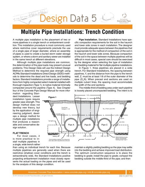
In Figure 1, three pipelines are placed in a wide<br />
trench. For Standard Installations, the spacing between<br />
pipelines, Y, and the distance from the pipe to the trench<br />
wall, Z, must be at least 1/6 of the outer diameter of the<br />
pipe (D o /6). When precast end sections are used on<br />
multiple culvert lines, the spacing must accommodate<br />
the width of the end sections.<br />
The middle-third of bedding area under each pipeline<br />
is loosely placed uncompacted bedding. The intent is to<br />
Do/6 (Min.) Z Y<br />
Y<br />
Do<br />
Do<br />
Outer bedding materials and compaction<br />
each side, same requirements as haunch<br />
<strong>Pipe</strong> A <strong>Pipe</strong> B<br />
<strong>Pipe</strong> C<br />
D o/3<br />
1.8 D o<br />
0.4 Do 0.4 D o<br />
Do<br />
D o/3<br />
H<br />
Foundation<br />
We = Prism Load (VAF)<br />
Do<br />
Do (Min.)<br />
maintain a slightly yielding bedding so the pipe may settle<br />
into the bedding and achieve improved load distribution.<br />
The optimum construction sequence is to place the<br />
bedding to grade; install the pipe to grade; compact the<br />
bedding outside the middle-third of the pipe; and then<br />
<strong>American</strong> <strong>Concrete</strong> <strong>Pipe</strong> <strong>Association</strong> • www.concrete-pipe.org • info@concrete-pipe.org<br />
© 2011 <strong>American</strong> <strong>Concrete</strong> <strong>Pipe</strong> <strong>Association</strong>, all rights reserved.<br />
D o/3<br />
Haunch<br />
Lower Side<br />
Middle Bedding loosely<br />
placed uncompacted<br />
bedding except Type 4<br />
1<br />
DD 5 (07/11)
place and compact the haunch zone up to the springline<br />
of the pipe. To effectively compact the soil in the haunch<br />
zone, it may be necessary to increase the dimensions<br />
of Y and Z beyond D o /6.<br />
Analyze Loading Condition. The selection of pipe<br />
strength by the indirect design method requires six<br />
steps: determine the dead load, determine the live load,<br />
select bedding, determine bedding factors for dead and<br />
live loads, apply the factor of safety, and select the pipe<br />
strength.<br />
Dead Load. For a Standard Installations positive<br />
projecting embankment installation, the dead load supported<br />
by the pipe is the weight of the prism of earth over<br />
the outside diameter of the pipe and increased by the<br />
Table 1<br />
<strong>Pipe</strong> Size D in Inches<br />
B c<br />
(ft.)<br />
Vertical Arching Factor, (VAF).<br />
PL = w H + Do<br />
4 – π<br />
8<br />
Do and Dead Load; We = (VAF) PL<br />
where; PL = prism load (lb./ft.),<br />
w = soil unit weight (lbs./ft. 3 ),<br />
H = height of fill (ft.),<br />
Do = outside diameter (ft.).<br />
The VAF accounts for the additional dead load transferred<br />
to the pipe by settlement of the earth adjacent to<br />
the prism. The representation of the dead load from the<br />
earth prism and the additional effect of the VAF is shown<br />
Height of Fill H Above Top of <strong>Pipe</strong> in Feet<br />
0.5 1.0 1.5 2.0 2.5 3.0 3.5 4.0 5.0 6.0 7.0 8.0 9.0<br />
12 1.33 3780 2080 1470 1080 760 550 450 380 290 230 190 160 130<br />
15 1.63 4240 2360 1740 1280 900 660 540 450 350 280 230 190 160<br />
18 1.92 4110 2610 1970 1460 1030 750 620 520 400 320 260 220 190<br />
21 2.21 3920 2820 2190 1620 1150 840 690 580 450 360 300 250 210<br />
24 2.50 4100 3010 2400 1780 1270 930 760 640 500 400 330 380 240<br />
27 2.79 3880 2940 2590 1930 1380 1010 830 700 560 440 360 300 260<br />
30 3.08 3620 2930 2770 2070 1480 1080 890 750 590 480 390 330 280<br />
33 3.38 3390 2930 2950 2200 1580 1160 960 810 630 510 420 360 300<br />
36 3.67 3190 2810 2930 2330 1670 1230 1020 860 670 550 450 380 330<br />
39 3.96 3010 2670 2850 2440 1760 1290 1070 910 710 580 480 410 350<br />
42 4.25 2860 2550 2770 2560 1840 1360 1130 950 750 610 510 430 370<br />
48 4.83 2590 2330 2620 2480 1990 1470 1230 1040 820 670 560 470 410<br />
54 5.42 2360 2150 2490 2360 2050 1580 1320 1120 890 730 610 520 440<br />
60 6.00 2170 1990 2450 2250 1960 1680 1400 1190 950 780 650 560 480<br />
66 6.58 2010 1850 2520 2160 1880 1640 1480 1260 1010 830 700 590 510<br />
72 7.17 1870 1730 2580 2190 1810 1570 1510 1330 1060 880 740 630 540<br />
78 7.75 1750 1630 2630 2240 1770 1520 1460 1390 1110 920 780 660 570<br />
84 8.33 1650 1540 2730 2290 1810 1460 1410 1360 1160 960 810 690 600<br />
90 8.92 1550 1460 2530 2330 1850 1470 1360 1310 1210 1000 850 720 630<br />
96 9.50 1470 1380 2410 2290 1880 1500 1330 1270 1250 1040 880 750 650<br />
102 10.08 1390 1320 2300 2190 1910 1530 1350 1240 1290 1070 910 780 680<br />
108 10.67 1320 1260 2200 2090 1830 1560 1380 1230 1330 1110 940 810 700<br />
114 11.25 1260 1200 2110 2010 1760 1540 1410 1260 1362 1140 970 830 730<br />
120 11.83 1210 1150 2020 1930 1700 1480 1420 1280 1400 1170 990 860 750<br />
128 12.42 1160 1100 1940 1860 1640 1430 1380 1300 1430 1200 1020 880 770<br />
132 13.00 1110 1060 1870 1800 1580 1380 1330 1290 1460 1220 1040 900 790<br />
138 13.58 1070 1020 1800 1730 1530 1340 1290 1250 1490 1250 1070 920 810<br />
144 14.17 1020 980 1740 1670 1480 1300 1250 1210 1470 1280 1090 940 830<br />
<strong>Data</strong>: 1. Unsurfaced roadway.<br />
2. Loads – AASHTO HS 20, two 16,00 lb. dual-tired wheels, 4 ft. oncenters, or alternate loading, four 12,000 lb. dual-tired<br />
wheels, 4 ft. on centers with impact included.<br />
Notes: 1. Interpolate for intermediate pipe sizes and / or fill heights.<br />
2. Critical loads:<br />
a. For H = 0.5 and 1.0 ft., a single 16,000 lb dual-tired wheel.<br />
b. For H = 1.5 through 4.0 ft., two 16,000 lb. dual-tired wheels, 4 ft. on center.<br />
c. For H > 4.0 ft. alternate loading<br />
3. Truck live load for H = 10.0 ft or more are insignificant.<br />
<strong>American</strong> <strong>Concrete</strong> <strong>Pipe</strong> <strong>Association</strong> • www.concrete-pipe.org • info@concrete-pipe.org<br />
© 2011 <strong>American</strong> <strong>Concrete</strong> <strong>Pipe</strong> <strong>Association</strong>, all rights reserved.<br />
(1)<br />
(2)<br />
2<br />
DD 5 (07/11)
on <strong>Pipe</strong> B in Figure 1. The values for VAF for each type<br />
of bedding are:<br />
• Type 1 VAF = 1.35<br />
• Type 2 VAF = 1.40<br />
• Type 3 VAF = 1.40<br />
• Type 4 VAF = 1.45<br />
Live Load. The live load effect may be a significant<br />
factor in the design of shallow multiple pipelines because<br />
intensity of a live load is highest at the surface. It is distributed<br />
over a larger area as the depth of cover over a<br />
pipeline increases. Loads on pipe from highway,<br />
Figure<br />
Figure<br />
1 Loads<br />
2 Loads<br />
on <strong>Concrete</strong><br />
on <strong>Concrete</strong><br />
<strong>Pipe</strong> Installed<br />
<strong>Pipe</strong> Installed<br />
Under<br />
Under<br />
Railways<br />
Railways<br />
Unit Load On Top of <strong>Pipe</strong>, Pounds Per Square Foot (WL & WD)<br />
3000<br />
2500<br />
2000<br />
1500<br />
1000<br />
500<br />
1.40 x wH<br />
Unfactored<br />
Live Load<br />
Including<br />
Impact<br />
Unit Earth Load*<br />
0<br />
0 2 4 6 8 10 12 14<br />
Height of Cover, H, Above Top of <strong>Pipe</strong>, Feet<br />
and railway loading are found in Table 1 and Figure 2.<br />
The AASHTO LRFD Standard applies a dynamic load<br />
allowance to account for the truck load being non-static.<br />
The dynamic load allowance, IM is determined by Equation<br />
3:<br />
IM =<br />
33(1.0 - 0.125H)<br />
100<br />
Selection of Bedding and Determination of Bedding<br />
Factors. Bedding is provided to distribute the vertical<br />
reaction around the lower exterior surface of the pipe<br />
and to reduce stress concentrations within the pipe wall.<br />
Embankment bedding factors for five common diameters<br />
of pipe are found in Table 2. For sizes not tabulated,<br />
Table 2 Bedding Factors, Embankment<br />
Table 2 Bedding Factors, Embankment<br />
Conditions, B<br />
Conditions, B fe<br />
fe<br />
<strong>Pipe</strong><br />
Standard Installation<br />
Diameter Type 1 Type 2 Type 3 Type 4<br />
12 in. 4.4 3.2 2.5 1.7<br />
24 in. 4.2 3.0 2.4 1.7<br />
36 in. 4.0 2.9 2.3 1.7<br />
72 in. 3.8 2.8 2.2 1.7<br />
144 in. 3.6 2.8 2.2 1.7<br />
Notes: 1. For pipe diameters other than listed in Table 3, embankment<br />
condition factors, Bfe can be obtained by interpolation.<br />
2. Bedding factors are based on the soils being placed with<br />
the minimum compaction specified in Illustrations 4.5 and<br />
4.7 for each standard installation.<br />
the bedding factor for the next larger size may be selected,<br />
or a more exact factor may be interpolated between<br />
the tabulated sizes that bracket the selected size. Live<br />
Load bedding factors are found in Table 3. The live load<br />
factors may be selected by a method similar to that used<br />
Table Table 3 Bedding 3 Bedding Factors, Factors, B B , for HS20<br />
fLL, for fLL HS20<br />
Live Loadings Live Loadings<br />
Fill<br />
Height <strong>Pipe</strong> Diameter, Inches<br />
Ft. 12 24 36 48 60 72 84 96 108 120 144<br />
0.5 2.2 1.7 1.4 1.3 1.3 1.1 1.1 1.1 1.1 1.1 1.1<br />
1.0 2.2 2.2 1.7 1.5 1.4 1.3 1.3 1.3 1.1 1.1 1.1<br />
1.5 2.2 2.2 2.2 2.0 1.8 1.5 1.5 1.4 1.4 1.3 1.3<br />
2.0 2.2 2.2 2.2 2.0 1.8 1.5 1.5 1.4 1.4 1.3 1.3<br />
2.5 2.2 2.2 2.2 2.2 2.0 1.8 1.7 1.5 1.4 1.4 1.3<br />
3.0 2.2 2.2 2.2 2.2 2.2 2.2 1.8 1.7 1.5 1.5 1.4<br />
3.5 2.2 2.2 2.2 2.2 2.2 2.2 1.9 1.8 1.7 1.5 1.4<br />
4.0 2.2 2.2 2.2 2.2 2.2 2.2 2.1 1.9 1.8 1.7 1.5<br />
4.5 2.2 2.2 2.2 2.2 2.2 2.2 2.2 2.0 1.9 1.8 1.7<br />
5.0 2.2 2.2 2.2 2.2 2.2 2.2 2.2 2.2 2.0 1.9 1.8<br />
5.5 2.2 2.2 2.2 2.2 2.2 2.2 2.2 2.2 2.2 2.0 1.9<br />
6.0 2.2 2.2 2.2 2.2 2.2 2.2 2.2 2.2 2.2 2.1 2.0<br />
6.5 2.2 2.2 2.2 2.2 2.2 2.2 2.2 2.2 2.2 2.2 2.2<br />
Notes: 1. For pipe diameters other than listed in Tabel 4,<br />
B fLL values can be obtained by interpolation.<br />
<strong>American</strong> <strong>Concrete</strong> <strong>Pipe</strong> <strong>Association</strong> • www.concrete-pipe.org • info@concrete-pipe.org<br />
© 2011 <strong>American</strong> <strong>Concrete</strong> <strong>Pipe</strong> <strong>Association</strong>, all rights reserved.<br />
(1)<br />
3<br />
DD 5 (07/11)
to find the embankment factors; choose the lower factor<br />
of the two tabulated bracketing sizes, or interpolate for<br />
a more exact value. The bedding factors appear in the<br />
denominator of the pipe strength equation, therefore, a<br />
smaller bedding factor means higher pipe strengths are<br />
required.<br />
Factor of Safety. The Indirect <strong>Design</strong> method is<br />
based on service load conditions. The 0.01-inch crack<br />
width is used as the criterion of service strength of pipes<br />
tested in the three-edge-bearing test. The relationship<br />
of ultimate test strength and the 0.01-inch test strength<br />
criteria is 1.5 for D-loads of 2000 pounds/ft./ft. or less and<br />
1.25 for D-load strengths greater than 3000 pounds/ft./ft.<br />
The ratio of factors is interpolated between 1.5 and 1.25<br />
for D-loads between 2000 and 3000 pounds/ft./ft.A Factor<br />
of Safety of 1.0 shall be applied to the 0.01 inch cracking<br />
strength of the pipe.<br />
Selection of <strong>Pipe</strong> Strength. Since numerous reinforced<br />
concrete pipe sizes are available, three-edgedbearing<br />
(TEB) test strengths are classified by D-loads.<br />
The D-load concept provides strength classification<br />
independent of pipe diameter. For reinforced circular pipe,<br />
the TEB test load in pounds per linear foot equals D-load<br />
Figure Figure 3 3<br />
Do/6 Do/6<br />
Do<br />
<strong>Pipe</strong> A<br />
Do/3<br />
Alternate 2<br />
Outer bedding materials and compaction<br />
each side, same requirements as haunch<br />
H A<br />
Bedding<br />
x inside diameter in feet. For arch, horizontal elliptical,<br />
and vertical elliptical pipe, the TEB test load in pounds<br />
per linear foot equals D-load x nominal inside diameter<br />
in feet. The required TEB test strength for non-reinforced<br />
concrete pipe is expressed in pounds per lineal feet of<br />
pipe. The required TEB strength of a circular reinforced<br />
concrete pipe is expressed as the D-load, and is computed<br />
by:<br />
We D – load = +<br />
Bfe W L<br />
BfLL<br />
F.S.<br />
D<br />
where; We = dead load (lb./ft.)<br />
Bfe = embankment bedding factor,<br />
WL = live load (lb./ft.),<br />
BfLL = live load bedding factor,<br />
F.S. = Factor of Safety,<br />
D = inside diameter.<br />
For arch and elliptical pipe, replace D, the inside diameter,<br />
with S, the inside span. When calculating HS20<br />
highway live loading, if the value of the dead load bedding<br />
factor is smaller than the live load bedding factor,<br />
Alternate 1<br />
Do/6<br />
Do<br />
Bd<br />
<strong>Pipe</strong> B<br />
Do/3<br />
Do/6<br />
HB<br />
Middle Bedding loosely<br />
placed uncompacted<br />
bedding except Type 4<br />
<strong>American</strong> <strong>Concrete</strong> <strong>Pipe</strong> <strong>Association</strong> • www.concrete-pipe.org • info@concrete-pipe.org<br />
© 2011 <strong>American</strong> <strong>Concrete</strong> <strong>Pipe</strong> <strong>Association</strong>, all rights reserved.<br />
(4)<br />
4<br />
DD 5 (07/11)
substitute the lower value for the tabulated live load factor<br />
in the D-load equation.<br />
BENCHED TRENCH<br />
Another common type of multiple pipeline installations<br />
is illustrated in Figure 3, where the pipe is separated<br />
vertically as well as horizontally. Generally, the criteria<br />
established by the local jurisdiction will require minimum<br />
vertical and horizontal separations between the pipelines,<br />
and possibly the minimum dimension of Y in respect to X,<br />
especially if pipe A is a storm sewer and B is a sanitary<br />
sewer, or if there is concern for the stability of the bench<br />
under pipe A.<br />
A benched trench installation includes more complex<br />
design variables to consider than does the flat trench. The<br />
economy of a common excavation, or restricted trench<br />
width, is the principle reason for using the benched trench<br />
installation. Dead Loads on the pipelines may resemble<br />
either a Standard Installations trench or positive projecting<br />
embankment installation. Construction of a benched<br />
installation trench is frequently made in one of two following<br />
sequences;<br />
• For the first method, the lower pipeline is installed<br />
in a conventional trench and the trench is backfilled<br />
and compacted to the foundation elevation<br />
of the upper pipeline. In some cases. A partial<br />
bench may be excavated in the side slope. If any<br />
portion of the pipe installation cross-section of<br />
the upper pipeline is within the side slope of the<br />
trench, the backfill material in the trench must be<br />
uniformly compacted to specified SIDD installation<br />
requirements.<br />
• In the second method, the lower pipeline is installed<br />
in a conventional trench and the trench<br />
is backfilled to the foundation elevation of the<br />
upper pipeline. When the horizontal alignment<br />
of the upper pipeline is entirely outside the side<br />
slope of the trench of the lower pipeline, a bench<br />
is excavated at the foundation elevation of the<br />
upper pipeline.<br />
In moderate trench width conditions, as is typically<br />
found in the lower pipeline, the resulting earth load is<br />
equal to the weight of the soil within the trench minus the<br />
shearing or frictional forces on the sides of the trench.<br />
Since the newly installed backfill material will settle more<br />
than the existing soil on the side of the trench, the friction<br />
along the trench wall will relieve the pipe of some of the<br />
soil burden.<br />
As the trench width increases, the reduction in the<br />
load from frictional forces is offset by the increase in the<br />
soil weight in the trench. As the trench width increases it<br />
starts to behave as an embankment, where the soil on<br />
the side of the pipe settles more than the soil above the<br />
pipe. Eventually, the embankment condition is reached<br />
when the trench walls are too far away from the pipe to<br />
help support the soil immediately adjacent to it. This is<br />
the transition width of the trench, where the trench load<br />
equals the embankment load. Any pipe designed in a<br />
trench width equal to or greater than the transition width<br />
should be designed as an embankment condition.<br />
Analyze Loading Condition. The selection of pipe<br />
strength by the indirect design for a benched trench requires<br />
the same six steps as the flat trench: determine<br />
the dead load, determine the live load, select bedding,<br />
determine bedding factors for dead and live loads, apply<br />
factors of safety, and select pipe strength. For a benched<br />
trench installation, both trench and embankment dead<br />
loads must be compared because for the same depth of<br />
cover, trench dead loads are less, but the bedding factors<br />
are also smaller.<br />
Dead Load. The dead load on the lower pipeline<br />
should be selected as the greater load from either the<br />
SIDD trench or positive projecting embankment condition,<br />
while the dead load on the upper pipeline may be calculated<br />
by SIDD positive projecting embankment methods<br />
as used for flat trenches. For the trench condition:<br />
Wd = w CdB 2<br />
d + Do 2<br />
4 – π<br />
8<br />
– 2Kµ'<br />
and, Cd =<br />
1 – e<br />
2Kµ'<br />
where; W = soil with weight (lbs./ft 3 .)<br />
Bd = width of trench (ft.),<br />
Do = outside diameter (ft.),<br />
K = ratio of active lateral unit<br />
pressure to vertical unit pressure,<br />
µ' = Tan ø, coefficient of friction<br />
between fill material and side<br />
of trench.<br />
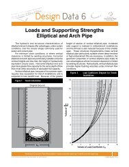
The value of C d may be read directly from Figure 4, Load<br />
Coefficient Diagram For Trench Installations. Typical<br />
values for Kµ’ are:<br />
H<br />
Bd<br />
(5)<br />
(6)<br />
• Kµ' = 0.1924 Max. for granular materials without<br />
cohesion<br />
• Kµ' = 0.165 Max. for sand and gravel<br />
• Kµ' = 0.150 Max. for saturated top soil<br />
• Kµ' = 0.130 Max. for ordinary soil<br />
• Kµ' = 0.110 Max. for saturated clay<br />
Figure 4 = Figure 214, page 403 of the <strong>Design</strong><br />
Manual.<br />
<strong>American</strong> <strong>Concrete</strong> <strong>Pipe</strong> <strong>Association</strong> • www.concrete-pipe.org • info@concrete-pipe.org<br />
© 2011 <strong>American</strong> <strong>Concrete</strong> <strong>Pipe</strong> <strong>Association</strong>, all rights reserved.<br />
5<br />
DD 5 (07/11)
For a Standard Installations positive projecting<br />
embankment condition, the dead load supported by the<br />
pipe is the weight of the prism of earth over the outside<br />
diameter of the pipe and increased by the Vertical Arching<br />
Factor, (VAF).<br />
PL = w H + Do<br />
4 – π<br />
8<br />
D o<br />
and Dead Load; W e = (VAF) PL<br />
where; PL = prism load (lb./ft.),<br />
w = soil unit weight (lbs./ft. 3 ),<br />
H = height of fill (ft.),<br />
D o = outside diameter (ft.).<br />
Live Load. Loads on pipe from highway and railway<br />
loading are found in Table 1 and Figure 2. Impact or<br />
dynamic loads need not be added to highway live loads<br />
for buried concrete pipelines constructed from circular,<br />
elliptical, and arch shaped pipe sections with cover less<br />
than eight feet.<br />
Selection of Bedding and Determination of Bedding<br />
Factors. Most benched trench installations will<br />
have adequate space for compaction of haunch and<br />
sidefill materials, therefore, any of the four Standard<br />
Installations bedding installation types may be used.<br />
Embankment bedding factors for five common diameters<br />
of pipe are found in Table 3. For sizes not tabulated, the<br />
bedding factor for the next larger size may be selected,<br />
or a factor may be interpolated between the tabulated<br />
sizes if a more accurate value is required. Minimum trench<br />
bedding factors for each of the four types of Standard<br />
Installations beddings are found in Table 4. The variable<br />
trench bedding factor may be determined by a series of<br />
interpolations of positive projecting embankment and<br />
trench bedding factors. Live Load bedding factors are<br />
found in Table 3. The live load factors may be selected<br />
by a method similar to that used to find the embankment<br />
factors: choose the lower factor of the two tabulated<br />
sizes, or interpolate for a more exact value.<br />
Table 4 Trench Minimum Bedding Factors, B<br />
Table 4 Trench Minimum Bedding Factors, Bfo<br />
fo<br />
Standard Installation Minimum Bedding Factors, B fo<br />
Type 1 2.3<br />
Type 2 1.9<br />
Type 3 1.7<br />
Type 4 1.5<br />
(1)<br />
(2)<br />
Notes: 1. Bedding factors are based on the soils being placed with the<br />
minimum compaction specified in Illustrations 4.5 and 4.7 for<br />
each Standard Installation.<br />
2. For pipe installed in trenches dug in previously constructed<br />
embankment, the load and the bedding factor should be<br />
determined as an embankment condition unless the backfill<br />
placed over the pipe is of lesser compaction than the embankment.<br />
Factor of Safety. A Factor of Safety of 1.0 shall be<br />
applied to the 0.01 inch cracking strength of the pipe.<br />
Selection of <strong>Pipe</strong> Strength. The required TEB strength<br />
of a circular reinforced concrete<br />
pipe is expressed as the D-load, and is computed by<br />
Equation 4:<br />
We D – load = +<br />
Bfe W L<br />
BfLL<br />
F.S.<br />
D<br />
where; W e = dead load (lb./ft.)<br />
B fe = embankment bedding factor,<br />
W L = live load (lb./ft.),<br />
B fLL = live load bedding factor,<br />
F.S. = Factor of Safety,<br />
D = inside diameter.<br />
For arch and elliptical pipe, replace D, the inside<br />
diameter, with S, the inside span. When applying HS20<br />
highway live loading, if the value of the dead load bedding<br />
factor is smaller than the live load bedding factor,<br />
substitute the lower value for the tabulated live load factor<br />
in the D-load equation.<br />
DESIGN EXAMPLES<br />
Given: A builder is developing a business on an<br />
environmentally sensitive site near a lake. The designer<br />
is required to provide a storm water retention system<br />
that will store the additional runoff due to development,<br />
before it can reach the lake. Because the cost of land is<br />
expensive, and for aesthetic reasons, a buried system<br />
will be used. The natural ground elevation averages ten<br />
feet above ground water.<br />
To avoid the cost of dewatering, the designer has<br />
selected an assembly of parallel rows of 60-inch diameter<br />
B-wall concrete pipe that have an outer diameter of 72<br />
inches installed two feet above the ground water. The<br />
rows of pipe will be connected with special precast 60inch<br />
diameter tees that have an eight-foot laying length.<br />
The native soil where the storm water detention structure<br />
will be constructed is poorly graded sand with a unit<br />
weight of 120 pounds per cubic foot.<br />
Find: The required strength of the 60-inch pipe.<br />
Solution: This is an example of a flat multiple trench<br />
installation.<br />
(4)<br />
1.0 Determine Dead Load. The 60-inch pipeline will<br />
be installed two feet above the water table. The<br />
fill height, H = 10-(2+6)= 2 ft. From Equations (1)<br />
and (2),<br />
<strong>American</strong> <strong>Concrete</strong> <strong>Pipe</strong> <strong>Association</strong> • www.concrete-pipe.org • info@concrete-pipe.org<br />
© 2011 <strong>American</strong> <strong>Concrete</strong> <strong>Pipe</strong> <strong>Association</strong>, all rights reserved.<br />
6<br />
DD 5 (07/11)
PL = 120 2 + 6<br />
4 – π<br />
6 = 1904 lb./ft.<br />
8<br />
For a Type 2 Installation the VAF = 1.40.<br />
DeadLoad, We = 1.4 x 1904 = 2665.6 lb./ft.<br />
2.0 Determine Live Load.<br />
From Table 1, Highway loads on Circular <strong>Pipe</strong>,<br />
for 60-inch diameter pipe and H = 2 ft,<br />
Live Load = 2250 lb./ft.<br />
In this example, a portion of the ground surface<br />
over the pipelines will be a paved parking lot and<br />
the remainder green space. Highway live loads<br />
should be included in both cases, but since loads<br />
will never be severe, the impact factor may be<br />
deleted. Normally, a live load impact factor of<br />
25% is applied to installations with two feet of<br />
cover over the pipeline as shown in Equation 3<br />
of this document.<br />
Live Load (Adjusted), W L = 2250 ÷ 1.25 = 2813<br />
lb./ft.<br />
3.0 Selection of Bedding. Only Type 3 and Type 4<br />
installations are recommended for multiple pipe<br />
installations in restricted areas, because it is<br />
difficult to adequately compact the haunch and<br />
side fill areas. Type 3 bedding instead of Type 4<br />
has been selected for this installation, because<br />
native soils are suitable and a portion of the<br />
surface over the installation will be paved. A Type<br />
4 installation would be adequate if the entire<br />
surface was green space.<br />
4.0 Determine Bedding Factors.<br />
The dead load bedding factors are found in Table<br />
2, Bedding Factors, Embankment Condition. The<br />
60-inch diameter pipe size is not included in the<br />
table. Select the bedding factor of 2.2 for 72-inch,<br />
the next larger size. In this case, because of<br />
the small difference between the factors for the<br />
next smaller size (36 inch) and 72 inch, it is not<br />
beneficial to interpolate for a more exact value.<br />
The live load bedding factor is found in Table 3,<br />
Bedding Factors for HS20 Live Loadings. The<br />
factor for a 60-inch diameter pipe with 2 feet of<br />
fill is 1.8. That value is less than the dead load<br />
factor of 2.2 and may be used without adjustment.<br />
5.0 Apply Factor of Safety.<br />
The factor of safety is 1.0 based on a 0.01 crack<br />
width in a TEB Test.<br />
6.0 Selection of <strong>Pipe</strong> Strength.<br />
The required D-load strength of a pipe is found<br />
by Equation (3).<br />
D – Load= 2665.6 2250 1.0<br />
+<br />
= 492.3lb./ft./ft.<br />
2.2<br />
1.8<br />
For this installation, an ASTM C76 Class I pipe will<br />
be adequate. Many experienced designers will specify<br />
ASTM C76 Class II as a minimum strength if the pipe will<br />
be subjected to any highway live loading.<br />
EXAMPLE 2<br />
Given: The installation of two pipelines in a single<br />
trench beneath a city street is proposed. The lines are a<br />
48-inch storm sewer line and a 30-inch sanitary sewer<br />
with a maximum of one foot between the outside of any<br />
pipe and the adjacent trench wall. The local code states,<br />
“The outside top of the sanitary sewer must be a minimum<br />
of three feet below the outside bottom of the storm<br />
sewer, and the horizontal spacing shall be equal to or<br />
greater than the vertical spacing”. The height of fill over<br />
the 48-inch line is five feet, and 13 feet over the 30-inch<br />
line. The pipes will be installed with a Type 2 bedding and<br />
backfilled with ordinary clay weighing 130 PCF.<br />
Find the required strength of the pipes in D-load:<br />
Since the 48-inch storm sewer pipeline is installed in<br />
a wide and relatively shallow trench, it will be analyzed<br />
as a positive projecting embankment condition.<br />
The 30-inch sanitary sewer pipeline is installed in a<br />
conventional trench, with the pipe centered with a distance<br />
of one foot between the pipe springline and trench<br />
walls. The transition width of the trench must be known<br />
to determine if the largest earth load on the pipe is due<br />
to either a positive projecting embankment, or a trench<br />
condition.<br />
1.0 Determine Dead Loads.<br />
1.1 48-inch storm sewer.<br />
For a fill height, H = 5 ft., VAF=1.4 From Equations<br />
(1) and (2) for a SIDD positive projecting<br />
embankment,<br />
4 – π<br />
PL = 130 5 + 4.83 4.83 = 3465 lb./ft.<br />
8<br />
We = 1.4 (3465) = 4851 lb./ft.<br />
1.2 30-inch sanitary sewer with a fill height, H<br />
= 13 ft.<br />
1.2.1 Using the Transition Width tables, for a 30inch<br />
B-wall pipe installed in ordinary clay, with<br />
13 feet of fill, the transition trench width B dt , is<br />
<strong>American</strong> <strong>Concrete</strong> <strong>Pipe</strong> <strong>Association</strong> • www.concrete-pipe.org • info@concrete-pipe.org<br />
© 2011 <strong>American</strong> <strong>Concrete</strong> <strong>Pipe</strong> <strong>Association</strong>, all rights reserved.<br />
5<br />
7<br />
DD 5 (07/11)
5.8 feet. The trench width, B d , for this example<br />
is found by adding two feet to the outside diameter<br />
of the pipe, or B d , = ((30+(2)x3.5)/12)+2 =<br />
5.1 feet. The trench width, B d , is less than the<br />
transition width, B dt , so using the trench condition<br />
is the appropriate method to determine the<br />
required pipe strength. Equation (5) will be used<br />
to determine the dead load on the pipe. The Load<br />
Coefficient Diagram, Figure 4, will be used to<br />
select C d .<br />
H/B = 13/5.1 = 2.55, and C = 1.85<br />
d d<br />
4 - π<br />
Wd = 130 1.85(5.1)2 + 3.12 = 6390 lb./ft.<br />
8<br />
2.0 Determine Live Load.<br />
2.1 48-inch storm sewer.<br />
From Table 1, Highway loads on Circular <strong>Pipe</strong>,<br />
for 48-inch diameter pipe and H = 5 ft,<br />
Live Load, W L = 820 lb./ft<br />
2.2 30-inch sanitary sewer.<br />
The live load is negligible at a 13-foot depth and<br />
may be ignored for this installation.<br />
Live Load, W L = 0 lb./ft.<br />
3.0 Selection of Bedding.<br />
There is adequate space at the springline of the<br />
lower and upper pipelines for proper compaction<br />
of the haunch and sidefill material. A Type 2<br />
installation with selected imported material was<br />
initially selected, because the native clay material<br />
may be difficult to compact.<br />
If initial calculations indicate relatively low<br />
dead loads on the lower pipeline, a Type 3 installation<br />
should be investigated. An economic<br />
analysis will have to be made to see if the costs<br />
of importing select fill materials, and disposal of<br />
excavated soil, is offset by the increase in cost<br />
for a stronger pipe. The upper pipeline has only<br />
five feet of fill, and its required strength will be<br />
less sensitive to the type of bedding specified,<br />
than will the lower pipeline.<br />
4.0 Determine Bedding Factors.<br />
4.1 48-inch storm sewer.<br />
The dead load bedding factors are found in<br />
Table 2, Bedding Factors, Embankment Condition.<br />
The 48-inch diameter pipe size is not<br />
included on the table. Select the bedding factor<br />
of 2.8 for 72-inch, the next larger size. In this<br />
case, because of the small difference between<br />
the factors for the next smaller size (36 inches)<br />
and 72 inches, it is not beneficial to interpolate<br />
for a more exact value.<br />
The live load bedding factor is found in Table 3,<br />
Bedding Factors for HS20 Live Loadings. The<br />
factor for a 48-inch diameter pipe with 5 feet of<br />
fill is 2.2. That value is less than the dead load<br />
factor of 2.8 and may be used without adjustment.<br />
4.2 30-inch sanitary sewer.<br />
The bedding factors for the positive projecting<br />
embankment and trench installations<br />
must be determined to calculate the variable<br />
bedding factor used for this installation. In Table<br />
2, the positive projecting embankment dead<br />
load factor is 2.9 for a 36-inch diameter pipe in<br />
a Type 2 installation. In this case, because of<br />
the small difference between the factors for the<br />
next smaller size, (24-inches) and 36-inches, it<br />
is not beneficial to interpolate for a more exact<br />
value.The minimum trench bedding factor of 1.9<br />
is found in Table 4.<br />
The Standard Installations variable trench<br />
bedding factor is calculated by adding an increment<br />
of the difference between the trench and<br />
positive projecting embankment load factors, to<br />
the minimum trench load factor.<br />
Δsw<br />
Bfv = Bfo + ΔBf<br />
(7)<br />
Δtw<br />
where; Bfv = variable trench bedding factor<br />
Bfo = minimum trench bedding factor<br />
ΔBf = (Bfe, bedding factor,<br />
embankment) –<br />
(Bfo, minimum trench bedding<br />
factor)<br />
Δsw = (Bd, trench width at top of pipe)–<br />
(Do, outside horiz. span of<br />
pipe, feet)<br />
Δtw = (Bdt, transit. width at top of<br />
pipe, ft.)–<br />
(Do, outside horiz. span of<br />
pipe, ft.)<br />
The variable trench bedding factor from equation<br />
(7) is:<br />
5.1 - 3.1<br />
Bfv = 1.9 + 1.0 = 2.62 (7)<br />
5.9 - 3.1<br />
The live load is negligible at a 13-foot depth and<br />
may be ignored for this installation.<br />
<strong>American</strong> <strong>Concrete</strong> <strong>Pipe</strong> <strong>Association</strong> • www.concrete-pipe.org • info@concrete-pipe.org<br />
© 2011 <strong>American</strong> <strong>Concrete</strong> <strong>Pipe</strong> <strong>Association</strong>, all rights reserved.<br />
8<br />
DD 5 (07/11)
5.0 Apply Factor of Safety.<br />
The factor of safety is 1.0 based on a 0.01 crack<br />
width in a TEB Test.<br />
6.0 Selection of <strong>Pipe</strong> Strength.<br />
6.1 48-eight inch storm sewer.<br />
The required D-load strength of a pipe is found<br />
by Equation (4).<br />
4851 820 1<br />
D-Load = + = 526.3 lb./ft./ft.<br />
2.8 2.2 4<br />
ASTM C-76 Class I<br />
6.2 30-inch sanitary sewer.<br />
The required D-load strength of a pipe is found<br />
by Equation (4).<br />
6390 1<br />
D-Load = - 0 = 975 lb./ft./ft.<br />
2.62 2.5<br />
ASTM C-76 Class III<br />
For this installation, ASTM C76 Class II pipes will<br />
provide adequate strength for both sizes. Since<br />
the cost increment between Class II and Class III<br />
strength tend to be small in these sizes, a Type 3<br />
installation may be practical in spite of the extra<br />
effort required to compact clay material.<br />
<strong>American</strong> <strong>Concrete</strong> <strong>Pipe</strong> <strong>Association</strong> • www.concrete-pipe.org • info@concrete-pipe.org<br />
© 2011 <strong>American</strong> <strong>Concrete</strong> <strong>Pipe</strong> <strong>Association</strong>, all rights reserved.<br />
Technical data herein is considered reliable, but no guarantee is made or liability assumed.<br />
(1)<br />
(1)<br />
9<br />
DD 5 (07/11)