Lewis Gun Mechanism Made Easy.pdf - Forgotten Weapons
Lewis Gun Mechanism Made Easy.pdf - Forgotten Weapons
Lewis Gun Mechanism Made Easy.pdf - Forgotten Weapons
Create successful ePaper yourself
Turn your PDF publications into a flip-book with our unique Google optimized e-Paper software.
BOOKS SPECIALLY RECOMMENDED<br />
Elementary Drill Memory Card for Squad Commanders.<br />
Gives in concise form action to be taken by a Squad Commander<br />
on commands being given by Company or Platoon Commanders.<br />
By Post<br />
CONTENTS.-Formlng Up-Action of Markers-Falling ln-Dresslnc-Squad<br />
Drill Movemenu-When to give words of command.<br />
Drill In Threes and Elementary Drill<br />
By Post<br />
General Instructions for Drilling Recruits-Squad Drill without Arms<br />
Squad Drill with Arms-Platoon and Company Drill.<br />
Reproduced from Training Pamphlet No. 18, and Manual of Elementary Drill<br />
(All Arms). 1935, by permrssion of The Controller of H.M. Stationery Office.<br />
Small Arms Anti-Aircraft Training Arranged by Major T. J.<br />
Edwards, M.B.E., F.R.Hlst.Soc. .. . .. . ... ... ...<br />
By Post<br />
Reproduced from S.A. T., Vol. I, Pamphlet5 Nos. 4, 6 and 20, by permission of the<br />
Controller of H.M. Stationery Office.<br />
The Complete lewis <strong>Gun</strong>ner. A practical sequence of Instruction,<br />
in simple language and as few technicalities as Is compatible<br />
with efficiency. Fully illustrated with plates and diagrams .. .<br />
By Post<br />
lewls <strong>Gun</strong> <strong>Mechanism</strong> <strong>Made</strong> <strong>Easy</strong>. By Major C. H. B. Pridham,<br />
The Duke of Wellington's Regt. (late Officer Instructor, School<br />
of Musketry, Hythe). In handy book form with large folding<br />
Coloured Plate. (Revised to date.) With comparable notes on<br />
the American weapon ... .. . . . . . . . . . . . . . each<br />
By Post<br />
Bren light Machine <strong>Gun</strong>. Folder In cover, of handy pocket size.<br />
Printed in colours ... ... ... . . . ... ... . ..<br />
By Post<br />
The Browning Heavy Machine <strong>Gun</strong> <strong>Mechanism</strong> <strong>Made</strong> <strong>Easy</strong><br />
(.300 Calibre Model 1917, Water Cooled) ... ... ... . ..<br />
By Post<br />
The <strong>Mechanism</strong> of the Browning Automatic Rifle In pocket<br />
form. Illustrated with plates and diagrams.<br />
By Post<br />
*Vickers Machine <strong>Gun</strong> <strong>Mechanism</strong> <strong>Made</strong> <strong>Easy</strong>. Fully illustrated<br />
with half-tone plates .. . .. . . . . . . . .. . ...<br />
By post<br />
* This book Is applicable to both the English and American Vickers <strong>Gun</strong>.<br />
lantern Slides for lecture Purposes. Lantern slides In Black<br />
and White cif any of the illustrations in this book can be supplied<br />
at 2s. 6d. each. These slides are invaluable for indoor lecturing<br />
purposes.<br />
Log Book and History Sheet for Automatic <strong>Weapons</strong>. Size,<br />
11•x 6•, In bag container to keep the book clean ... ... each<br />
per doz.<br />
Extra History Sheets, per doz.<br />
VIsual Training and Application of Fire ...<br />
Reproduad from Small Arms Training, Vol. 1, 1937, by permission By Post<br />
of The Controller of H.M . Stationery Office.<br />
s. d.<br />
0 6<br />
0 7<br />
3<br />
6<br />
3<br />
6<br />
2 0<br />
2 3<br />
6<br />
8<br />
0<br />
I<br />
6<br />
8<br />
0<br />
I<br />
6<br />
8<br />
0 9<br />
8 0<br />
3 0<br />
0 9<br />
0 11<br />
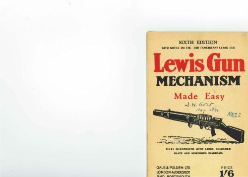
LEWIS GUN MECHANISM<br />
MADE EASY<br />
By<br />
MAJOR C. H. B. PRIDHAM<br />
The Duke of Wellington's Regiment<br />
(Late Officer-Instructor, School of Musketry, Hythe)<br />
SIXTH EDITION<br />
WITH NOTES ON<br />
THE .300 (AMERICAN) LEWIS GUN<br />
ALDERSHOT<br />
GALE & POLDEN LTD.
:P-8510<br />
First Published J anuaTy, 1919<br />
Fifth Edition July, 1940<br />
Sireth Edition November, Hl40<br />
Eighteenth Impression March, 1941<br />
PRINTJm DY GllE & POLDEN LTD.,<br />
WELLINGTON WORKS, ALDERSHOT<br />
1941<br />
PREFACE TO REVISED EDITION<br />
(NOVEMBER, 1940)<br />
RAPID TRAINING<br />
THis handbook for <strong>Lewis</strong> <strong>Gun</strong>ners (1st Edition in 1919)<br />
was the first of its kind to supplement the old official<br />
textbooks, which were not specially adapted for rapid<br />
training purposes.<br />
Method of arrangement (Text and Diagrams) is<br />
intended:<br />
(a) To Save Time in Training.<br />
(b) To arouse interest in the gunner, with a view<br />
to increasing his skill in rapidly applying<br />
accurate bursts of fire on to any target.<br />
Text has been set out to catch the eye.<br />
The intricate design of the mechanism is thus made<br />
clear to the understanding of any sailor, soldier,<br />
airman-gunner, or A.A. gunner of the Mercantile<br />
l\Iarine or Mine-Sweeping Flotillas, Auxiliary Military<br />
Pioneer Corps, and The Home Guard, whose time<br />
available for <strong>Lewis</strong> <strong>Gun</strong> training is limited by his other<br />
numerous duties.<br />
Care of Arms.-Experience in action shows the<br />
great importance of this old subject. A thorough<br />
knowledge of mechanism, particularly fascinating in<br />
the case of the <strong>Lewis</strong> <strong>Gun</strong>, ensures this.<br />
Cooling System.-A unique feature is the Cooling of<br />
the Barrel (see page 10 and Fig. Ill), the most effective<br />
system of Air Cooling ever invented.<br />
This enables the <strong>Lewis</strong> <strong>Gun</strong> to fire, at a rate of 10<br />
rounds per second, for a prolonged period.<br />
No Barrel Changing is necessary.<br />
Diagrams (at end of book) can be spread out and<br />
examined whilst reading the text.<br />
IMPORTANT. - Faulty (foreign manufactured)<br />
ammunition has, in the past, been the main cause of<br />
STOPPAGES. Proper care of the <strong>Gun</strong> (see pages 12<br />
and 13) and use of good ammunition (of British make)<br />
reduce Stoppages to a minimum.<br />
C. H. B. PRIDHAM (Major).
DESCRIPTION OF GUN<br />
LOADING OF GUN<br />
UNLOADING GUN<br />
CONTENTS<br />
ACTION OF MECHANISM IN DETAIL--<br />
DURING TilE BACKWARD l\lOVEMKNT<br />
DURING TilE FORWARD 1\fOVEMENT ..•<br />
I\1ECHANISM OF l\IAGAZINE AND FUNCTIONS OF PARTS<br />
ACTION OF GASES AND COOLING SYSTEM<br />
POINTS TO BE CARRIED OUT BEFORE, DURING, AND AFTER<br />
FIRL'IG<br />
NOTES O N STOPPAGES<br />
htMEDIATE AcTION<br />
TABLE OF STOPPAGES (SECTION "A")<br />
TABLE OF STOPPAGES (SECTION "B ")<br />
Fws. I, II AND Ill (CoLOURED PLATE OF LEwrs GuN)<br />
FIGS. IV, V AND VA (FEED ARM AND PAWLS)<br />
FIGs. VI AND VII (EJECTOR AJ."'D STRIKER PosT)<br />
FIG. VIII (MAGAZINE)<br />
PAGE<br />
2<br />
3<br />
4<br />
7<br />
9<br />
10<br />
12<br />
14<br />
16<br />
19<br />
20<br />
···r At<br />
··· end<br />
... of<br />
Book<br />
LEWIS GUN<br />
MADE<br />
I<br />
MECHANISM<br />
EASY<br />
"THE .303 (and the .300 American type) Light Description<br />
Automatic <strong>Gun</strong>-Air cooled-Gas operated- of GUN.<br />
Magazine fed."<br />
Weight of <strong>Gun</strong>: 26 to 28 lbs.; Weight of<br />
Mounting, 2£ lbs.<br />
Weight of Magazine: Empty, It lbs.; full<br />
4l lbs. (Holds 47 rounds.)*<br />
Length of <strong>Gun</strong> : 50! inches.<br />
Length of Barrel : 26l inches.<br />
Initial Velocity of Bullet : 2,440 feet per<br />
second.<br />
Two forces work the <strong>Gun</strong> automatically, viz. :<br />
1. The pressure of the Gases, caused by explosion<br />
of the Charge.<br />
2. The Return Spring, contained in the Pinion.<br />
These two forces alone enable the <strong>Gun</strong> to flre<br />
at an average rate of ten rounds per second.<br />
A trained <strong>Lewis</strong> <strong>Gun</strong>ner should be able to fue<br />
with accuracy 150 rounds per minute.<br />
The Position of the Cocking Handle normally<br />
shows whether the <strong>Gun</strong> is " Safe " or Loadedi.e.,<br />
when a Filled Magazine is in position on the<br />
<strong>Gun</strong>:-<br />
A. When C.H. is fully forward (vide Fig. II)<br />
-<strong>Gun</strong> is " Safe."<br />
• NoTE.-Magazines (double-sized, holding about 94.<br />
rounds) are also in use by the Royal Navy<br />
and the R.A.F.
Backward<br />
Movement<br />
(continued)<br />
FEED ARM<br />
PAWL.<br />
MAGAZINE.<br />
(<strong>Mechanism</strong>,<br />
vide<br />
Fig. VIII.)<br />
LIVE<br />
ROUND.<br />
No. 2<br />
(RIGHT)<br />
STOP<br />
PAWL.<br />
No. 2<br />
(LEFT)<br />
STOP<br />
PAWL.<br />
6<br />
carries the Feed Arm across to the Left (vide<br />
Fig. IV).<br />
The Feed Arm Pawl (33), being engaged behind<br />
a Projection (34) on the Magazine, and being<br />
carried across with the Feed Arm, thus rotates<br />
the Magazine one space to the Left.<br />
In the Magazine a Live Round is forced down<br />
the Slope of the Centre Block until the Bullet<br />
end is clear of the Lip, when it drops on to the<br />
Body and into the Cartridge Opening in the<br />
Feed Arm, being assisted down by the Projecting<br />
Tongue (35) of the Body Cover.<br />
The Round is carried to the Left (and forced<br />
into position under the Cartridge Guide) by the<br />
Indentations (36) and Separating Pegs (37) in<br />
the Magazine, assisted by the Right Side of<br />
the Cartridge Opening in the Feed Arm.<br />
The Feed Arm Pawl Spring Retaining Stud (38),<br />
moving to the Left across the Face of the No. 2<br />
(Right) Stop Pawl (39), allows the latter to come<br />
forward [under the influence of the Stop Pawl<br />
Spring (40)] and engage in front of a Projection<br />
(41) on the Magazine, thus preventing the Magazine<br />
from rotating too far in the feeding direction.<br />
The No. 1 (Left) Stop Pawl (42) is pressed back<br />
as a Projection on the Magazine rides over it, but<br />
it cumes forward again when the Projection is<br />
clear and engages behind it, thus preventing the<br />
Magazine from counter rotating.<br />
FEED ARM At the end of the Backward Movement the<br />
TAIL STUD. Feed Arm Actuating Stud disengages from the<br />
7<br />
Grooved Tail of the Feed Arm, which is held in<br />
position ready for the next Forward Movement<br />
by the Positioning Stud on the tail of the Feed<br />
Arm engaging with the Left Side of the Top<br />
Locking Lug on the Bolt.<br />
V<br />
ACTION of MECHANISM during FORWARD<br />
MOVEMENT.<br />
[For Position of <strong>Mechanism</strong> at commencement of<br />
Forward Movement, see Fig. 1.]<br />
When the <strong>Gun</strong> is Cocked the Return Spring is<br />
held compressed by the Nose (19) of the Sear (20),<br />
being engaged in the Bent (18) in rear of the Rack<br />
on the Piston Rod.<br />
On pressing the Trigger, the Nose of the Sear<br />
is released from the Bent, and the Return Spring<br />
(10) comes into play and rotates the Pinion (9).<br />
The Teeth of the Pinion being engaged with<br />
the Teeth on the Rack (8), the Piston Rod (7) is<br />
driven forward.<br />
The Striker Post (11 ), being now held in the<br />
Rear end of the Cam Slot (13) in the Bolt (14),<br />
tries to rotate the Bolt, but cannot, owing to the<br />
Lugs (15}, which are prevented from turning in<br />
the Guide Grooves (17).<br />
The Bolt is therefore carried forward by the<br />
Striker Post.<br />
Forward<br />
Movement.<br />
Action of-<br />
SEAR and<br />
BENT.<br />
PINION and<br />
RETURN<br />
SPRING.<br />
STRIKER<br />
POST and<br />
BOLT.<br />
The Feed Arm Actuating Stud (30) is also car- F.A.A.S. and<br />
ried forward with the Bolt, and, riding inside the FEED ARM.<br />
Grooved Tail (31) of the Feed Arm, carries the<br />
Feed Arm (32) over to the Right (vide Fig. V).
Forward<br />
Movement<br />
(continued)<br />
FEED ARM<br />
PAWL<br />
No. 2<br />
(RIGHT)<br />
STOP<br />
PAWL<br />
No. 1<br />
(LEFT)<br />
STOP<br />
PAWL<br />
TOP<br />
EXTRACTOR<br />
CARTRIDGE<br />
GUIDE,<br />
CARTRIDGE<br />
.and BULLET<br />
STOPS.<br />
8<br />
The Feed Arm Pawl (33) during this movement<br />
passes over a projection on the Magazine, and<br />
engages behind it.<br />
The Feed Arm Pawl Spring Retaining Stud (38)<br />
on the Feed Arm, moving to the Right, presses<br />
back the No. 2 (Right) Stop Pawl (39) out of the<br />
way of the Magazine.<br />
The No. 1 (Left) Stop Pawl (42) remains<br />
stationary, preventing the Magazine from rebounding<br />
or being drawn back by the Feed Arm<br />
Pawl.<br />
During the Forward Movement of the Bolt the<br />
Top Extractor (43) meets the Rim of the Cartridge,<br />
and pushes it forwards and downwards, into the<br />
Chamber, the Cartridge being guided and controlled<br />
during this movement by the Cartridge<br />
Guide (44), Cartridge (45) and Bullet Stops (46)<br />
on the Feed Arm and the Shoulders of the<br />
Cartridge Slot in the Body.<br />
BOLT. The face of the Bolt knocks the Head of the<br />
Ejector (29) out of the Boltway, and the Tail (27)<br />
swings in behind ready for the Backward Movement.<br />
EXTRACTORS. The Extractors spring over the Rim of the<br />
Cartridge as it goes into the Chamber.<br />
STRIKER<br />
POST.<br />
The Bolt is now forward to the full extent;<br />
the Lugs (15) are clear of the Guide Grooves and<br />
opposite the Locking Recesses (16) in the Body.<br />
The Striker Post (11) is now able to rotate the<br />
Bolt to the Right, and the Lugs enter the Locking<br />
Recesses (16), thus locking the Bolt.<br />
i<br />
9<br />
The Striker Post meanwhile has pushed its<br />
way through the Curved Portion (13) of the Cam<br />
Slot, and it now enters the straight portion.<br />
The Striker (47) travels along the straight<br />
portion, its nose passes through the Striker Way<br />
in the face of the Bolt, hits the Cap, and explodes<br />
the Charge.<br />
VI<br />
MECHANISM of the MAGAZINE and Functions<br />
of PARTS.<br />
I.-The MAGAZINE consists of:<br />
(A) Circular Rotating Pan, and<br />
(B) Inner Ring.<br />
These are riveted together and rotate arow1d<br />
(C) The Centre Block of Aluminium, and<br />
(D) The Centre Disc with Catch and Spring.<br />
These are also riveted together, but remain<br />
stationary.<br />
H.-When the MAGAZINE is not in use :-<br />
1. Nib on the end of the Catch is engaged in<br />
one of the twenty-five recesses of the Inner Ring,<br />
which also carries the Separating Pegs.<br />
2. This prevents the Pan from rotating arow1d<br />
the Centre Block, except when a loading Handle<br />
has been inserted into the Central Opening or<br />
Axis Hole for the purpose of Filling.<br />
Forward<br />
Movement<br />
(continued)<br />
STRIKER.<br />
See Fig. VIII<br />
Diagrams<br />
1 to 7.<br />
MAGAZINE<br />
off the GUN.<br />
IlL-When a Filled MAGAZINE is fixed on the MAGAZINE<br />
GUN :- on the GUN.<br />
l. Magazine Catch is forced to the Right by<br />
the Hollow Cone of the Magazine Post ; this disengages<br />
the Nib from the Recess on the Inner<br />
Ring, and frees the Pan from the Centre Disc.
STOPPAGES.<br />
TEMPORARY<br />
STOPPAGES.<br />
PROLONGED<br />
STOPPAGES.<br />
POSITION<br />
of C.H.<br />
14<br />
X<br />
NOTES on STOPPAGES.<br />
1. In common with other Automatic <strong>Gun</strong>s, the<br />
<strong>Lewis</strong> <strong>Gun</strong> is liable to Accidental Cessation of<br />
Fire or Stoppages.<br />
The object of the <strong>Lewis</strong> <strong>Gun</strong>ner is to get the<br />
<strong>Gun</strong> firing again in the shortest possible time.<br />
2. Roughly, about 90 per cent. of p.ll Stoppages<br />
can be rectified at once by the application of what<br />
is known as " Immediate Action." Others can be<br />
remedied quickly by Examination of the <strong>Gun</strong>, a<br />
thorough knowledge of <strong>Mechanism</strong>, and practice<br />
in rectifying Stoppages.<br />
3. STOPPAGES may be either TEMPORARY<br />
or PROLONGED.<br />
(1) Temporary: Those which can be cured<br />
by Immediate Action; these are<br />
generally due to neglect of the Points<br />
to be observed Before, During or After<br />
Firing.<br />
(2) Prolonged: These involving stripping<br />
down the <strong>Gun</strong> to remove a jamb<br />
caused by Breakage, or to rectify<br />
any failure in the <strong>Mechanism</strong> which<br />
cannot usually be carried out under<br />
Fire, and which put the <strong>Gun</strong> out of<br />
Action for a more or less prolonged<br />
period.<br />
4. In any STOPPAGE the COCKING HANDLE<br />
stops in one of two different POSITIONS, known<br />
as:lst<br />
Position<br />
2nd Position<br />
C.H. is fully forward.<br />
C.H. in any po!>ition<br />
between 1st (as above)<br />
and <strong>Gun</strong> fully cocked.<br />
15<br />
Knowledge of the Causes of Stoppage peculiar<br />
to each position, and how to rectify them in the<br />
shortest possible time, is essential.<br />
N.B.-These Positions can be quickly determined<br />
by TOUCH, as follows :-<br />
With Butt in Shoulder, raise Fingers (extended)<br />
of Right Hand straight up from the Pistol Grip.<br />
If C.H. is felt at the Tips of the Fingers-<br />
1st Position.<br />
If C.H. is felt on any other part of the Hand-<br />
2nd Position.<br />
5. When STRIPPING a GUN to clear a STOP<br />
PAGE, take care not to alter the Tension on the<br />
Return Spring. Whenever possible, see that<br />
C.H. is forward before removing or replacing<br />
Pistol Grip.<br />
Correct way to remove the Bolt.-Take off Butt<br />
-Hold up Pinion with Left Hand-Disengage<br />
Pistol Grip--Drop Pinion-Pull out Piston Rod.<br />
Caution.-Bolt will not go into Boltway if<br />
(1) Tail of Ejector protrudes into Boltway.<br />
(2) Rear End of Bolt is not properly screwed<br />
up.<br />
6. To remove a Separated Case from the<br />
Chamber, use of the Clearing Plug is necessary, as<br />
follows:-<br />
To remove Separated Case:-<br />
(1) Insert tapered end of Clearing Plug into<br />
Chamber, with centre pin pushed back.<br />
(2) Press Trigger, allowing Bolt to force<br />
centre pin forward.<br />
(3) Give Clearing Plug Handle an up-anddown<br />
rocking motion.<br />
POSITION<br />
FOUND BY<br />
TOUCH.<br />
NOTE ON<br />
STRIPPING.<br />
HOW TO<br />
USE<br />
CLEARING<br />
PLUG.
Fig. I<br />
shows LEWIS GUN loaded and ready to FIRE.<br />
Cocking Handle is in Rear Position. Live<br />
Round is held in position under Cartridge Guide<br />
(44), resting on shoulders of Carh·idge Slot in the<br />
Body. Return Spring (10) is held compressed<br />
owing to Nose of Sear being engaged in Bent<br />
behind Rack of Piston Rod.<br />
Fig. 11<br />
shows position of MECHANISM the moment after<br />
STRIKER (47) has exploded CHARGE.<br />
Cocking Handle is in Forward Position. Bullet<br />
(1) has been forced down Barrel by the pressure<br />
of the Gases. Breech is locked to take the force<br />
of the explosion.<br />
Fig. Ill<br />
shows the BACKWARD MOVEMENT of the<br />
MECHANISM in progress, and Action of the<br />
GASES operating the COOLING SYSTEM.<br />
Bullet has left the Muzzle. A portion of the Gases<br />
has entered the Gas Vent (2), passed through<br />
Gas Chamber (3), and into Gas Cylinder (5), thus<br />
forcing Piston Rod (7) to the Rear. This action<br />
has unlocked the Breech, and is winding up<br />
Return Spring. The Bolt, moving to the Rear,<br />
has extracted the Empty Case (23), which is about<br />
to be ejected through Ejection Slot.<br />
INDEX TO PLATES<br />
1. Bullet (ii).<br />
2. Gas Vent (iil.<br />
3. Gas Chamber (ii).<br />
4 . Gas Regulator (ii).<br />
5. Gas Cylinder (ii).<br />
6. Head of the Piston Rod (ii).<br />
7. Piston Rod (i).<br />
8. Teeth on the Hack (i), (ii).<br />
9. Teeth on the Pinion (i).<br />
10. Retum Spring (i).<br />
11. Striker Post (i).<br />
12. Cam Slot (i).<br />
l 3. Curved Portion of Cam Slot (i) .<br />
l 4. Bolt (i).<br />
l5. Locking Lugs (i) .<br />
l6. Locking Recesses (i).<br />
17. Guide Grooves (i).<br />
LB. Bent (i).<br />
19. Nose of the Sear (ii).<br />
20. Sear (i).<br />
21. Trigger Spring (i).<br />
22. Extmctors (iii).<br />
23. Empty Case (iii).<br />
24. Chamber (i).<br />
25. Left Lug (vi).<br />
26. R ear End of the Bolt (i), (vi).<br />
27. 'fail of the E jector (iil, (vi).<br />
28. Ejector (vi).<br />
29. H ead of the E jector (i), (v i).<br />
30. Feed Arm Actuating Stud (i), (iv), ( v),<br />
(vi).<br />
31. Grooved Tail (i), (iv), (v).<br />
32. Feed Arm (i).<br />
33. Feed Arm Pawl (iv), (v), (va).<br />
34. Projection (iv), (v).<br />
35. Projecting Tongue (i), (ivJ.<br />
36. Indentations (iv), (v).<br />
37. Separating Pegs (iv).<br />
38. Feed Arm Pawl Spring Reta ining Stud<br />
(iv), (v), (va).<br />
39. No. 2 (Right) Stop Pawl (iv), (v).<br />
40. Stop Pawl Spring (iv), (v).<br />
41. Projection (iv), (v).<br />
42. No. 1 (Left) Stop Pawl (iv), (v).<br />
43. Top Extractor (ii), (v).<br />
44. Cartridge Guide (i), (iv).<br />
45. Cartridge Stop (iv), (va).<br />
46. Build Stop (iv), (va).<br />
47. Striker (ii).<br />
4-8. Barrel Mouthpiece (iii).<br />
49. Fore Radiator Casing (iii).<br />
50. Flanges of the Radiator (iii).<br />
N.B.- Roman numerals ·refer to the Diruuoms
No. 3 . No. 5.<br />
No. 4.<br />
No. 6.<br />
No. 7.<br />
FIG. VIII (See Pages 9 and 10).<br />
Diagram 1 showing (A) Magazine Pan.<br />
Diagram 2 showing (B) Inner Ring, with 25 Separating<br />
Pegs and Recesses.*<br />
Diagram 3 showing the Pan and Ring riveLed toget her,<br />
showing how Round is held in position by Rim Plates<br />
and Separating Pegs.<br />
Diagram 4 show ing (C) Centre Block of Alutnin ium,<br />
showing Spiral Channel, Ramp, and Lip Jor Bullet end<br />
of round ; also Key Way and Central Opening.<br />
Diagram 5 showing (D) Centre Disc, Catch, a nd Spring.<br />
D iagram (j showing Centre Disc- top view. Note portion<br />
painted White.<br />
Diagram 7 showing Magazine with Centre Disc removed.<br />
*N.B.-Double-sized Magazines are also in use. tSee page 1.)


