Jabiru UL 450 - the Light Aircraft Association
Jabiru UL 450 - the Light Aircraft Association
Jabiru UL 450 - the Light Aircraft Association

You also want an ePaper? Increase the reach of your titles
YUMPU automatically turns print PDFs into web optimized ePapers that Google loves.
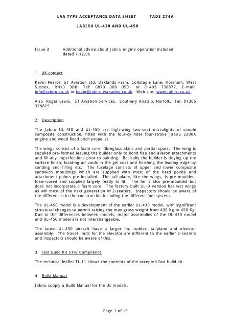
LAA TYPE ACCEPTANCE DATA SHEET TADS 274A<br />
JABIRU <strong>UL</strong>-430 AND <strong>UL</strong>-<strong>450</strong><br />
Issue 3 Additional advice about <strong>Jabiru</strong> engine operation included<br />
dated 7.12.06<br />
1. UK contact<br />
Kevin Pearce, ST Aviation Ltd, Oaklands Farm, Coltstaple Lane, Horsham, West<br />
Sussex, RH13 9BB. Tel: 0870 300 0501 or 01403 738877. E-mail:<br />
info@jabiru.co.uk or kevin@jabiru.wanadoo.co.uk. Web site: www.jabiru.co.uk.<br />
Also Roger Lewis. ST Aviation Services. Sou<strong>the</strong>ry Airstrip, Norfolk. Tel: 01366<br />
378829.<br />
2. Description<br />
The <strong>Jabiru</strong> <strong>UL</strong>-430 and <strong>UL</strong>-<strong>450</strong> are high-wing two-seat microlights of simple<br />
composite construction, fitted with <strong>the</strong> four-cylinder four-stroke <strong>Jabiru</strong> 2200A<br />
engine and wood fixed pitch propeller.<br />
The wings consist of a foam core, fibreglass skins and partial spars. The wing is<br />
supplied pre-formed leaving <strong>the</strong> builder only to bond flap and aileron attachments<br />
and fill any imperfections prior to painting. Basically <strong>the</strong> builder is tidying up <strong>the</strong><br />
surface finish, locating air voids in <strong>the</strong> gel coat and finishing <strong>the</strong> leading edge by<br />
sanding and filling etc. The fuselage consists of upper and lower composite<br />
sandwich mouldings which are supplied with most of <strong>the</strong> hard points and<br />
attachment points pre-installed. The tail plane, like <strong>the</strong> wings, is pre-moulded,<br />
foam-cored and supplied largely ready to fit. The fin is also pre-moulded but<br />
does not incorporate a foam core. The factory-built <strong>UL</strong>-D version has wet wings<br />
as will most of <strong>the</strong> next generation of 2-seaters. Inspectors should be aware of<br />
<strong>the</strong> differences in <strong>the</strong> construction including <strong>the</strong> different fuel system.<br />
The <strong>UL</strong>-<strong>450</strong> model is a development of <strong>the</strong> earlier <strong>UL</strong>-430 model, with significant<br />
structural changes to permit raising <strong>the</strong> max gross weight from 430 Kg to <strong>450</strong> Kg.<br />
Due to <strong>the</strong> differences between models, major assemblies of <strong>the</strong> <strong>UL</strong>-430 model<br />
and <strong>UL</strong>-<strong>450</strong> model are not interchangeable.<br />
The latest <strong>UL</strong>-<strong>450</strong> aircraft have a larger fin, rudder, tailplane and elevator<br />
assembly. The travel limits for <strong>the</strong> elevator are different to <strong>the</strong> earlier 2-seaters<br />
and inspectors should be aware of this.<br />
3. Fast Build Kit 51% Compliance<br />
The technical leaflet TL.11 shows <strong>the</strong> contents of <strong>the</strong> accepted fast build kit.<br />
4. Build Manual<br />
<strong>Jabiru</strong> supply a Build Manual for <strong>the</strong> <strong>UL</strong> models.<br />
Page 1 of 19
5. Build Inspections<br />
LAA TYPE ACCEPTANCE DATA SHEET TADS 274A<br />
JABIRU <strong>UL</strong>-430 AND <strong>UL</strong>-<strong>450</strong><br />
Build inspection schedule 35 (<strong>Jabiru</strong> two-seat aircraft).<br />
Inspector approval codes A-A or A-C or A-C1. Inspector signing off final<br />
inspection also requires ‘first flight’ endorsement<br />
6. Maintenance Manual<br />
<strong>Jabiru</strong> supply an Operators Manual for <strong>the</strong> <strong>UL</strong> models which contains a<br />
maintenance schedule.<br />
7. Flight Manual<br />
<strong>Jabiru</strong> supply a Pilot’s Manual for <strong>the</strong> <strong>UL</strong> models. Note that information contained<br />
in <strong>the</strong> pilot’s manual is not always consistent with LAA data (eg max gross<br />
weight, cg limits and engine max rpm). Where a conflict exists, LAA Permit to Fly<br />
data takes precedence over <strong>Jabiru</strong> Pilot’s Manual information.<br />
8. Mandatory Permit Directives<br />
Several MPDs apply to <strong>the</strong> two seat <strong>Jabiru</strong>s, as follows:<br />
MPD: 2006-001 Mandatory Installation of Fuel Header Tank. Only applies to<br />
models with fuel tanks in wings, in which case to avoid engine power loss a fuel<br />
system header tank must be installed. Required no later than 5 February 2006.<br />
MPD: 2006-002 Inboard Lower Seat Belt Attachments. In <strong>the</strong> event of an<br />
accident, to avoid injury to occupants where aircraft seat belts use <strong>the</strong> same<br />
attachment point as <strong>the</strong> main undercarriage, <strong>the</strong> aircraft must be modified within<br />
20 hours or <strong>the</strong> first Permit renewal after 9 January 06. <strong>Jabiru</strong> Service Bulletin<br />
STSB-001 applies.<br />
MPD: 1998-019-R1 Flexible Fuel Tubing. This MPD applies to all Permit aircraft<br />
with flexible fuel tubing on a repetitive annual basis.<br />
9. LAA Mandatory Modifications<br />
As shown below, not all modifications for two-seat <strong>Jabiru</strong>s apply to <strong>the</strong> <strong>UL</strong>-430<br />
and <strong>UL</strong>-<strong>450</strong> model but all are described here for information purposes.<br />
MOD-274-001 Aileron control stops, oversized to stop <strong>the</strong> possibility of control overriding<br />
<strong>the</strong> stops. Part No. STA/001.<br />
MOD-274-002 Hole in firewall for noseleg steering rod requires elongating to provide<br />
sufficient clearance.<br />
MOD-274-003 Drain holes to rear fuselage. Cockpit and ventral fin.<br />
MOD-274-004 Stop added to prevent parking brake cam rotating over <strong>the</strong> top of its arc<br />
and inadvertently applying parking brake.<br />
MOD-274-005 Fuel filler cap central bolt peened over after assembly.<br />
MOD-274-006 All exposed foam sealed with two coats of epoxy.<br />
MOD-274-007 Magneto clear plastic guard fitted between switches (not applicable to wide<br />
instrument panel option).<br />
Page 2 of 19
LAA TYPE ACCEPTANCE DATA SHEET TADS 274A<br />
JABIRU <strong>UL</strong>-430 AND <strong>UL</strong>-<strong>450</strong><br />
MOD-274-008 Reinforcement of wing carry through. (Applicable to <strong>UL</strong>-430 and SP-430<br />
models only).<br />
MOD-274-009 Sponge protection to carry through angle (Applicable to <strong>UL</strong>-430 and SP-430<br />
models only).<br />
MOD-274-010 Front cowling retainers (bent aluminium) that are riveted to <strong>the</strong> lower<br />
cowling and protrude into a slot cut into <strong>the</strong> top cowling. The top cowling<br />
requires flexing to remove and protects against forgotten catches. Now<br />
incorporated in kit.<br />
MOD-274-011 Addition of extractor lip to lower cowling (not required if optional oil cooler<br />
fitted)<br />
MOD-274-012 Mandatory Inspection of rod end bearings.<br />
MOD-274-013 Mandatory Wing disbond check.<br />
MOD-274-014 Flap deflection increased to 37 degrees in order to meet microlight stall<br />
speed limit (applicable to <strong>UL</strong>-430 and <strong>UL</strong>-<strong>450</strong> models only). Optional<br />
change to flap gate to restore flaps retracted position to zero deflection.<br />
All of <strong>the</strong> above modifications are classified A - mandatory, except MOD-274-011,<br />
which is classified B – recommended.<br />
10. Service Bulletins<br />
The following service bulletins have been raised by <strong>Jabiru</strong>, or STA. Note this does<br />
not include bulletins relating to <strong>the</strong> <strong>Jabiru</strong> engine, only <strong>the</strong> airframe. For engine<br />
bulletins consult STA website.<br />
SB No. Subject<br />
UKJSB001 Rod End Bearings (Compulsory immediately)<br />
UKJSB002 Choke & Carb Heat Cable (Compulsory)<br />
JSP-04 Inspection & Repair of skin to core wing disbonds<br />
STSB-001 Seat Belt inner attachment (Compulsory within 20 flying<br />
hours)<br />
JSB 009 Belville washers on prop bolts (Recommended)<br />
STSB-002 Minimum Fuel Wet Wings (Compulsory immediately)<br />
JSL-003-1 Fuel Tank Sealant (Advisory)<br />
11. Standard Options<br />
Oil cooler (recommended)<br />
Cabin Heat<br />
Instrument panel cold air vents<br />
Ice Eliminator<br />
Door Locks<br />
NACA intakes for cold and hot air intakes<br />
Replacement of push on oil cooler hoses with threaded Aeroquip stainless braded<br />
hoses<br />
Strobes (Wing tip or Top / Bottom fuselage or Fin mounted<br />
Fixed Hub Caps instead of spats<br />
Wing Folding kit<br />
Page 3 of 19
LAA TYPE ACCEPTANCE DATA SHEET TADS 274A<br />
JABIRU <strong>UL</strong>-430 AND <strong>UL</strong>-<strong>450</strong><br />
12. Special Inspection Points (Refer also to Appendix A of this TADS for fur<strong>the</strong>r<br />
inspection advice)<br />
• The latest <strong>UL</strong>-<strong>450</strong> have a larger fin, rudder, tailplane and elevator assembly.<br />
The travel limits for <strong>the</strong> elevator are different to <strong>the</strong> earlier 2-seaters and<br />
inspectors should be aware of this.<br />
• Examples of <strong>the</strong> factory-built <strong>Jabiru</strong> <strong>UL</strong>-D microlight are emerging onto <strong>the</strong><br />
LAA market and <strong>the</strong>se are under LAA administration. However, <strong>the</strong>se aircraft<br />
are not covered by <strong>the</strong> normal LAA inspector approval and inspectors wishing<br />
to be approved to sign out factory-built <strong>Jabiru</strong>s must first contact LAA<br />
Engineering.<br />
• Peel ply is factory fitted on <strong>the</strong> wing skin at each flap hinge and aileron hinge<br />
attachment. It is essential that this peel ply is removed by <strong>the</strong> builder to<br />
expose a good surface for bonding, to ensure good adhesion when <strong>the</strong> builder<br />
fits <strong>the</strong>se components. The red peel ply may be hidden by <strong>the</strong> white gel coat,<br />
so it is imperative that <strong>the</strong> builder locates and removes <strong>the</strong> peel ply just prior<br />
to bonding items such as flap arms and aileron reinforcements. One builder<br />
omitted to remove <strong>the</strong> peel ply before bonding flap and aileron attachments,<br />
fortunately this potentially disastrous mistake was picked up by inspection<br />
prior to painting.<br />
• Aileron cable attach point inside <strong>the</strong> wing may require moving if correct<br />
aileron throws cannot be attained. (STA have a loan right angle drill if<br />
required).<br />
• The important skin disbond check must be undertaken on all new aircraft and<br />
at permit renewal time. Due to <strong>the</strong> sandwich construction technique<br />
employed by <strong>Jabiru</strong>, it is possible that <strong>the</strong> bond between <strong>the</strong> skin and <strong>the</strong><br />
foam core does not have 100% coverage, leading to voids between <strong>the</strong> skin<br />
and foam core. It is possible that delamination may also occur in service. LAA<br />
MOD-274-013 describes <strong>the</strong> required disbond inspections both at build (prior<br />
to painting) and at annual check. If <strong>the</strong> initial disbond check is done prior to<br />
painting, a torch can be used to illuminate <strong>the</strong> glass and will show all glue<br />
lines and <strong>the</strong>refore missing glue lines. Some voidage is permitted in certain<br />
low-stress areas, defined by <strong>Jabiru</strong>. Take care to distinguish between<br />
defective bonding and areas where <strong>the</strong> underlying foam is cut away to<br />
accommodate control runs etc. If voids are suspected, check with ST before<br />
proceeding with any repair action.<br />
• The build manual calls for five staggered layers of glass that stiffen <strong>the</strong> joint<br />
between <strong>the</strong> fin and horizontal tail. This lay-up is essential to <strong>the</strong> strength of<br />
<strong>the</strong> fin. We have seen one <strong>Jabiru</strong> presented with reinforcement missing. In<br />
ano<strong>the</strong>r case, <strong>the</strong> builder used <strong>the</strong>se lay-ups to encapsulate a VHF aerial, <strong>the</strong>n<br />
later <strong>the</strong> reinforcement was cut through to remove <strong>the</strong> aerial and no action<br />
taken to make good <strong>the</strong> severed plies. O<strong>the</strong>r areas where vital layers of glass<br />
are added are tailplane to fuselage, flap horns to wing. These reinforcements<br />
are essential!<br />
• A common mistake is to place unnecessary washers under heads of bolts that<br />
in turn do not leave enough thread protruding through <strong>the</strong> nut. In particular,<br />
check rudder pedals, rudder control horn, control column, and flap pivot bolts<br />
for this hazardous feature.<br />
Page 4 of 19
LAA TYPE ACCEPTANCE DATA SHEET TADS 274A<br />
JABIRU <strong>UL</strong>-430 AND <strong>UL</strong>-<strong>450</strong><br />
• Fixed elevator tabs, as moulded into kit-supplied elevator must always be<br />
used as <strong>the</strong>y apply positive control loads to <strong>the</strong> elevator control circuit and<br />
augment <strong>the</strong> pitch stability of <strong>the</strong> aeroplane. However <strong>the</strong>y should be reduced<br />
in chord by 10-12mm. This will allow <strong>the</strong> aircraft to trim out to a straight and<br />
level cruise between 94-105 knots. Leaving <strong>the</strong> tabs full width can result in<br />
unwanted pitch-up during test flying.<br />
• Several problems have cropped up with <strong>the</strong> installation of rod end bearings in<br />
<strong>the</strong> control system. Freedom of rotation is sometimes lacking if small steel<br />
spacers are not fitted as per <strong>the</strong> manual drawings. Oversize ¼” washers are<br />
used to prevent connection coming adrift in case of housing failure.<br />
• Male threaded rod ends are screwed into aluminium push rods that are drilled<br />
with a thread inspection hole. Sometimes a burr on <strong>the</strong> thread can make<br />
screwing in <strong>the</strong> rod end difficult – some builders have forced <strong>the</strong> rod end by<br />
placing a bolt or drill through <strong>the</strong> ball and turning. This caused <strong>the</strong> soft metal<br />
outer bearing housing to become deformed and seize, which in turn applied<br />
bending stresses on <strong>the</strong> 3/16” thread which in one case failed after an<br />
estimated 2800 cycles. The correct procedure would have been to carefully<br />
use a tap to clear <strong>the</strong> thread.<br />
• All rod ends should be checked for freedom of rotation and thread security. It<br />
is common to find rod end locking nuts incorrectly installed only finger tight.<br />
• Inclusion of <strong>the</strong> wing tip drain hole is commonly forgotten, but make sure that<br />
<strong>the</strong> ventral fin and cockpit drain holes are also not forgotten or blocked with<br />
debris.<br />
• A common problem is over torquing of <strong>the</strong> propeller bolts, this can cause<br />
cracking in <strong>the</strong> varnish and wood and can cause <strong>the</strong> propeller to quickly crack<br />
fur<strong>the</strong>r and become unserviceable.<br />
• <strong>Jabiru</strong> propellers suffer with leading edge abrasion in <strong>the</strong> root area and<br />
require regular varnish touch up here. If a tip comes into contact with<br />
anything e.g. soft ploughed earth or long grass, use a bright light or sun to<br />
look for small chord-wise cracks in <strong>the</strong> glass skin. Any delamination however<br />
minor must be treated seriously as cases have occurred where <strong>the</strong> entire<br />
glass cloth covering has been shed in flight, having originated from a small<br />
area of delamination.<br />
• It is common for <strong>the</strong> attach / pivot bolt of <strong>the</strong> Flap Actuating Handle to not be<br />
tightened sufficiently, this can lead to <strong>the</strong> flap disengaging on approach with<br />
potentially serious consequences if not caught quickly by <strong>the</strong> pilot.<br />
• It is common for unwanted stiction to develop in <strong>the</strong> elevator control due to<br />
<strong>the</strong> nylon block at <strong>the</strong> rear of <strong>the</strong> push-pull cable failing to slide freely over<br />
<strong>the</strong> aluminium rod. This can lead to notchy control feel and cause overcontrol<br />
problems on takeoff and landing. ST Aviation recommend use of a<br />
silicon-based lubricant here. The wrong type of lubricant can swell <strong>the</strong> nylon<br />
block and increase friction.<br />
Page 5 of 19
LAA TYPE ACCEPTANCE DATA SHEET TADS 274A<br />
JABIRU <strong>UL</strong>-430 AND <strong>UL</strong>-<strong>450</strong><br />
• Care must also be taken to avoid undue friction in <strong>the</strong> rudder control system,<br />
which can lead to failure of <strong>the</strong> rudder controls to self-centre in flight. The<br />
throttle control cable must also be routed with smooth curves to avoid undue<br />
friction or notchiness in <strong>the</strong> throttle control system.<br />
• Great care must be taken to keep <strong>the</strong> weight down on <strong>the</strong>se aircraft especially<br />
for microlight models, which are subject to strict maximum empty weight<br />
limits (268 Kg for <strong>UL</strong>-<strong>450</strong>, 248 Kg for Ul-430).<br />
• The <strong>Jabiru</strong> models also have a ra<strong>the</strong>r narrow cg range and care must be taken<br />
to produce a satisfactory empty cg position if <strong>the</strong> loaded cg is to fit within <strong>the</strong><br />
limits. Particularly with an extensive instrument panel it is often found<br />
necessary to fit a small amount of tail ballast in <strong>the</strong> ventral fin to bring <strong>the</strong><br />
empty cg back to an acceptable location.<br />
• For permit renewal inspections, all normal practices apply and in addition to<br />
<strong>the</strong> <strong>Jabiru</strong> maintenance schedule, owners and inspectors should pay particular<br />
attention to <strong>the</strong> following items.<br />
Rod end bearings – free rotation and no bent threads.<br />
Check main undercarriage legs by getting someone to lift <strong>the</strong> wingtip and<br />
check for fore / aft movement. If movement is found, this is probably<br />
because attachment bolts have become loose due to <strong>the</strong> gear ‘bedding in’. Be<br />
careful that bolts have not become thread-bound, use additional washers if<br />
necessary.<br />
Lift nose and check noseleg for shimmy and up / down movement.<br />
Check noseleg housing for tightness of bolts, cracks or whiteness associated<br />
with stressing.<br />
Check flap arms and all piano hinges for security and play.<br />
Visual disbond check (see MOD-274-013).<br />
Paint chips should be touched up.<br />
Propeller leading edge varnish abrasion, cracks in varnish or wood.<br />
Wheels for dents, cracks and hardware security.<br />
Brake pad adjustment and wear.<br />
Lower flaps and check play, excessive indicates loose rod end bearing bolt,<br />
usually at flap handle.<br />
Check that drain holes are not blocked with debris.<br />
Elevator travel in particular down elevator travel (<strong>Jabiru</strong> bulletin refers).<br />
As aircraft are getting older, play is being found in <strong>the</strong> strut attachment points<br />
due to <strong>the</strong> bush being loose or <strong>the</strong> holes being enlarged. Contact ST Aviation<br />
for repair advice.<br />
Page 6 of 19
LAA TYPE ACCEPTANCE DATA SHEET TADS 274A<br />
JABIRU <strong>UL</strong>-430 AND <strong>UL</strong>-<strong>450</strong><br />
13. Operating Limitations and Placards<br />
Maximum number of occupants authorised to be carried: Two<br />
The aircraft must be operated in compliance with <strong>the</strong> following operating limitations,<br />
which shall be displayed in <strong>the</strong> cockpit by means of placards or instrument<br />
markings:<br />
Aerobatic Limitations<br />
The aeroplane is permitted to fly only for non-aerobatic operation. In this context<br />
non-aerobatic operation includes: i) Any manoeuvre necessary for normal flying<br />
ii) Intentional stalls from level flight<br />
iii) Steep turns in which <strong>the</strong> angle of bank doesn’t exceed 60 degrees<br />
Intentional spinning is prohibited<br />
Loading Limitations<br />
Maximum Total weight Authorised: <strong>UL</strong>-430 : 430 Kg <strong>UL</strong>-<strong>450</strong>: <strong>450</strong> Kg<br />
CG Range: kit serial numbers 477 and above: 1601 mm to 1695 mm aft of<br />
datum.<br />
kit serial numbers below 477: 1601 mm to 1682mm aft of datum<br />
Datum Point is: 1403 mm forward of leading edge of <strong>the</strong> wing.<br />
Engine Limitations<br />
Maximum Engine RPM: 3300<br />
Airspeed Limitations<br />
Maximum Indicated Airspeed: 116 kts<br />
Maximum indicated airspeed with flaps deployed: 70 kts<br />
O<strong>the</strong>r Limitations<br />
The aircraft shall be flown by day and under Visual Flight Rules only.<br />
Smoking in <strong>the</strong> aircraft is prohibited.<br />
Additional Placard<br />
“Occupant Warning - This <strong>Aircraft</strong> has not been Certificated to an International<br />
Requirement”<br />
Fireproof identification plate must be fitted to fuselage, engraved or stamped with<br />
aircraft’s registration letters.<br />
As a microlight aircraft, additional microlight weight placard must be fitted as<br />
described in TL2.11 regarding empty weight and payload.<br />
14. Additional Engine Limitations/Placards<br />
With <strong>Jabiru</strong> 2200A: Max CHT: 210C<br />
Oil temp: 50-110C<br />
Oil pressure 125-525 kPa @3100 RPM<br />
15. Maximum Permitted Empty Weight<br />
Model Engine Max empty weight<br />
<strong>UL</strong>-430 <strong>Jabiru</strong> 2200A 248 Kg<br />
<strong>UL</strong>-<strong>450</strong> <strong>Jabiru</strong> 2200A 268 Kg<br />
Page 7 of 19
LAA TYPE ACCEPTANCE DATA SHEET TADS 274A<br />
16. Special Test Flying Issues<br />
JABIRU <strong>UL</strong>-430 AND <strong>UL</strong>-<strong>450</strong><br />
• Pilots involved in flight testing <strong>Jabiru</strong>s are strongly advised to read Appendix A<br />
of this TADS as this contains important advice relevant to flight testing.<br />
• Fixed elevator tabs, as moulded into kit-supplied elevator must always be<br />
used as <strong>the</strong>y apply positive control loads to <strong>the</strong> elevator control circuit and<br />
augment <strong>the</strong> pitch stability of <strong>the</strong> aeroplane. However <strong>the</strong>y should be reduced<br />
in chord by 10-12mm. This will allow <strong>the</strong> aircraft to trim out to a straight and<br />
level cruise between 94-105 knots. Leaving <strong>the</strong> tabs full width can result in<br />
unwanted pitch-up during test flying.<br />
• Propeller types in common use include <strong>Jabiru</strong> 60” x 40”, GT 151 x 105, GT 151 x<br />
107, Kremen 151 x 14 degrees propellers. Due to improvements in engine<br />
power output during <strong>the</strong> development of <strong>the</strong> <strong>Jabiru</strong> engine, propellers matching<br />
early type engines may not suit later models, or vice-versa.<br />
• With <strong>Jabiru</strong> engine It is imperative that <strong>the</strong> cylinder head bolts and tappets<br />
are checked at 5, 10, 15 and 20 hours. Omitting this check can lead to head<br />
leaks and damage at around 25-50 hours. Have a good look around <strong>the</strong><br />
rocker boxes and make sure oil is present and that <strong>the</strong>re are no signs of<br />
overheating in <strong>the</strong> form of burnt lacquered oil. New engines with hydraulic<br />
tappets need only to have <strong>the</strong> head bolts checked.<br />
• With <strong>Jabiru</strong> engine, encourage test pilot to work <strong>the</strong> engine quite hard to<br />
avoid glazed piston bores, vary rpm settings and do not fly at low power<br />
settings for too long.<br />
17. Control surface deflections<br />
Ailerons Up: TBD<br />
Down: TBD<br />
Elevators Up: TBD<br />
Down: TBD<br />
Rudder Left TBD<br />
Right TBD<br />
Flap Down TBD<br />
Elevator tab Fixed<br />
18. Noise Certification<br />
As a microlight aircraft, a noise certificate must be issued by <strong>the</strong> CAA specific to<br />
each individual aircraft built. A new noise certificate must be obtained following<br />
any change in noise output, including change to engine type, propeller type,<br />
propeller diameter and pitch, type of exhaust, exhaust after-muffler or intake<br />
silencer.<br />
Approved:<br />
F.R.Donaldson<br />
Chief Engineer<br />
---------------- END --------------<br />
Page 8 of 19
LAA TYPE ACCEPTANCE DATA SHEET TADS 274A<br />
JABIRU <strong>UL</strong>-430 AND <strong>UL</strong>-<strong>450</strong><br />
APPENDIX A OF TADS 274A Re: <strong>Jabiru</strong> Airworthiness<br />
The following advice was issued by LAA to <strong>Jabiru</strong> owners in April of 2004, and is<br />
reproduced here in full for information purposes as most still remains pertinent.<br />
As <strong>the</strong> numbers of <strong>Jabiru</strong> aircraft and engines in <strong>the</strong> UK have grown, inevitably<br />
<strong>the</strong>re have been some accidents with <strong>the</strong> type and indeed <strong>the</strong> <strong>Jabiru</strong> has recently<br />
come to feature in <strong>the</strong> AAIB’s accident reports more frequently than we would<br />
like. A number have been ei<strong>the</strong>r damaged or written off (happily without serious<br />
injury) and one or two common features have begun to emerge which clearly<br />
warranted closer attention. With this in mind, and with a number of LAA’ers<br />
itching to get cracking on building <strong>the</strong> as-yet unapproved four seat J400 <strong>Jabiru</strong>, I<br />
decided to accept an invitation from <strong>Jabiru</strong> and <strong>the</strong>ir UK agents ST Aviation to<br />
visit <strong>the</strong> <strong>Jabiru</strong> works at Bundaberg in February of this year to explore <strong>the</strong>se<br />
issues. During <strong>the</strong> week-long trip to Australia I spent several days in meetings<br />
with designer Rod Stiff, certification engineer Alan Kerr, and MD Phil Ainsworth,<br />
visiting <strong>the</strong> several different manufacturing facilities and having an opportunity to<br />
fly <strong>the</strong> J400 as well as <strong>the</strong> latest development of <strong>the</strong> two-seat <strong>UL</strong> model.<br />
This note is a report on <strong>the</strong> findings of <strong>the</strong> trip and contains guidance which I<br />
hope will allow you to get <strong>the</strong> best from your <strong>Jabiru</strong>, operate it safely and avoid<br />
unplanned cost and down-time through accident repairs.<br />
Avoiding Nose Leg Collapses<br />
The <strong>Jabiru</strong> is of course equipped with a conventional nosewheel type<br />
undercarriage, bolted to <strong>the</strong> front of <strong>the</strong> firewall, with trailing-link suspension<br />
using rubber blocks in compression as <strong>the</strong> spring element. Several accidents<br />
have occurred with <strong>the</strong> noselegs of <strong>Jabiru</strong>s collapsing on landing, <strong>the</strong> worst<br />
scenario being a touchdown at too high a speed and too flat an attitude leading to<br />
a bounce, and a subsequent arrival slightly nosewheel-first. While <strong>the</strong> noseleg<br />
has been designed to comply with <strong>the</strong> rigorous Section S noseleg strength<br />
requirements, and shown to meet <strong>the</strong>m by practical test, when abused in this<br />
way it is common for <strong>the</strong> noseleg attachment to break away from <strong>the</strong> firewall and<br />
allow <strong>the</strong> noseleg to fold back. This type of accident is common to o<strong>the</strong>r types of<br />
aircraft, including <strong>the</strong> Cessna 152 – noselegs are intended to support <strong>the</strong> nose of<br />
an aircraft while taxiing and to withstand a moderate impact but not to accept <strong>the</strong><br />
whole weight of an aircraft in a nosewheel-first arrival.<br />
As with all o<strong>the</strong>r nosewheel equipped aircraft, <strong>the</strong> <strong>Jabiru</strong> should always be landed<br />
with <strong>the</strong> stick well back, at close to <strong>the</strong> stall speed, giving initial ground contact<br />
on <strong>the</strong> mainwheels only, <strong>the</strong> nosewheel being gently lowered to <strong>the</strong> ground as<br />
speed decays. Landing <strong>the</strong> aircraft ‘flat’ on all three wheels toge<strong>the</strong>r puts higher<br />
loads on <strong>the</strong> noseleg and invites a bounce or wheelbarrowing. And most<br />
importantly of all, if you should find yourself in a bounce, you should ei<strong>the</strong>r keep<br />
that stick back to hold a slightly nose-high attitude and wait for <strong>the</strong> next<br />
touchdown or, if it is a high bounce, open up <strong>the</strong> power and go round again.<br />
Never check forward on <strong>the</strong> stick during a bounce, as to do so is almost certainly<br />
going to mean a nosewheel-first arrival.<br />
A related issue here is <strong>the</strong> single very short central control column which <strong>the</strong><br />
<strong>Jabiru</strong> is fitted with. This feature makes it impossible for a pilot undergoing a<br />
Page 9 of 19
LAA TYPE ACCEPTANCE DATA SHEET TADS 274A<br />
JABIRU <strong>UL</strong>-430 AND <strong>UL</strong>-<strong>450</strong><br />
conversion to type to have his instructor ‘follow through’ on <strong>the</strong> controls, which<br />
while of little consequence at o<strong>the</strong>r times can be critically important during <strong>the</strong><br />
last few seconds of a landing approach or in dealing with a landing which is going<br />
wrong. One or two noseleg failures and propstrikes have occurred during<br />
conversion flying, <strong>the</strong> instructor being helpless to avoid <strong>the</strong> situation developing.<br />
We now recommend that when carrying out conversion flying, a short temporary<br />
control column extension is fitted which allows <strong>the</strong> instructor to take control more<br />
easily if needs be.<br />
Ano<strong>the</strong>r operational issue is to take care when taxiing over ridges or rough<br />
ground, runway edges etc, to avoid excessively loading <strong>the</strong> noseleg. Such ground<br />
features, if <strong>the</strong>y cannot be avoided, should be approached at slow speed and at<br />
an angle (ie not perpendicular ‘head on’) to allow <strong>the</strong> nosewheel to ride over<br />
<strong>the</strong>m more easily. The <strong>Jabiru</strong> is not suitable for operating from fields as rough as<br />
slower-speed microlights with bigger wheels might use.<br />
The attachment of <strong>the</strong> steel tube noseleg to <strong>the</strong> fuselage firewall is via a<br />
fiberglass moulded bracket attached at its periphery by several small bolts. This<br />
is intended to carry <strong>the</strong> normal landing loads with ease but to allow <strong>the</strong> whole<br />
assembly to break away in a heavy landing without doing major damage to <strong>the</strong><br />
fuselage or firewall, thus limiting <strong>the</strong> extent of <strong>the</strong> required repairs. Experience is<br />
showing however that at best this also results in a broken propeller and shock<br />
loaded engine, but when <strong>the</strong> noseleg breaks free on soft ground <strong>the</strong>re is a risk of<br />
<strong>the</strong> base of <strong>the</strong> firewall digging into <strong>the</strong> earth ra<strong>the</strong>r than skidding over it and<br />
consequently <strong>the</strong> aeroplane may end up on its back. This is very alarming and<br />
potentially dangerous for <strong>the</strong> crew, and also, in turning over, major damage can<br />
be done to <strong>the</strong> wings, struts and wing attachments. We feel that it would be<br />
preferable to carry out even a major repair to <strong>the</strong> firewall than risk a turn-over<br />
accident, and conclude that for <strong>the</strong> UK climate at least, a stronger noseleg<br />
attachment which stands more chance of survival will be preferable in safety<br />
terms to <strong>Jabiru</strong>’s current break-free arrangement. <strong>Jabiru</strong> have <strong>the</strong>refore agreed to<br />
<strong>the</strong> idea of reinforcing <strong>the</strong> attachment of <strong>the</strong> noseleg to <strong>the</strong> fuselage, and are<br />
currently designing a suitable stronger bracket for <strong>the</strong> four seat J400 model which<br />
<strong>the</strong>y intend will be equally applicable to <strong>the</strong> two-seater models. We are also able<br />
to supply details of a simply-fitted modification number 10451 (see enclosed<br />
sketch) which adds an additional support to <strong>the</strong> noseleg and increases <strong>the</strong><br />
strength of <strong>the</strong> attachment, for very little weight penalty. We recommend owners<br />
incorporate this modification on <strong>the</strong>ir aircraft particularly if you operate (or intend<br />
to operate) from a rough strip. For full details of <strong>the</strong> mod, contact LAA<br />
Engineering. It is also recommended that owners keep an eye on <strong>the</strong> moulded<br />
fiberglass flange around <strong>the</strong> perimeter of <strong>the</strong> fiberglass noseleg bracket, to check<br />
whe<strong>the</strong>r <strong>the</strong>re are any signs of <strong>the</strong> flange progressively delaminating in <strong>the</strong><br />
vicinity of <strong>the</strong> bolt holes, suggesting that <strong>the</strong> bolt heads might be close to <strong>the</strong><br />
point of pulling through. Progressive delamination is shown up by local whitening<br />
of <strong>the</strong> fiberglass moulding.<br />
The trailing link noseleg suspension has also been under development recently,<br />
<strong>the</strong> tubular steel rod on which <strong>the</strong> rubber suspension bushes are threaded being<br />
replaced with a solid steel version following problems with <strong>the</strong> tubular version<br />
buckling when overloaded in a heavy landing. Buckling of <strong>the</strong> tube (exaggerated<br />
by a ‘falling rate’ action caused by <strong>the</strong> trailing link geometry) can result in <strong>the</strong><br />
trailing link ‘kneeling down’ to <strong>the</strong> point where <strong>the</strong> base of <strong>the</strong> noseleg may strike<br />
<strong>the</strong> ground, causing a ‘sudden stop’ and fur<strong>the</strong>r noseleg attachment damage. The<br />
uprated parts are available from ST Aviation. Ano<strong>the</strong>r indicator of noseleg<br />
overload having taken place is cracking of <strong>the</strong> paint on <strong>the</strong> steel lugs on <strong>the</strong><br />
Page 10 of 19
LAA TYPE ACCEPTANCE DATA SHEET TADS 274A<br />
JABIRU <strong>UL</strong>-430 AND <strong>UL</strong>-<strong>450</strong><br />
noseleg which mount <strong>the</strong> suspension unit, caused by <strong>the</strong> lugs having distorted<br />
under extreme load.<br />
Avoiding Main Undercarriage Collapses<br />
The <strong>Jabiru</strong> is fitted with separate port and starboard cantilever spring legs, of<br />
fiberglass construction, each attached to strong points in <strong>the</strong> fuselage via one<br />
inboard bolt and two outboard bolts, all bolts being of AN5 size ie 5/16” diameter.<br />
There have been a number of occurrences of main undercarriage collapse due to<br />
<strong>the</strong> rear outboard bolts breaking, allowing <strong>the</strong> leg to fold forward. While in one<br />
case <strong>the</strong> AAIB found during <strong>the</strong> accident investigation that <strong>the</strong> bolts used were of<br />
doubtful quality (defective heat-treatment and evidence of having been re-plated<br />
over old defects suggesting <strong>the</strong>y were ‘bogus parts’), <strong>the</strong> root cause of<br />
undercarriage bolt failures is almost certainly that <strong>the</strong> bolts have become loose in<br />
service, allowing <strong>the</strong> legs to graunch about under load and this in turn applies<br />
excessive bending loads to <strong>the</strong> bolts. It is essential that <strong>the</strong>se undercarriage<br />
attachment bolts are kept properly torqued up so that no relative movement<br />
takes place between <strong>the</strong> legs and <strong>the</strong>ir mountings. It is normal for <strong>the</strong> bolts on a<br />
newly-finished <strong>Jabiru</strong> to loosen a little as <strong>the</strong> clamped-up assembly beds in after a<br />
few landings, so <strong>the</strong> gear legs should be checked for signs of looseness during <strong>the</strong><br />
initial flight testing, and from time to time during subsequent pre-flight checks.<br />
The tightness of <strong>the</strong> undercarriage can be checked by having someone lift each<br />
wing tip in turn to raise a wheel off <strong>the</strong> ground, while ano<strong>the</strong>r pushes backwards<br />
and forwards on <strong>the</strong> raised wheel. You will not be able to detect any movement<br />
with <strong>the</strong> wheel on <strong>the</strong> ground because <strong>the</strong> forward sweep on <strong>the</strong> legs means that<br />
<strong>the</strong> wheel will always be pressing hard against <strong>the</strong> forward limit of any ‘free<br />
play’.<br />
Due to variations in <strong>the</strong> thickness of <strong>the</strong> fuselage lay-up in <strong>the</strong> area of <strong>the</strong> main<br />
gear attachments, problems are sometimes experienced with <strong>the</strong> main leg<br />
attachment bolts being of <strong>the</strong> wrong length for <strong>the</strong> job. The shank length of each<br />
of <strong>the</strong> bolts should be checked before installation and changed if necessary for<br />
new bolts of proper length to match your installation. It is particularly important<br />
that <strong>the</strong> bolts are not too long, resulting in <strong>the</strong> nuts bottoming out on <strong>the</strong> end of<br />
<strong>the</strong> thread (‘threadbound’) ra<strong>the</strong>r than clamping up on <strong>the</strong> leg. Not only does this<br />
leave <strong>the</strong> leg loose, <strong>the</strong> damage done to <strong>the</strong> bolt by <strong>the</strong> cutting action of <strong>the</strong> nut<br />
may precipitate bolt failure from that point. Check <strong>the</strong> number of threads visible<br />
on <strong>the</strong> bolt outside of <strong>the</strong> nut – one and a half to three threads is good, if more<br />
than four threads are visible <strong>the</strong>n <strong>the</strong> nut is most likely threadbound. You can<br />
cure this ei<strong>the</strong>r by fitting a shorter bolt or fitting washers under <strong>the</strong> nut. If <strong>the</strong><br />
aeroplane has been flying with <strong>the</strong> bolts loose or threadbound, or both, <strong>the</strong>n you<br />
would be best advised to change <strong>the</strong> bolts anyway incase <strong>the</strong>y have been<br />
damaged.<br />
The rear pair of bolts are much more highly loaded than <strong>the</strong> front pair, due to <strong>the</strong><br />
geometry of <strong>the</strong> forward-swept legs, and of <strong>the</strong> three it is <strong>the</strong> rear bolts which<br />
have always failed. <strong>Jabiru</strong> have been loath to fit stronger bolts here in <strong>the</strong> past<br />
because <strong>the</strong>y felt that in a crash landing it would be better for <strong>the</strong> bolts to break<br />
cleanly than for <strong>the</strong> bolts to tear <strong>the</strong> fiberglass bottom out of <strong>the</strong> fuselage,<br />
making a much bigger repair scheme necessary. They have agreed however that<br />
such a repair would be quite localized and not particularly difficult nor would it<br />
have any serious safety implications, and so with <strong>Jabiru</strong>’s somewhat reluctant<br />
blessing we have cleared a modification (number 10818 - copy available from LAA<br />
Engineering) which replaces <strong>the</strong> rear pair of AN5 bolts by stronger AN6 bolts. In<br />
Page 11 of 19
LAA TYPE ACCEPTANCE DATA SHEET TADS 274A<br />
JABIRU <strong>UL</strong>-430 AND <strong>UL</strong>-<strong>450</strong><br />
addition to making frequent checks on <strong>the</strong>ir undercarriage attachments for any<br />
signs of looseness developing, we recommend owners fit this modification<br />
especially if <strong>the</strong>y fly from a rough strip.<br />
Directional Control Problems<br />
Accidents have occurred with pilots of <strong>Jabiru</strong> aircraft having trouble coping with<br />
crosswinds, especially when flying from narrow strips. The rudder fitted to <strong>the</strong><br />
<strong>Jabiru</strong> originally only occupied <strong>the</strong> bottom half of <strong>the</strong> height of <strong>the</strong> fin, which gives<br />
perfectly adequate control in normal use (including spin recovery), and crosswind<br />
landings have been demonstrated successfully with this rudder configuration,<br />
using <strong>the</strong> recommended ‘wing down technique’. This does require use of <strong>the</strong> full<br />
rudder deflection however and it can be alarming to find you have full control<br />
applied in <strong>the</strong> flare and nothing ‘in hand’ (under foot ?) for eventualities. Some<br />
owners have ended up in <strong>the</strong> boondocks after <strong>the</strong> <strong>Jabiru</strong> got away from <strong>the</strong>m<br />
directionally on landing. The long-wing <strong>UL</strong> model needs particular care because of<br />
its responsiveness to gusts and <strong>the</strong> relatively small size of <strong>the</strong> ailerons compared<br />
to <strong>the</strong> wingspan (brought about by <strong>the</strong> need for <strong>the</strong> flaps to be as long as possible<br />
to get <strong>the</strong> stall speed down to <strong>the</strong> microlight limit) which results in a slower roll<br />
response, and adverse yaw, not helped by a ponderous rudder response. Some<br />
time ago <strong>Jabiru</strong> introduced an alternative tall rudder of almost twice <strong>the</strong> area<br />
which occupies <strong>the</strong> whole height of <strong>the</strong> fin, and is applicable to all three two-seat<br />
variants. The modification (LAA Mod number 10958), is easily incorporated at<br />
build or retro-fitted on an existing aircraft, using a kit of parts available from ST<br />
Aviation. The new rudder provides significantly greater rudder control authority<br />
which makes cross wind landings more comfortable, and we recommend that<br />
owners of <strong>the</strong> <strong>UL</strong> model in particular install this modification at <strong>the</strong> earliest<br />
convenience. This ‘series’ modification can be installed in accordance with <strong>the</strong><br />
mod sheet without reference to LAA Engineering. On completion your LAA<br />
inspector must inspect <strong>the</strong> job, raise a suitable airframe logbook entry and new<br />
Permit Maintenance Release, and check <strong>the</strong> amendment to <strong>the</strong> weight and<br />
balance schedule (although <strong>the</strong> weight change is normally ounces only).<br />
As a result of <strong>the</strong> development flying done by <strong>Jabiru</strong> on <strong>the</strong>ir type-approved<br />
factory built <strong>UL</strong> model, <strong>Jabiru</strong> have now come up with a significantly bigger fin for<br />
this version which improves directional stability, reducing adverse yaw effect<br />
which is particularly welcome with <strong>the</strong> long-winged –<strong>UL</strong> model. The big fin is<br />
mounted slightly fur<strong>the</strong>r forward on <strong>the</strong> fuselage, requiring changes to <strong>the</strong> rear<br />
bulkhead installation. I had <strong>the</strong> chance to fly this model in Australia and found it a<br />
significant improvement on <strong>the</strong> standard <strong>UL</strong>. The latest kits to arrive in <strong>the</strong> UK<br />
are provided with <strong>the</strong> new big fin, and while it would not be easily retro-fitted to<br />
an existing finished aircraft, any owners at an early stage of build might well<br />
consider obtaining <strong>the</strong> new larger fin from <strong>Jabiru</strong> and benefit from <strong>the</strong> enhanced<br />
flying qualities that it gives.<br />
Uncommanded Flap Retraction<br />
A contributing factor quoted in one <strong>Jabiru</strong> <strong>UL</strong> accident report was <strong>the</strong><br />
uncommanded retraction of <strong>the</strong> flap when on ‘short finals’ during a forced<br />
landing. The flap gate system on <strong>the</strong> <strong>Jabiru</strong> is a simple one in which a peg on <strong>the</strong><br />
back of <strong>the</strong> flap lever engages in a series of holes arranged in an arc about <strong>the</strong><br />
pivot point in an aluminium plate. The flap lever, which is of composite<br />
construction, is pulled laterally to release <strong>the</strong> peg from <strong>the</strong> hole which <strong>the</strong>n<br />
Page 12 of 19
LAA TYPE ACCEPTANCE DATA SHEET TADS 274A<br />
JABIRU <strong>UL</strong>-430 AND <strong>UL</strong>-<strong>450</strong><br />
enables <strong>the</strong> flaps to be moved to a new position. Experience has shown that it is<br />
important to set and maintain <strong>the</strong> tightness of <strong>the</strong> flap lever pivot bolt in order to<br />
provide a suitable pre-load tending to hold <strong>the</strong> peg in place, o<strong>the</strong>rwise <strong>the</strong>re is a<br />
risk of <strong>the</strong> flap control jumping <strong>the</strong> gate. As <strong>the</strong> gate is about six inches from <strong>the</strong><br />
pilot’s eyes when seated in <strong>the</strong> cockpit it is easy to check that <strong>the</strong> gate is<br />
operating satisfactorily as part of <strong>the</strong> pre-flight checks.<br />
Airframe Repairs<br />
If you should be unfortunate enough to have an accident with your <strong>Jabiru</strong>,<br />
particularly if it involves repairs to <strong>the</strong> composite airframe components, please be<br />
aware that repair work of this type is a specialized business and must be carried<br />
out to an approved repair scheme and by a person or organization suitably skilled<br />
and equipped to do <strong>the</strong> job, under strict supervision from a suitable LAA<br />
inspector. With composites it is easy to do a cosmetic cover-up job which may<br />
look as good as new, but while <strong>the</strong>se techniques are fine for dealing with a<br />
dented wing on your car, <strong>the</strong>y have no place in a highly-stressed composite<br />
airframe like <strong>the</strong> <strong>Jabiru</strong>. Great care is required to firstly, determine <strong>the</strong> true<br />
extent of <strong>the</strong> damage, <strong>the</strong>n decide what parts are salvageable and which must be<br />
replaced, decide on a repair scheme, (which must <strong>the</strong>n be approved by LAA<br />
Engineering) and finally implement it. Standard repair techniques are described<br />
in a repair manual issued by <strong>Jabiru</strong>, but it is stressed that such work is usually<br />
beyond <strong>the</strong> scope of an amateur repairer working in his garage, and requires<br />
greater (and different) composite skills than are needed in building <strong>the</strong> original<br />
kit. If you hear some hopeful at your club talking of buying up so-and-so’s<br />
wrecked <strong>Jabiru</strong> and fixing it up in a few weekends as a quick and cheap way to<br />
get himself an aeroplane, a word from you (or better still, <strong>the</strong> local inspector)<br />
might just stop <strong>the</strong> chap (or worse, <strong>the</strong> chap he sells <strong>the</strong> aeroplane to) becoming<br />
a victim of his misguided enthusiasm. If botched repairs are discovered <strong>the</strong>re is<br />
no option but to tear <strong>the</strong> work apart and start again. If <strong>the</strong>y are undiscovered,<br />
<strong>the</strong> risks a of course much more serious. Structural failure in flight ruins your<br />
whole day.<br />
<strong>Jabiru</strong>’s Engines<br />
The 2200cc four cylinder engine and subsequent six cylinder model which have<br />
been developed by <strong>Jabiru</strong> and built locally in Bundaberg by CAMit have become a<br />
popular choice for an amazingly wide variety of aircraft.<br />
The <strong>Jabiru</strong> engine is unusual in that all <strong>the</strong> major components are CNC machined<br />
from bars or billets, with virtually no castings or forgings. This has allowed <strong>the</strong><br />
engine design to be developed relatively quickly and cheaply as experience was<br />
gained, as <strong>the</strong> need for improvements was recognized. We were frustrated at<br />
one time by <strong>the</strong> continually changing design standard of <strong>the</strong> <strong>Jabiru</strong> engine, but<br />
are now reassured that <strong>the</strong> design development has been properly documented<br />
and has been a logical progression towards achieving an engine that is more<br />
powerful, more reliable and robust.<br />
Cylinder head distortion<br />
The most significant development issue with <strong>the</strong> engine has been preventing <strong>the</strong><br />
cylinder heads distorting in <strong>the</strong> vicinity of <strong>the</strong> hold-down bolt in <strong>the</strong> vicinity of <strong>the</strong><br />
exhaust valve. As with many air-cooled engines, <strong>the</strong> peak temperatures in this<br />
Page 13 of 19
LAA TYPE ACCEPTANCE DATA SHEET TADS 274A<br />
JABIRU <strong>UL</strong>-430 AND <strong>UL</strong>-<strong>450</strong><br />
area are very close to <strong>the</strong> temperature at which <strong>the</strong> aluminium alloy head starts<br />
to creep under stress, and it was soon found that variations between individual<br />
installations and between individual operating techniques were enough to make<br />
<strong>the</strong> difference between <strong>the</strong> heads being stable or distorting. The distortion is<br />
visible as <strong>the</strong> head becomes dished downwards at <strong>the</strong> periphery, in an extreme<br />
case by several millimeters. Six design changes have taken place on <strong>the</strong> heads<br />
over <strong>the</strong> years to solve <strong>the</strong> problem, experimenting with different bolt<br />
configurations and more noticeably, with a steady increase in <strong>the</strong> amount of<br />
finning provided to keep <strong>the</strong> heads cool.<br />
<strong>Jabiru</strong> have found that cylinder head distortion is often initiated by <strong>the</strong> engine<br />
being allowed to continue to operate with leaking exhaust valves, leaking head to<br />
barrel joints or leaking exhaust flange to head joints. The leaking exhaust gas<br />
<strong>the</strong>n causes <strong>the</strong> temperature of <strong>the</strong> heads to rise to <strong>the</strong> point where <strong>the</strong>y distort<br />
locally. When distortion of <strong>the</strong> head occurs, fur<strong>the</strong>r problems develop include<br />
jamming valves and exaggerated leakage at <strong>the</strong> head to barrel joint, and <strong>the</strong><br />
situation rapidly deteriorates to <strong>the</strong> point where <strong>the</strong> engine fails.<br />
With earlier type heads, <strong>the</strong> hold-down bolts were a close fit in <strong>the</strong> holes through<br />
<strong>the</strong> heads consequently as soon as <strong>the</strong> heads distort <strong>the</strong> bolts tend to press hard<br />
against <strong>the</strong> sides of <strong>the</strong> bolt holes. This means that when <strong>the</strong> cylinder head bolts<br />
are subsequently ‘torqued up’ at <strong>the</strong> next maintenance check, <strong>the</strong>y may appear<br />
to be tight, but in fact what is being felt is <strong>the</strong> friction torque between <strong>the</strong> bolt<br />
shanks and <strong>the</strong> holes in <strong>the</strong> head ra<strong>the</strong>r than <strong>the</strong> torque signifying a properly<br />
tensioned thread. Operating with one or more of <strong>the</strong> head bolts loose (but<br />
thinking <strong>the</strong>m to be tight) is sure to cause leakage from <strong>the</strong> head to barrel joint<br />
and fur<strong>the</strong>r distortion.<br />
Regular checks of <strong>the</strong> cylinder head bolts and <strong>the</strong> tappet clearances are essential<br />
with <strong>the</strong> <strong>Jabiru</strong> engine, as called for by <strong>the</strong> engine’s maintenance schedule. While<br />
loose cylinder head bolts will be likely to cause cylinder head leaks which will <strong>the</strong>n<br />
cause head distortion, equally, it is important not to tighten up <strong>the</strong> bolts that little<br />
extra bit ‘for good measure’, as over-torquing <strong>the</strong>m will also be likely to cause<br />
problems. After <strong>the</strong> first few hours use, when <strong>the</strong> engine has settled down, you<br />
should find that <strong>the</strong> torque checks do not result in <strong>the</strong> bolts needing to be<br />
tightened up. If you find that at each torque check you have to wind <strong>the</strong> bolts<br />
down fur<strong>the</strong>r, this is a sure sign that <strong>the</strong> heads are distorting and fur<strong>the</strong>r<br />
investigation is required before <strong>the</strong> damage becomes terminal.<br />
The o<strong>the</strong>r essential preventative measure is to carry out cylinder head leak-down<br />
checks as called for by <strong>the</strong> maintenance schedule. The leak-down check<br />
(o<strong>the</strong>rwise known as a compression check) uses a compressed air source and<br />
differential pressure tester to measure <strong>the</strong> amount of leakage that takes place<br />
from <strong>the</strong> combustion space when a given air pressure is applied. The leak down<br />
check is a standard check carried out on Lycoming and Continentals to monitor<br />
<strong>the</strong> health of <strong>the</strong> ‘top end’, so any properly-equipped maintenance outfit should<br />
have <strong>the</strong> necessary kit and be familiar with its use. Owners will however most<br />
likely have to obtain a suitable 12mm threaded adaptor to match <strong>the</strong> shop leakdown<br />
test rig to <strong>the</strong> smaller size of <strong>the</strong> <strong>Jabiru</strong>’s spark plug holes. The leak-down<br />
check is carried out with a warm engine and, essentially, with <strong>the</strong> engine turned<br />
over so that <strong>the</strong> cylinder being tested is at ‘top dead centre’. A minimum of<br />
65/80 on each cylinder is <strong>the</strong> lowest acceptable result, any worse than this means<br />
that <strong>the</strong> cylinder concerned needs to be investigated and put right – most likely<br />
<strong>the</strong> exhaust valve needs lapping in, or <strong>the</strong> cylinder head to barrel joint is blowing.<br />
Page 14 of 19
LAA TYPE ACCEPTANCE DATA SHEET TADS 274A<br />
JABIRU <strong>UL</strong>-430 AND <strong>UL</strong>-<strong>450</strong><br />
In between leak-down checks, you should keep an eye out for signs of leaks<br />
developing by turning <strong>the</strong> engine over by hand through eight blades as part of<br />
<strong>the</strong> pre-flight check.<br />
The compressions should feel even and <strong>the</strong>re should be no audible hisses. If a<br />
leak should be detected, try running <strong>the</strong> engine briefly to see whe<strong>the</strong>r this solves<br />
<strong>the</strong> problem. If <strong>the</strong> leak is caused by a carbon particle holding a valve open,<br />
running <strong>the</strong> engine will most likely blow it away. If <strong>the</strong> problem persists, carry out<br />
a proper leak-down check and investigate as soon as possible.<br />
If <strong>the</strong> cylinder head is one of <strong>the</strong> earlier models (engine prior to serial number<br />
1004) and is found to have distorted, <strong>the</strong>n your best plan is to buy a new set of<br />
heads of <strong>the</strong> latest design. Alternatively it may be possible to prolong <strong>the</strong> useful<br />
life of <strong>the</strong> old heads by lapping in <strong>the</strong> valves and joints and <strong>the</strong>n very carefully<br />
opening up <strong>the</strong> cylinder head hold-down bolt holes by drilling and reaming to <strong>the</strong><br />
current size. This avoids <strong>the</strong> problem with <strong>the</strong> hold-down bolts jamming in <strong>the</strong><br />
bore of <strong>the</strong> holes.<br />
The o<strong>the</strong>r essential to avoid cylinder head distortion problems is to avoid running<br />
<strong>the</strong> engine at cylinder head temperatures above <strong>the</strong> red line. Some owners report<br />
that <strong>the</strong>ir temperatures never get near <strong>the</strong> limits while o<strong>the</strong>rs complain of having<br />
to throttle back soon after take-off to keep <strong>the</strong> temperatures under control.<br />
Problems with high engine temperatures may be caused by :<br />
• Slow aeroplane. Adequate cooling is obviously more difficult to achieve if<br />
you have <strong>the</strong> engine fitted to a draggy aeroplane like a FRED which climbs<br />
out at 50 knots at full throttle than it does in a sleek <strong>Jabiru</strong>, Pulsar or Dyn<br />
Aero Banbi which accelerate to 80 knots as <strong>the</strong>y climb away, and will<br />
happily cruise-climb with reduced throttle if needs be. The slower <strong>the</strong><br />
aeroplane, <strong>the</strong> more care is going to be needed to get enough cooling air<br />
past those cylinders. As with any air cooled engine, after getting airborne<br />
it is much kinder on <strong>the</strong> engine to climb away at a shallow angle and<br />
higher speed ra<strong>the</strong>r than clawing skywards at <strong>the</strong> airspeed for best climb<br />
angle – it will also give you a better forward view!<br />
• Poor Intakes. The cooling ducts intakes must flow smoothly into <strong>the</strong> shape<br />
of <strong>the</strong> ducts, with no turbulence-producing sharp corners. It is also<br />
important that <strong>the</strong> propeller chosen is one in which <strong>the</strong> aerofoil shape of<br />
<strong>the</strong> blades is continued inboard to extend over <strong>the</strong> area infront of <strong>the</strong><br />
cooling intakes, so as to produce a forced draft through <strong>the</strong> cooling<br />
system. Problems have not surprisingly occurred with round-shanked<br />
blades which just churn <strong>the</strong> air up in <strong>the</strong> root area ra<strong>the</strong>r than producing a<br />
blast of air through <strong>the</strong> system.<br />
• Poor ducting. It is important that all <strong>the</strong> air passing through <strong>the</strong> engine<br />
bay is used to good effect in cooling <strong>the</strong> engine. There is no point in<br />
ga<strong>the</strong>ring air at <strong>the</strong> front just to let it rush around under <strong>the</strong> cowling willynilly,<br />
hoping it will take some heat with it as it goes. <strong>Jabiru</strong> provide neat<br />
little moulded fiberglass ducts to channel <strong>the</strong> cylinder head cooling air past<br />
<strong>the</strong> hottest parts of <strong>the</strong> head and cylinders, and it is important that <strong>the</strong>se<br />
are trimmed to provide a close fit so that air is forced between <strong>the</strong><br />
engine’s cooling fins. Any gaps can be sealed using a small three-ply<br />
fiberglass lay-up added locally and trimmed to suit. It is also important to<br />
provide an effective cooling air outlet, usually at <strong>the</strong> base of <strong>the</strong> cowling,<br />
typically at least a third bigger in area than <strong>the</strong> area of <strong>the</strong> cooling air<br />
intakes.<br />
Page 15 of 19
LAA TYPE ACCEPTANCE DATA SHEET TADS 274A<br />
JABIRU <strong>UL</strong>-430 AND <strong>UL</strong>-<strong>450</strong><br />
• CHT probe Problems. Cylinder head temperature probes take <strong>the</strong> common<br />
form of washer-like <strong>the</strong>rmocouple probes fitted between <strong>the</strong> spark plugs<br />
and <strong>the</strong> head. Problems are sometimes found with <strong>the</strong>se probes (and/or<br />
<strong>the</strong> associated gauges) giving inaccurate readings. If in doubt, calibrate<br />
<strong>the</strong> probe and instrument. <strong>Jabiru</strong> also warn that if <strong>the</strong> probes used are of<br />
slightly too large, typically having 14mm diameter holes through <strong>the</strong>m<br />
ra<strong>the</strong>r than 12mm diameter to suit <strong>the</strong> <strong>Jabiru</strong>’s plug diameter, <strong>the</strong>re is a<br />
risk that when <strong>the</strong> plugs are tightened up <strong>the</strong> thin periphery of <strong>the</strong> probe<br />
may be extruded out from <strong>the</strong> joint and cause a gas leakage path.<br />
Combustion gases leaking over <strong>the</strong> probe <strong>the</strong>n cause an excessively high<br />
CHT reading on that cylinder. If your engine is fitted with <strong>the</strong> 14mm<br />
diameter probes, watch out for this effect but better still, replace with <strong>the</strong><br />
proper probes with 12mm diameter holes to suit <strong>the</strong> plugs. You also need<br />
to make sure you have <strong>the</strong> correct type of <strong>the</strong>rmocouple junction to suit<br />
<strong>the</strong> CHT instrument in your aeroplane, of course.<br />
• Uneven fuel distribution. If <strong>the</strong> rear cylinders consistently show hotter<br />
looking plug colours than <strong>the</strong> front pair, on an engine prior to serial 729,<br />
this is most likely due to <strong>the</strong> earlier design of intake manifold being used<br />
which tends to make <strong>the</strong> rear cylinders run leaner than <strong>the</strong> front pair. If<br />
cylinder head temperatures on <strong>the</strong> rear cylinders are running close to red<br />
line <strong>the</strong>n it may be worth changing to <strong>the</strong> later type induction manifold,<br />
which also needs <strong>the</strong> matching new sump.<br />
• High oil temperatures may be due to <strong>the</strong> level of oil in <strong>the</strong> sump being too<br />
high – <strong>the</strong> effect being that <strong>the</strong> oil is <strong>the</strong>n agitated to a much greater<br />
degree than normal by <strong>the</strong> flailing crankshaft and conrods, which causes<br />
aeration of <strong>the</strong> oil and raises its temperature. A common cause of overfilling<br />
with oil is <strong>the</strong> difficulty of reading <strong>the</strong> oil level properly using <strong>the</strong><br />
small oil dipstick provided with <strong>the</strong> engine – <strong>the</strong> oil on <strong>the</strong> dipstick tends to<br />
be wiped off as <strong>the</strong> dipstick is withdrawn from <strong>the</strong> crankcase. An<br />
alternative is to use a piece of semi-rigid small-bore transparent plastic<br />
tubing as a dipstick, pushing it through <strong>the</strong> dipstick hole and <strong>the</strong>n blocking<br />
<strong>the</strong> top end with a finger tip before withdrawing <strong>the</strong> tube to take a reading<br />
from <strong>the</strong> level of <strong>the</strong> column of oil left trapped inside. In ei<strong>the</strong>r case,<br />
<strong>Jabiru</strong> suggest taking a number of reading and <strong>the</strong>n roughly averaging <strong>the</strong><br />
results, ra<strong>the</strong>r than risk being mislead by a single attempt. They also<br />
remind owners of <strong>the</strong> need to re-calibrate <strong>the</strong> dipstick when <strong>the</strong> engine is<br />
fitted to a taildraggger, to take into account <strong>the</strong> change in static oil level<br />
when <strong>the</strong> engine is not level.<br />
• On no account bleed off air from <strong>the</strong> cylinder head cooling duct as a source<br />
of cabin ventilation. This not only robs <strong>the</strong> engine of much-needed cooling<br />
air, more seriously it risks contaminating <strong>the</strong> cabin with poisonous exhaust<br />
fumes should <strong>the</strong> engine develop any leaks from <strong>the</strong> cylinder head in<br />
future.<br />
Engine Power Output<br />
The power output of early examples of <strong>the</strong> <strong>Jabiru</strong> 2200 engine was found to be<br />
several horsepower less than <strong>the</strong> rated 80 BHP. From engine serial number 729,<br />
<strong>the</strong> engine was provided with an improved inlet manifold, originally fitted to give<br />
more even front-to-back mixture cylinder mixture distribution, and from serial<br />
Page 16 of 19
LAA TYPE ACCEPTANCE DATA SHEET TADS 274A<br />
JABIRU <strong>UL</strong>-430 AND <strong>UL</strong>-<strong>450</strong><br />
number 699 <strong>the</strong> 32mm diameter bore Bing carburetor was replaced by one of<br />
40mm bore for consistency with <strong>the</strong> six cylinder model of <strong>the</strong> engine. A very<br />
slight change to <strong>the</strong> combustion chamber detail design was carried out at around<br />
<strong>the</strong> same time. With <strong>the</strong>se changes, which also required a new design of sump to<br />
accommodate <strong>the</strong> new manifold, a significant power increase occurred which<br />
brought <strong>the</strong> engine up to <strong>the</strong> rated output figure. Indeed <strong>the</strong> power increase was<br />
such that in many cases it has been necessary to fit a slightly coarser pitch<br />
propeller to match <strong>the</strong> output of engines post serial 728 as compared to those pre<br />
serial 728.<br />
Should <strong>the</strong> performance of a <strong>Jabiru</strong> powered aeroplane be disappointing, <strong>Jabiru</strong><br />
suggest that owners first check <strong>the</strong> correct operation of <strong>the</strong> throttle control arm<br />
of <strong>the</strong> carburetor, as believe it or not several cases have occurred where <strong>the</strong><br />
problem was simply that <strong>the</strong> maximum movement on <strong>the</strong> throttle control cable<br />
was not getting <strong>the</strong> ‘carby’s’ throttle wide open, sometimes due to <strong>the</strong> throttle<br />
arm having been mounted at <strong>the</strong> wrong angle. Ano<strong>the</strong>r source of trouble is an<br />
inappropriate location of <strong>the</strong> carburetor cold air intake in <strong>the</strong> vicinity of <strong>the</strong><br />
cowling outlet and exhaust, causing <strong>the</strong> engine to breath air that is ei<strong>the</strong>r preheated<br />
or low-pressure, or both.<br />
Carburettor ice<br />
Several engine failures that have occurred have been put down to carb ice. There<br />
is no doubt that <strong>the</strong> <strong>Jabiru</strong> engine can suffer from carb ice, and in this respect its<br />
behaviour is similar to many small Continental and VW conversions. It has also<br />
been demonstrated that <strong>the</strong> <strong>Jabiru</strong>-supplied heat muff is effective in preventing<br />
<strong>the</strong> build-up of ice in <strong>the</strong> carburetor, provided that carb heat is selected regularly<br />
and for long enough periods in flight. <strong>Jabiru</strong>’s flight manual gives comprehensive<br />
advice on <strong>the</strong> subject. Carburettor icing takes place whenever <strong>the</strong> dew point is<br />
close to <strong>the</strong> ambient air temperature, and this may occur at any time of year, not<br />
just in <strong>the</strong> winter. The more throttled back <strong>the</strong> engine, <strong>the</strong> more prone is <strong>the</strong><br />
carburetor to ice formation. The engine can start to ice whilst taxying out,<br />
particularly over a damp grass surface, so a generous application of carb heat<br />
should be used to disperse it during <strong>the</strong> run-up – ie full heat for twenty seconds<br />
at cruise power setting, not just a quick in-out on <strong>the</strong> control to check that you<br />
get an rpm drop. A good idea is to check, for a few seconds just prior to take off,<br />
that <strong>the</strong> engine idles smoothly with <strong>the</strong> throttle closed, as this is a reliable check<br />
that you are not about to take-off with a partially iced-up carburetor. Likewise in<br />
flight, pilots accustomed to two-stroke engines who may not be familiar with carb<br />
heat controls need to get into <strong>the</strong> habit of using carb heat every few minutes, and<br />
particularly applying continuous full heat during descents at low power.<br />
Remember that as <strong>the</strong> carburetor heat is generated from <strong>the</strong> exhaust system, if<br />
<strong>the</strong> ice in <strong>the</strong> carburetor is allowed to accumulate to <strong>the</strong> point where <strong>the</strong> engine<br />
loses power, <strong>the</strong>n <strong>the</strong> exhaust will cool and you will have less heat available to<br />
clear <strong>the</strong> ice. Frequent use of carb heat prevents <strong>the</strong> ice building to <strong>the</strong> point<br />
where it causes rough running. In conditions of severe icing it is best to avoid<br />
making long glide approaches to land, as <strong>the</strong> amount of heat available from <strong>the</strong><br />
muff may be insufficient to prevent ice developing, and <strong>the</strong> risk that <strong>the</strong> engine<br />
will not respond to <strong>the</strong> throttle should you need to stretch <strong>the</strong> glide or ‘go<br />
around’. A powered approach, with full carb heat, is <strong>the</strong> safer option under severe<br />
carb ice conditions.<br />
Symptoms of carburetor ice may also occur if <strong>the</strong> intake air filter becomes damp<br />
after flying through rain. With a hot engine, no ill effects are observed, and <strong>the</strong><br />
Page 17 of 19
LAA TYPE ACCEPTANCE DATA SHEET TADS 274A<br />
JABIRU <strong>UL</strong>-430 AND <strong>UL</strong>-<strong>450</strong><br />
effect does not usually become apparent until <strong>the</strong> next start-up, when attempting<br />
to idle with a cold engine. A few minutes at higher power setting, with full carb<br />
heat, has been found to solve <strong>the</strong> problem. Later type carb air intake boxes have<br />
a drain hole arrangement which minimizes <strong>the</strong> effect, those with early aircraft are<br />
advised to add an intake drain hole as specified in <strong>the</strong> latest manual.<br />
Distributor rotor arms.<br />
A problem was experienced at one point with rotor arms becoming slightly loose<br />
on <strong>the</strong>ir shafts, usually indicated by tell-tale signs of brown coloured dust in <strong>the</strong><br />
hole in <strong>the</strong> rotor arm indicating where <strong>the</strong> joint has been ‘working’. If this is found<br />
to have occurred, ei<strong>the</strong>r <strong>the</strong> rotor arm must be replaced or a small dab of epoxy<br />
in <strong>the</strong> hole has been found to solve <strong>the</strong> problem – but avoid de-greasing <strong>the</strong> shaft<br />
first or you will make <strong>the</strong> rotor arm a permanent fixture!<br />
Fuel choice.<br />
The <strong>Jabiru</strong> is a relatively high compression engine so it is important to use fuel of<br />
sufficient octane rating to avoid detonation problems, 100LL being <strong>the</strong> preferred<br />
fuel. Later engines have a slightly reduced compression ratio to allow 95 RON<br />
unleaded Mogas to be used. Particularly if using Mogas, always use fresh<br />
supplies. Fuel which has been hanging around in jerry cans for months may cause<br />
detonation trouble due to <strong>the</strong> evaporation of some of <strong>the</strong> more volatile<br />
constituents having lowered <strong>the</strong> fuel’s octane rating.<br />
Paper fuel filter<br />
<strong>Jabiru</strong> supply an automotive type disposable paper element fuel filter for use in<br />
<strong>the</strong>ir kits. A recent engine power loss problem has highlighted <strong>the</strong> importance of<br />
changing <strong>the</strong>se filters at 50 hour intervals as called for by <strong>the</strong> maintenance<br />
schedule. The paper element can o<strong>the</strong>rwise become clogged by a build up of very<br />
fine sediment. This is not necessarily due to solid contaminants imported with <strong>the</strong><br />
fuel, or from <strong>the</strong> walls of <strong>the</strong> tank, problems are sometimes experienced with fine<br />
fuel filters clogging with a thin layer of an algi-type biological growth which<br />
amazingly enough (cue for Richard Attenborough?) grows at <strong>the</strong> interface<br />
between petrol and water. Owners of infrequently flown <strong>Jabiru</strong>s (less than fifty<br />
hours a year) would do well to change <strong>the</strong>se filters at <strong>the</strong> annual check, ie<br />
imposing a calendar time limit as well as an ‘hours flown’ one.<br />
Oil Choice<br />
Only <strong>the</strong> correct specification of aviation type oil must be used in <strong>the</strong> air-cooled<br />
<strong>Jabiru</strong> engine. If an automotive type oil is used, <strong>the</strong> cylinder bores have been<br />
found to be irretrievably damaged after just forty hours running.<br />
Propellers<br />
Please note that while several different types of propeller have been cleared by<br />
<strong>the</strong> LAA on <strong>Jabiru</strong> aircraft (eg <strong>Jabiru</strong>, GT, Kremen, Lodge) you may only use a<br />
propeller on your own aircraft of <strong>the</strong> type(s) stated on <strong>the</strong> individual aeroplane’s<br />
Permit to Fly ‘Operating Limitations’ sheet. Use of any o<strong>the</strong>r type of propeller<br />
(even if it is <strong>the</strong> same as one you know has been cleared by <strong>the</strong> LAA on ano<strong>the</strong>r<br />
similar <strong>Jabiru</strong>) invalidates <strong>the</strong> Permit to Fly and renders flight illegal. The only<br />
exception to this is when LAA HQ raise a Permit Flight Release Certificate (or<br />
Permit to Test) specifically to authorise test flights with a propeller of a new type.<br />
Page 18 of 19
LAA TYPE ACCEPTANCE DATA SHEET TADS 274A<br />
JABIRU <strong>UL</strong>-430 AND <strong>UL</strong>-<strong>450</strong><br />
If you wish to fit a propeller of a type not stated on your aircraft’s Permit to Fly,<br />
you must first contact LAA Engineering to check your proposal and if satisfactory,<br />
we will <strong>the</strong>n ei<strong>the</strong>r authorise flight tests or (if <strong>the</strong> propeller is already well<br />
established as to its suitability for this application) add <strong>the</strong> new propeller type to<br />
your Permit to Fly straightaway without <strong>the</strong> need for a flight test.<br />
Bear in mind that:<br />
• The difference in power between <strong>the</strong> early and late model engines means that<br />
slightly different propellers are optimum.<br />
• Any propeller change needs to result in an update to <strong>the</strong> weight and balance<br />
schedule, and <strong>the</strong> weight and cg will need to be checked. If <strong>the</strong> aeroplane is<br />
very close to <strong>the</strong> weight limit <strong>the</strong>n fitting a heavier propeller may not be an<br />
option.<br />
• When a new propeller is fitted <strong>the</strong> propeller and its installation on <strong>the</strong> aircraft<br />
will need to be inspected by your inspector who will also need to make<br />
appropriate logbook entries and raise a new Flight Release Certificate.<br />
• Changing <strong>the</strong> propeller on a microlight aircraft means you must have a new<br />
noise certificate issued by <strong>the</strong> CAA before <strong>the</strong> change can be made to <strong>the</strong><br />
Permit paperwork. A noise certificate is not needed during <strong>the</strong> test flying<br />
phase however. Provided <strong>the</strong> propeller is of a type that has already passed<br />
<strong>the</strong> noise test on ano<strong>the</strong>r <strong>Jabiru</strong>, yours probably won’t need a noise test to be<br />
carried out, <strong>the</strong> CAA will simply issue <strong>the</strong> noise certificate straight away based<br />
on <strong>the</strong> previous successful noise test result from <strong>the</strong>ir database. CAA Noise<br />
Dept can be reached at 01293 573095.<br />
This letter seems to have stretched to twelve pages, for which I apologise. I<br />
certainly found it interesting ga<strong>the</strong>ring <strong>the</strong> information that went into it, and while<br />
I claim no originality as regards content (much has already appeared elsewhere),<br />
I hope that <strong>the</strong> advice contained will be helpful. Keep flying, but safely!<br />
Francis Donaldson.<br />
Chief Engineer<br />
Page 19 of 19