Pathways for Cabling Infrastructure, ERICO - Bicsi
Pathways for Cabling Infrastructure, ERICO - Bicsi
Pathways for Cabling Infrastructure, ERICO - Bicsi
You also want an ePaper? Increase the reach of your titles
YUMPU automatically turns print PDFs into web optimized ePapers that Google loves.
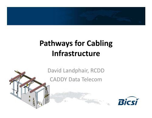
<strong>Pathways</strong> <strong>for</strong> <strong>Cabling</strong><br />
I<strong>Infrastructure</strong> f t t<br />
David Landphair, RCDD<br />
CADDY Data Telecom
Today’s y Content<br />
How to design and install the proper support<br />
systems <strong>for</strong> cost-effectiveness, code-compliance<br />
and long-term integrity of horizontal and vertical<br />
structured t t d cabling. bli<br />
Continuous pathway alternatives such as J-Hooks,<br />
bridle rings rings, cable pulleys pulleys, and other technologies<br />
will be discussed <strong>for</strong> overhead, wall, and under floor<br />
applications.
Industry y Changes g<br />
• The industry has changed much since the 80’s break<br />
up of AT&T and the RBOC’s RBOC s<br />
• <strong>Cabling</strong> has changed with the times<br />
– station wire <strong>for</strong> telephones<br />
– IBM System 3270’s, IBM System 34,36,38, RG62A/U coax,<br />
Twin-Ax, Wang-Net g – Belden 9269, 9207, 9555<br />
– Nevada-Western, balun’s <strong>for</strong> coax and twinax …<br />
– CAT3, CAT4 (<strong>for</strong> a couple of weeks), CAT5, CAT5e, CAT5E,<br />
CAT6, Augmented CAT6, CAT6A, CAT7, CAT7A … ?<br />
– Fiber has gone from 50/125 to 62.5/125 back to 50/125
Pathway y Changes g<br />
• From everything in conduit to …<br />
• Open Architecture<br />
– Cable Tray<br />
– Non-Continuous Supports<br />
– Combinations
<strong>Infrastructure</strong><br />
• <strong>Cabling</strong> infrastructure is being pushed to its<br />
li limits i and d the h potential i l weakest k li link k iis<br />
not<br />
always the cable, connectivity, or patch cords<br />
bbut the h pathways h and d hhow the h cable bl iis<br />
physically being installed<br />
• This is true <strong>for</strong> both copper and fiber systems
Wide Based vs. Narrow Based Supports<br />
• Prior to the 90’s, the primary non-continuous<br />
pathway was the bridle ring ring, cable tie tie, wire wire, string string,<br />
ceiling grid supports, electrician’s tape, etc. – narrow<br />
based products<br />
• As cables increased in per<strong>for</strong>mance, a wide based<br />
non-continuous support pp was needed that would<br />
provide the necessary bend radius support and<br />
distributed load on the load bearing surfaces<br />
– The “J-hook” was introduced by <strong>ERICO</strong> CADDY in 1995 to<br />
meet the needs of the fast changing industry
The Need For Wide Based Supports<br />
• TIA 568-C<br />
– 5321C 5.3.2.1 Copper CCable bl - CCable bl bend b d radius di may<br />
vary depending on the cable condition during<br />
installation (tensile load) and after installation<br />
when the cable is at rest (no-load). The minimum<br />
inside bend radius, under no-load or load, <strong>for</strong> 4pair<br />
balanced twisted twisted-pair pair cable shall be four<br />
times the cable diameter. For example, a cable<br />
diameter of 9 mm (0.354 in) requires a minimum<br />
bbend d radius di of f 36 mm (1.5 (1 5 i in). ) The Th minimum i i bend b d<br />
radius, under no-load or load, <strong>for</strong> multi-pair cable<br />
shall follow the manufacturer’s guidelines.
The Need For Wide Based Supports<br />
• TIA 568-C<br />
– 5.4.1 Fiber Cable<br />
• 2-4 strand inside plant fiber 2”/1” –load/no load<br />
• MMost t other th fib fiber iis 20 times ti O.D O D under d load l d and d<br />
10 times O.D. no load<br />
• New fiber designs have significantly decreased<br />
these requirements and the manufacturers<br />
guidelines <strong>for</strong> installation should be followed.
As Speeds Increase, Cable Designs Change<br />
• CAT3 to CAT5 - .187 to .19<br />
• CAT5 to CAT5E -.19 19 to .20 20<br />
• CAT5E to CAT6 - .20 to .23<br />
• When Augmented CAT6 was first introduced introduced, the<br />
cable could be as large as .5”<br />
• CAT6A is now .30-.32 or less due to the engineering g g<br />
ef<strong>for</strong>ts of the cable manufacturers<br />
• What will be the requirements and diameters of the<br />
next types of f cable bl – copper or fb fiber<br />
• Weights of cable per 1000/ft are also changing from<br />
20 lbs <strong>for</strong> CAT5e to 50 lbs <strong>for</strong> CAT6A
Types yp of Wide Based Supports pp<br />
• Various manufacturers of metal and plastic<br />
supports
Wide Based Support pp Issues<br />
• Non-Continuous pathway supports need to be UL<br />
listed – Listed by part numbers<br />
• Bend radius support – does the product really<br />
support the cable <strong>for</strong> sag between supports and <strong>for</strong><br />
direction changes – vertical to horizontal or around<br />
corners<br />
• Bend radius support <strong>for</strong> cable in all sizes of J-hooks –<br />
are the supports wide enough to support the bend<br />
radius requirement<br />
• Does the J-Hook support the load of CAT6 & 6A?
Let’s Go Racing g –NASCAR Style y
Pathway y Standard – TIA 569-C<br />
• TIA 569-C.9.7<br />
– NNon-continuous ti supports t shall h ll bbe llocated t d at t iintervals t l not t<br />
to exceed 1.5 m (5 ft.). Non-continuous supports shall be<br />
selected to accommodate the immediate and anticipated<br />
quantity, weight, and per<strong>for</strong>mance requirements of cables.<br />
• It is recommended not to make long runs exactly 5 ft<br />
apart d due to “h “harmonics” ” issues per cable bl<br />
manufacturers<br />
• NNon-continuous ti pathways th ddo not t need d tto bbe bbonded d d<br />
together or grounded (see 2011 NEC 250.92.A.1)
Other Standards Based Issues<br />
• TIA 568-C.5.3.1 – maximum pulling<br />
tension<br />
– The pulling tension <strong>for</strong> a 4-pair<br />
balanced twisted-pair twisted pair cable shall<br />
not exceed 110 N (25 lbf) during<br />
installation. For multipair cable,<br />
manufacturer’s f t ’ pulling lli ttension i<br />
guidelines shall be followed.<br />
• It is a best practice to keep the<br />
sag between supports at a<br />
maximum of 300 mm (12”) (12 )
Other Standards Based Issues<br />
• Use cost effective<br />
cable pulleys<br />
manufactured by<br />
several companies to<br />
minimize the pulling<br />
tension on cables and<br />
maintain the maximum<br />
25 lbf tension<br />
• Reusable pulleys<br />
available from less<br />
than $20 to more than<br />
$100
Pictures of Quality y<br />
Installations
Pathway y Standard – TIA 569-C<br />
• TIA 569-C.9.4.2.2<br />
– A minimum clearance of 75mm (3 in) clear vertical space<br />
shall be available above the ceiling tiles <strong>for</strong> the cabling and<br />
pathway<br />
• Critical to use approved pathways and supports <strong>for</strong><br />
the safety of fireman and employees in case of an<br />
event<br />
– Recent articles in reference to a fire in London April 6,<br />
2010 hhave bbeen circulating i l i which hi h stated d that h two fi firemen<br />
died due in part to being tangled in cabling that had fallen<br />
from the ceiling – Shirley Towers event
Other Standards Based Issues<br />
• Non-continuous pathways must<br />
con<strong>for</strong>m f to the h requirements i of f<br />
NEC 300.11 above the ceiling grid<br />
– Electrical/communication/security wiring<br />
methods in a suspended ceiling must be<br />
installed on independent p support pp wires/rods /<br />
– Per the 2011 NEC, all suspended ceilings<br />
applications must have visually distinguishable<br />
independent independent support support wires<br />
wires<br />
– Wire must be affixed at both ends to minimize<br />
movement
Per<strong>for</strong>mance Questions<br />
• J-hooks can provide equal or better<br />
per<strong>for</strong>mance characteristics vs vs. basket tray<br />
– BICSI Vegas 2007 presentation by <strong>ERICO</strong> stated<br />
that CAT6 cable in a 6 around 1 worst case<br />
scenario installed in a 90 meter run at<br />
transmission speeds up to 10Gb and frequencies<br />
up to 500 MH MHz per<strong>for</strong>med f d slightly li h l bbetter than h<br />
basket tray and ladder<br />
– The cable separation between supports provides<br />
the space between cables necessary to minimize<br />
Alien Cross-Talk issues
Large g Capacity p y Options p<br />
• J-hook “trees” offer capacity and cable<br />
management<br />
– Many J-hook size options<br />
– Cable segmentation <strong>for</strong> data, security/fire, fiber,<br />
nurse call, A/V – colored J-hook options<br />
– Flexibility<br />
– Smaller cable bundles – less chance <strong>for</strong><br />
overloading l di pathways h<br />
– Ease of removing “abandoned” cable per the NEC
Large g Capacity p y Options p
Other Considerations<br />
• Compared to conventional wire<br />
basket tray<br />
– Up to 88% less steel used<br />
– Up to 75% labor installation cost<br />
savings<br />
– Per<strong>for</strong>mance is comparable to tray<br />
systems<br />
– Grounding & bonding are not required<br />
<strong>for</strong> non-continuous metal pathways<br />
– Easier to reconfigure <strong>for</strong> MAC work
BICSI Approved pp White Paper p<br />
• Evolution of J-Hook Systems – April 2011<br />
– By Ray Keden, RCDD & ITS Technician<br />
• Electrical Engineer with 45+ years of experience in the<br />
datacom industry in Europe and the UU.S. S<br />
• Principal member of the NEC Panel 3, expert member<br />
of ISO/IEC JTC SC25 WG3, member of the BICSI Codes &<br />
Standards committees and the TIA-TR42 Engineering<br />
committee<br />
• 2006 recipient of the Harr Harry Pfister award a ard <strong>for</strong> EExcellence cellence<br />
in the Telecommunications Industry<br />
– www.bicsi.org/pdf/whitepapers
Wall Installation Issues<br />
• Many facilities are being designed with conduit stubs<br />
in the walls<br />
– The problem being with multiple CAT6/6A or a<br />
combination of copper pp and fiber, , the standard 4 square q &<br />
4-11/16 boxes are not large enough to maintain the<br />
minimum bend radius and separation of the cables<br />
– TTraditional diti lllow voltage lt new construction t ti mounting ti<br />
brackets do not allow <strong>for</strong> attaching the conduit stub to the<br />
bracket<br />
– Consideration needs to be given to determine if the<br />
location is a fire-rated wall or not
New Products Introduced<br />
• Multiple manufacturers have developed closed box<br />
and open bracket systems that now meet the bend<br />
requirements<br />
5” Box from<br />
Randl Industries, Inc.<br />
Open bracket<br />
design g from<br />
CADDY
Raised Floor Applications<br />
pp<br />
• History – <strong>Cabling</strong> over time has gone from<br />
above the cabinets to below the raised floors<br />
and are now going back to above the cabinets<br />
• Reason – Better air flow through the raised<br />
floor plenum<br />
• Large capacity cable pathways were creating<br />
air dams which affected the HVAC<br />
per<strong>for</strong>mance by as much as 30%<br />
• Are there options <strong>for</strong> small cable supports <strong>for</strong><br />
below the floor?
Raised Floor Solutions
Cable Tray y Support pp Options p<br />
• Traditional threaded rod, beam clamps, strut<br />
f<strong>for</strong> trapeze supports, standard d d “ “nuts” ”<br />
• “Aircraft type cable” UL rated systems that<br />
several manufacturers offer in different<br />
configurations <strong>for</strong> time savings installations<br />
• New threaded beam clamps, strut/channel<br />
nuts, , ceiling g anchors available in the market<br />
<strong>for</strong> time saving installations
Cable Support pp Systems y<br />
• Load ratings of 44<br />
to 100 to 200 lbs lbs.<br />
• 5:1 safety factor –<br />
UL 2239 has 3:1<br />
rating required<br />
• UL Fire & Plenum<br />
rated t d<br />
• Various lengths<br />
available typically<br />
from 1 – 10 m<br />
length (3 – 33ft)
New Threaded Rod Systems y<br />
• ROD LOCK – push in system vs. threading into<br />
the h ffollowing ll i parts<br />
– Beam Clamp<br />
– Strut/Channel Nut<br />
– Ceiling Anchor<br />
– SN Series Nut – ¼”, 3/8”, ½”
New Threaded Rod Systems y<br />
• Beam Clamp –<br />
500 lb<br />
• Strut/Channel Nut<br />
– 750 lb<br />
• Ceiling Anchor –<br />
660 lb<br />
• SN Series Nut –<br />
¼”, ¼, 3/8 3/8”, , ½½”
Questions?
THANK YOU!


