
You also want an ePaper? Increase the reach of your titles
YUMPU automatically turns print PDFs into web optimized ePapers that Google loves.
Tél. +<strong>33</strong> 1 60 57 30 00 Fax +<strong>33</strong> 1 60 57 30 15 www.sileccable.com<br />
Rue de Varennes prolongée – 77876 MONTEREAU CEDEX – FRANCE<br />
SAS au capital de 60 037 000 - 484 920 194<br />
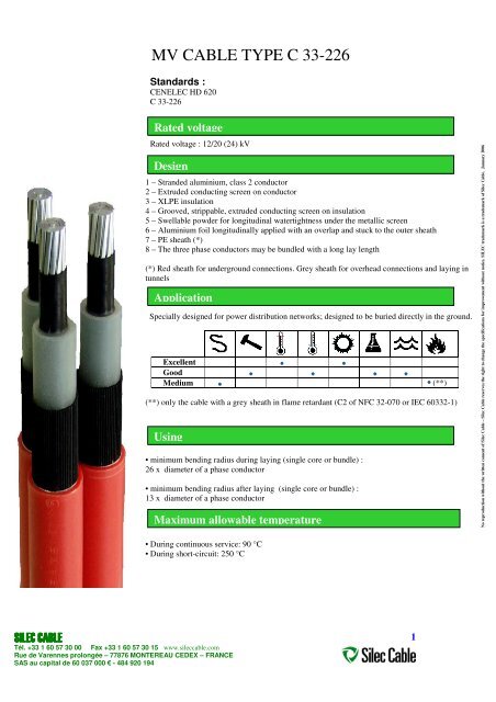
<strong>MV</strong> <strong>CABLE</strong> <strong>TYPE</strong> C <strong>33</strong>-<strong>226</strong><br />
Standards :<br />
CENELEC HD 620<br />
C <strong>33</strong>-<strong>226</strong><br />
Rated voltage<br />
Rated voltage : 12/20 (24) kV<br />
Design<br />
1 – Stranded aluminium, class 2 conductor<br />
2 – Extruded conducting screen on conductor<br />
3 – XLPE insulation<br />
4 – Grooved, strippable, extruded conducting screen on insulation<br />
5 – Swellable powder for longitudinal watertightness under the metallic screen<br />
6 – Aluminium foil longitudinally applied with an overlap and stuck to the outer sheath<br />
7 – PE sheath (*)<br />
8 – The three phase conductors may be bundled with a long lay length<br />
(*) Red sheath for underground connections. Grey sheath for overhead connections and laying in<br />
tunnels<br />
Application<br />
Specially designed for power distribution networks; designed to be buried directly in the ground.<br />
Excellent<br />
Good<br />
Medium (**)<br />
(**) only the cable with a grey sheath in flame retardant (C2 of NFC 32-070 or IEC 60<strong>33</strong>2-1)<br />
Using<br />
• minimum bending radius during laying (single core or bundle) :<br />
26 x diameter of a phase conductor<br />
• minimum bending radius after laying (single core or bundle) :<br />
13 x diameter of a phase conductor<br />
Maximum allowable temperature<br />
• During continuous service: 90 °C<br />
• During short-circuit: 250 °C<br />
1<br />
No reproduction without the written consent of <strong>Silec</strong> <strong>Cable</strong> – <strong>Silec</strong> <strong>Cable</strong> reserves the right to change the specifications for improvement without notice. SILEC trademark is a trademark of <strong>Silec</strong> <strong>Cable</strong>. January 2006
Identification and outer marking<br />
C <strong>33</strong>-<strong>226</strong> (continued)<br />
SILEC Day Year C <strong>33</strong> <strong>226</strong> Cross-section Al 12/20 (24) kV<br />
SIPRELEC 23 POPY (1) G2 SC 0,7 AT T -10/50 (2) PHASE 1 (or 2 or 3)<br />
(1) Reference for the cable fittings<br />
(2) T 0/35 for grey-sheathed cable<br />
Length marking on one conductor.<br />
Dimension<br />
<strong>CABLE</strong> Approximate outer diameter mm<br />
Tél. +<strong>33</strong> 1 60 57 30 00 Fax +<strong>33</strong> 1 60 57 30 15 www.sileccable.com<br />
Rue de Varennes prolongée – 77876 MONTEREAU CEDEX – FRANCE<br />
SAS au capital de 60 037 000 - 484 920 194<br />
Approximate<br />
weight<br />
kg/km<br />
Maximum allowable pulling<br />
force, daN<br />
1x50 mm² 29,0 700 150<br />
1x95 mm² 32,0 950 285<br />
1x150 mm² 32,0 1000 450<br />
1x240 mm² 36,5 1400 720<br />
3x50 mm² 62.5 2100 450<br />
3x95 mm² 69,0 2800 855<br />
3x150 mm² 69,0 3050 1350<br />
3x240 mm² 78,5 4150 2160<br />
Electrical characteristics<br />
Cross-section, mm²<br />
Item 50 95 150 240<br />
DC maximum resistance of the conductor at 20°C, Ω / km 0,641 0,320 0,206 0,125<br />
AC apparent resistance of the conductor at 90°C, Ω / km (1) 0,820 0,410 0,265 0,160<br />
Self-induction coefficient, mH / km (1) 0,440 0,400 0,350 0,<strong>33</strong>0<br />
Capacitance, µF / km 0,180 0,220 0,300 0,360<br />
(1) These values are applicable to a three-phase system made of three conductors bundled or in joined trefoil formation.<br />
For other cross-sections, please contact us.<br />
2<br />
No reproduction without the written consent of <strong>Silec</strong> <strong>Cable</strong> – <strong>Silec</strong> <strong>Cable</strong> reserves the right to change the specifications for improvement without notice. SILEC trademark is a trademark of <strong>Silec</strong> <strong>Cable</strong>. January 2006
Maximum allowable ampacity<br />
Tél. +<strong>33</strong> 1 60 57 30 00 Fax +<strong>33</strong> 1 60 57 30 15 www.sileccable.com<br />
Rue de Varennes prolongée – 77876 MONTEREAU CEDEX – FRANCE<br />
SAS au capital de 60 037 000 - 484 920 194<br />
C <strong>33</strong>-<strong>226</strong> (continued)<br />
Cross section, mm²<br />
Winter<br />
Buried<br />
Summer<br />
50 205 170<br />
95 300 245<br />
150 385 310<br />
240 505 410<br />
Ampacity in Ampere is calculated for a three phase system, with the below thermal hypothesis, without any electric parallel nor<br />
thermal proximity.:<br />
SUMMER:<br />
• soil temperature : 20 °C<br />
• soil thermal resistivity : 1,2 K m / W<br />
WINTER:<br />
• soil temperature : 10 °C<br />
• soil thermal resistivity : 0,85 K m / W<br />
For other cross-sections, please contact us.<br />
Allowable ampacity during short-circuit in the screen<br />
Cross-section, mm² Icc, A during 1 sec<br />
50 2500<br />
95 2700<br />
150 2700<br />
240 3200<br />
For other cross-sections, please contact us.<br />
3<br />
No reproduction without the written consent of <strong>Silec</strong> <strong>Cable</strong> – <strong>Silec</strong> <strong>Cable</strong> reserves the right to change the specifications for improvement without notice. SILEC trademark is a trademark of <strong>Silec</strong> <strong>Cable</strong>. January 2006
Tél. +<strong>33</strong> 1 60 57 30 00 Fax +<strong>33</strong> 1 60 57 30 15 www.sileccable.com<br />
Rue de Varennes prolongée – 77876 MONTEREAU CEDEX – FRANCE<br />
SAS au capital de 60 037 000 - 484 920 194<br />
ALL GROUND <strong>CABLE</strong> <br />
type UTE C <strong>33</strong>-223 or NF C <strong>33</strong>-223<br />
Standards :<br />
UTE C <strong>33</strong>-223 of December 1999 CENELEC HD 620<br />
NFC <strong>33</strong>-223 IEC 60 502-2<br />
Rated voltage<br />
This design can be manufactured for all rated voltage of IEC 60502 - 2<br />
Design<br />
• Stranded conductor, class 2<br />
• Extruded conducting screen on conductor<br />
• XLPE insulation<br />
• Grooved, strippable, extruded conducting screen on insulation<br />
• Swellable powder for longitudinal watertightness under the metallic screen<br />
• Aluminium foil longitudinally applied with an overlap and stuck to the outer sheath,<br />
• PVC sheath,<br />
• Strippable, grooved, TPR sheath<br />
• The three phase conductors may be bundled with a long lay length<br />
Using<br />
<strong>Cable</strong> for <strong>MV</strong> distribution networks.<br />
It can be buried directly in all grounds, and is specially adapted for « hard » ground.<br />
Mainly, its design prevents from adding sand in the trench bottom, and the trench can be<br />
filled back with original soil.<br />
Very good<br />
Good<br />
Medium<br />
Setting up<br />
• the minimum bending radius during installation is the same that NF C <strong>33</strong>-223 or<br />
UTE C <strong>33</strong>-223 (see dimension)<br />
• the minimum bending radius after installation is the same that NF C <strong>33</strong>-223 or<br />
UTE C <strong>33</strong>-223 (see dimension)<br />
Fitting of a termination or a joint :<br />
- Once the grooved outer sheath has been removed with the usual tool, the fitting of a termination or<br />
a joint is the same as for NF C <strong>33</strong>-223 or UTE C <strong>33</strong>-223<br />
4<br />
No reproduction without the written consent of <strong>Silec</strong> <strong>Cable</strong> – <strong>Silec</strong> <strong>Cable</strong> reserves the right to change the specifications for improvement without notice. SILEC trademark is a trademark of <strong>Silec</strong> <strong>Cable</strong>. January 2006
• Continuous service: 90 °C<br />
• Short-circuit in the conductor: 250 °C<br />
• Short-circuit in the metallic screen : 200 °C<br />
Tél. +<strong>33</strong> 1 60 57 30 00 Fax +<strong>33</strong> 1 60 57 30 15 www.sileccable.com<br />
Rue de Varennes prolongée – 77876 MONTEREAU CEDEX – FRANCE<br />
SAS au capital de 60 037 000 - 484 920 194<br />
All Ground <strong>Cable</strong> type UTE C <strong>33</strong>-223 or NF C <strong>33</strong>-223 (continued)<br />
Maximum allowable temperatures<br />
Identification and outer marking<br />
SILEC « Batch number » « Standard » cross section AL 12/20 (24) kV<br />
SIPRELEC 23 Ec=0.2 mm PHASE 1 (or 2 or 3) ALL GROUND <strong>CABLE</strong><br />
Length marking can be indicated on one phase conductor.<br />
Dimension<br />
Approximate Approximate Minimum Minimum Maximum<br />
outer diameter weight bending bending radius pulling force<br />
ARTICLE<br />
radius after<br />
laying<br />
during laying<br />
mm<br />
mm<br />
kg/km mm<br />
daN<br />
1 x 50 mm² 39,5 1400 400 800 150<br />
1 x 95 mm² 42.5 1700 450 900 285<br />
1 x 150 mm² 43,5 1850 450 900 450<br />
1 x 240 mm² 48,0 2350 500 1000 720<br />
3 x 50 mm² 84,5 4200 400 800 450<br />
3 x 95 mm² 92,0 5100 450 900 855<br />
3 x 150 mm² 93,5 5500 450 900 1350<br />
3 x 240 mm² 103,5 7000 500 1000 2160<br />
Electrical characteristics<br />
Cross Section, mm²<br />
50 95 150 240<br />
Item<br />
Maximum DC resistance at 20 °C, Ω / km 0,641 0,320 0,206 0,125<br />
AC apparent resistance of the conductor at 90 °C,<br />
Ω / km<br />
0,820 0,410 0,260 0,160<br />
Self-induction coefficient mH / km (1) 0,500 0,450 0,420 0,380<br />
Capacitance, µF / km<br />
0,180 0,210 0,290 0,360<br />
(1) Calculated for three bundled cables or three cables in a joined trefoil formation.<br />
For other sections, call us .<br />
5<br />
No reproduction without the written consent of <strong>Silec</strong> <strong>Cable</strong> – <strong>Silec</strong> <strong>Cable</strong> reserves the right to change the specifications for improvement without notice. SILEC trademark is a trademark of <strong>Silec</strong> <strong>Cable</strong>. January 2006
Maximum allowable ampacity<br />
Tél. +<strong>33</strong> 1 60 57 30 00 Fax +<strong>33</strong> 1 60 57 30 15 www.sileccable.com<br />
Rue de Varennes prolongée – 77876 MONTEREAU CEDEX – FRANCE<br />
SAS au capital de 60 037 000 - 484 920 194<br />
All Ground <strong>Cable</strong> type UTE C <strong>33</strong>-223 or NF C <strong>33</strong>-223 (continued)<br />
Cross section, mm²<br />
Winter<br />
Buried cables<br />
Summer<br />
50 195 160<br />
95 285 235<br />
150 360 300<br />
240 480 395<br />
Ampacity is indicated in amps for a three-phase system without any thermal or electrical proximity under following<br />
thermal conditions:<br />
SUMMER:<br />
• soil temperature : 20 °C<br />
• soil thermal resistivity : 1,2 K m / W<br />
WINTER:<br />
• soil temperature : 10 °C<br />
• soil thermal resistivity : 0,85 K m / W<br />
For other sections, call us .<br />
6<br />
No reproduction without the written consent of <strong>Silec</strong> <strong>Cable</strong> – <strong>Silec</strong> <strong>Cable</strong> reserves the right to change the specifications for improvement without notice. SILEC trademark is a trademark of <strong>Silec</strong> <strong>Cable</strong>. January 2006
ALL GROUND <strong>CABLE</strong> TM<br />
type C <strong>33</strong>-<strong>226</strong><br />
Standards :<br />
UTE C <strong>33</strong> <strong>226</strong>,<br />
HD 620,<br />
Rated voltage<br />
Rated voltage: 12/20 (24) kV<br />
Design<br />
• Stranded conductor, class 2<br />
• Extruded conducting screen on conductor<br />
• XLPE insulation<br />
• Grooved, strippable, extruded conducting screen on insulation<br />
• Swellable powder for longitudinal watertightness under the metallic screen<br />
• Aluminium foil longitudinally applied with an overlap and stuck to the outer sheath,<br />
• PE sheath,<br />
• Strippable, grooved, TPR sheath<br />
• The three phase conductors may be bundled with a long lay length<br />
Using<br />
<strong>Cable</strong> for <strong>MV</strong> distribution networks.<br />
It can be buried directly in all grounds, and is specially adapted for « hard » ground.<br />
Mainly, its design prevents from adding sand in the trench bottom, and the trench can be filled with<br />
original soil.<br />
Very good<br />
Good<br />
Medium<br />
Setting up<br />
• the minimum bending radius during installation is the same that C <strong>33</strong>-<strong>226</strong> (see dimension)<br />
• the minimum bending radius after installation is the same C <strong>33</strong>-<strong>226</strong> (see dimension)<br />
• Fitting of a termination or a joint :<br />
- Once the grooved outer sheath has been removed with the usual tool, the fitting a termination or a joint<br />
is the same as for standard <strong>MV</strong> cables<br />
Tél. +<strong>33</strong> 1 60 57 30 00 Fax +<strong>33</strong> 1 60 57 30 15 www.sileccable.com<br />
Rue de Varennes prolongée – 77876 MONTEREAU CEDEX – FRANCE<br />
SAS au capital de 60 037 000 - 484 920 194<br />
7<br />
No reproduction without the written consent of <strong>Silec</strong> <strong>Cable</strong> – <strong>Silec</strong> <strong>Cable</strong> reserves the right to change the specifications for improvement without notice. SILEC trademark is a trademark of <strong>Silec</strong> <strong>Cable</strong>. January 2006
Maximum allowable temperatures<br />
• Continuous service: 90 °C<br />
• Short-circuit in the conductor: 250 °C<br />
Identification and outer marking<br />
SILEC Day Year C <strong>33</strong> <strong>226</strong> Cross-section Al 12/20 (24) kV<br />
Tél. +<strong>33</strong> 1 60 57 30 00 Fax +<strong>33</strong> 1 60 57 30 15 www.sileccable.com<br />
Rue de Varennes prolongée – 77876 MONTEREAU CEDEX – FRANCE<br />
SAS au capital de 60 037 000 - 484 920 194<br />
All Ground <strong>Cable</strong> type C <strong>33</strong>-<strong>226</strong> (continued)<br />
SIPRELEC 23 POPY (1) G2 SC 0,7 AT T -10/50 (2) PHASE 1 (or 2 or 3) ALL GROUND <strong>CABLE</strong><br />
(3) Reference for the cable fittings<br />
(4) T 0/35 for grey-sheathed cable<br />
Metric marking can be indicated on one phase conductor.<br />
Dimension<br />
ARTICLE<br />
Approximate<br />
outer diameter<br />
mm<br />
Approximate<br />
weight<br />
kg/km<br />
Minimum<br />
bending radius<br />
after laying<br />
mm<br />
Minimum<br />
bending radius<br />
during laying<br />
mm<br />
Maximum<br />
pulling force<br />
1 x 50 mm² 38,0 1200 400 800 150<br />
1 x 95 mm² 41,0 1450 450 900 285<br />
1 x 150 mm² 41,0 1550 450 900 450<br />
1 x 240 mm² 45,5 1950 500 1000 720<br />
3 x 50 mm² 81,0 3550 400 800 450<br />
3 x 95 mm² 88,0 4350 450 900 855<br />
3 x 150 mm² 88,0 4600 450 900 1350<br />
3 x 240 mm² 97,5 5900 500 1000 2160<br />
daN<br />
8<br />
No reproduction without the written consent of <strong>Silec</strong> <strong>Cable</strong> – <strong>Silec</strong> <strong>Cable</strong> reserves the right to change the specifications for improvement without notice. SILEC trademark is a trademark of <strong>Silec</strong> <strong>Cable</strong>. January 2006
Electrical characteristics<br />
Tél. +<strong>33</strong> 1 60 57 30 00 Fax +<strong>33</strong> 1 60 57 30 15 www.sileccable.com<br />
Rue de Varennes prolongée – 77876 MONTEREAU CEDEX – FRANCE<br />
SAS au capital de 60 037 000 - 484 920 194<br />
All Ground <strong>Cable</strong> type C <strong>33</strong>-<strong>226</strong> (continued)<br />
(1) Calculated for three bundled cables or three cables in a joined trefoil formation.<br />
SUMMER:<br />
• soil temperature : 20 °C<br />
• soil thermal resistivity : 1,2 K m / W<br />
WINTER:<br />
• soil temperature : 10 °C<br />
• soil thermal resistivity : 0,85 K m / W<br />
Cross section, mm²<br />
Characteristics<br />
Maximum DC resistance at 20 °C, Ω / km 0,641 0,320 0,206 0,125<br />
AC apparent resistance of the conductor at 90 °C, Ω / km 0,820 0,410 0,270 0,160<br />
Self-induction coefficient, mH / km (1) 0,500 0,450 0,400 0,370<br />
Capacitance, µF / km 0,180 0,220 0,300 0,360<br />
For other sections, please contact us .<br />
Maximum allowable ampacity under continuous load<br />
For other sections, please contact us .<br />
Cross Section, mm² Icc, A during 1 second<br />
50 1250<br />
95 2200<br />
150 2500<br />
240 2500<br />
For other sections, please contact us .<br />
50 95 150 240<br />
Cross section, mm²<br />
Winter<br />
Buried cables<br />
Summmer<br />
50 195 165<br />
95 290 240<br />
150 370 305<br />
240 490 400<br />
.<br />
Ampacity is indicated in amps for a three-phase system without any thermal or electrical proximity under following thermal<br />
conditions:<br />
Maximum allowable ampacity in the screen under short-circuit<br />
9<br />
No reproduction without the written consent of <strong>Silec</strong> <strong>Cable</strong> – <strong>Silec</strong> <strong>Cable</strong> reserves the right to change the specifications for improvement without notice. SILEC trademark is a trademark of <strong>Silec</strong> <strong>Cable</strong>. January 2006