

SCAN 5-2 - Northwest Stoves Ltd.
SCAN 5-2 - Northwest Stoves Ltd.
SCAN 5-2 - Northwest Stoves Ltd.

Create successful ePaper yourself
Turn your PDF publications into a flip-book with our unique Google optimized e-Paper software.
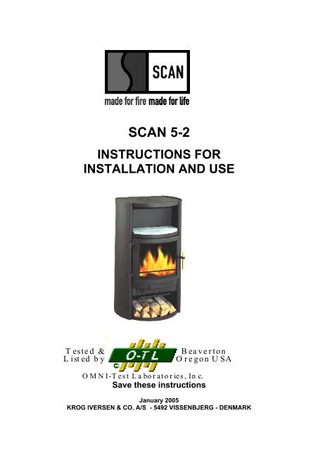
<strong>SCAN</strong> 5-2<br />
INSTRUCTIONS FOR<br />
INSTALLATION AND USE<br />
Tested &<br />
Listed by<br />
Beaverton<br />
O regon U SA<br />
OMNI-Test Laboratories, Inc.<br />
Save these instructions<br />
January 2005<br />
KROG IVERSEN & CO. A/S - 5492 VISSENBJERG - DENMARK
Table of Contents:<br />
1. INTRODUCTION .................................................................................................................................................................3<br />
CAUTIONS:............................................................................................................................................................4<br />
2. INSTALLATION ..................................................................................................................................................................5<br />
Pre Installation Check List:........................................................................................................................................5<br />
The floor ....................................................................................................................................................................6<br />
Ceiling height:............................................................................................................................................................6<br />
Combustible Wall Clearance for top vent installation: ..............................................................................................7<br />
Combustible Wall Clearance for rear vent installation: .............................................................................................7<br />
Draft Requirements:...................................................................................................................................................8<br />
Chimney Installation:.................................................................................................................................................8<br />
Factory Built Chimney...............................................................................................................................................8<br />
Masonry Chimney......................................................................................................................................................8<br />
Top vent installation ..................................................................................................................................................9<br />
Chimney connection ................................................................................................................................................10<br />
Rear vent installation: ..............................................................................................................................................11<br />
Chimney height requirements: .................................................................................................................................13<br />
3. INSTRUCTIONS FOR USE ...............................................................................................................................................14<br />
Ash Drawer:.............................................................................................................................................................14<br />
Ash Grate:................................................................................................................................................................14<br />
Baffle Plates:............................................................................................................................................................14<br />
Glass: .......................................................................................................................................................................14<br />
Smoke Detectors:.....................................................................................................................................................14<br />
Room Ventilation: ................................................................................................................................................................14<br />
Fire Bricks: ..............................................................................................................................................................14<br />
Ceramic Packing Cord: ............................................................................................................................................15<br />
Protected Wall Reduced Clearances: .......................................................................................................................15<br />
Combustion Air Supply: ..........................................................................................................................................15<br />
Draft Requirements:.................................................................................................................................................15<br />
4. OPERATION.......................................................................................................................................................................16<br />
Fueling the Stove: ....................................................................................................................................................16<br />
To start a fire:...........................................................................................................................................................16<br />
Refueling: ................................................................................................................................................................17<br />
5. MAINTENANCE................................................................................................................................................................18<br />
Ash Disposal and Removal:.....................................................................................................................................18<br />
Cleaning of Stove: ...................................................................................................................................................18<br />
Replacement part list: ..............................................................................................................................................21<br />
Creosote Formation and the Need for Removal:......................................................................................................21<br />
Door Glass: ..............................................................................................................................................................21<br />
6. TROUBLESHOOTING ......................................................................................................................................................22<br />
7. WARRANTY ......................................................................................................................................................................23<br />
2
We welcome you as a new owner of a <strong>SCAN</strong> wood stove. In purchasing a <strong>SCAN</strong> stove you have<br />
joined the growing ranks of concerned individuals whose selection of energy systems reflects both a<br />
concern for the environment and aesthetics. The <strong>SCAN</strong> stove is one of the finest home wood stoves in<br />
the world over. This manual will explain the installation, operation and maintenance of the <strong>SCAN</strong><br />
stove. Please familiarize yourself with the owner’s manual before operating your stove and save the<br />
manual for future reference. Included are helpful hints and suggestions that will make the operation<br />
and maintenance of your new stove an easier and more enjoyable experience. We offer our continued<br />
support and guidance to help you achieve the maximum benefit and enjoyment from your <strong>SCAN</strong><br />
stove.<br />
1. INTRODUCTION<br />
PLEASE READ THIS ENTIRE MANUAL CAREFULLY BEFORE YOU INSTALL AND USE YOUR<br />
NEW <strong>SCAN</strong> STOVE, FAILURE TO FOLLOW INSTRUCTIONS MAY RESULT IN PROPERTY<br />
DAMAGE, BODILY INJURY OR LOSS OF LIFE. THIS MANUAL CONTAINS IMPORTANT USER<br />
INFORMATION. KEEP THIS MANUAL WITH THE STOVE AFTER INSTALATION IS COMPLETE.<br />
Safety and environmental testing.<br />
<strong>SCAN</strong> 5 stoves have been tested by OMNI-Test Laboratories, Inc. of Beaverton, Oregon, and are<br />
safety listed by OMNI to UL 1482, ULC-S627 and EPA certified.<br />
Important information:<br />
No other <strong>SCAN</strong> stove has the same registration number as yours. The registration number is fixed to<br />
the stove. In case of complaints we request that you have the registration number.<br />
Items included<br />
In the <strong>SCAN</strong> stove you will find a service box containing the following items:<br />
1 oven mitten<br />
1 handle to operate the shake grate<br />
1 set of fittings for the flue collar<br />
1 set of screws and hexagon spanners<br />
1 bag containing fire starters for the first lightning<br />
2 plastic plugs for covering the transportation holes in the wood compartment.<br />
3
CAUTIONS:<br />
KEEP ASH DRAWER CLOSED DURING FIRING IN THIS STOVE, ASH DRAWER MAY BE<br />
OPENED FOR A MAXIMUM OF 5 MINUTES DURING FIRE STARTUP. USE A METAL CONTAINER<br />
WITH A TIGHT FITTING LID TO DISPOSE OF ASHES.<br />
NEVER USE GASOLINE, GASOLINE-TYPE LANTERN FUEL, KEROSENE, CHARCOAL LIGHTER<br />
FLUID, OR SIMILAR LIQUIDS TO START OR “FRESHEN UP” A FIRE IN THIS STOVE. KEEP ALL<br />
SUCH LIQUIDS WELL AWAY FROM THE STOVE WHILE IT IS IN USE.<br />
DO NOT BURN GARBAGE OR FLAMMABLE FLUIDS SUCH AS GASOLINE, NAPHTHA OR<br />
ENGINE OIL.<br />
THIS STOVE IS HOT WHILE IN OPERATION, DO NOT TOUCH, KEEP CHILDREN AWAY.<br />
CONTACT MAY CAUSE SKIN BURNS. USE GLOVES WHEN STOKING THE FIRE.<br />
DO NOT CONNECT THIS STOVE TO A CHIMNEY FLUE CONNECTED TO ANOTHER STOVE OR<br />
APPLIANCE.<br />
DO NOT CONNECT TO ANY AIR DISTRIBUTION DUCT OR SYSTEM.<br />
DO NOT INSTALL IN A MOBILE HOME.<br />
BE SURE TO ALLOW AN ADEQUATE SOURCE OF FRESH AIR INTO THE ROOM WHERE THE<br />
STOVE IS OPERATING (SEE ROOM VENTILATION PAGE 12 AND COMBUSTION AIR SUPPLY<br />
PAGE 13).<br />
DO NOT OPERATE THE STOVE WITHOUT THE FIREBOX BAFFLE PLATES PROPERLY<br />
INSTALLED.<br />
BUILD FIRES DIRECTLY UPON THE HEARTH INSIDE THE STOVE. DO NOT USE GRATES,<br />
IRONS OR ANY OTHER METHOD TO ELEVATE THE FIRE.<br />
THE <strong>SCAN</strong> STOVES ARE NOT USABLE FOR FIREPLACE INSTALLATION.<br />
4
2. INSTALLATION<br />
PRECAUTION<br />
IF YOUR <strong>SCAN</strong> STOVE IS NOT PROPERLY INSTALLED, OPERATED AND MAINTAINED, A<br />
HOUSE FIRE MAY RESULT. FOR YOUR SAFETY, FOLLOW ALL INSTALLATION, OPERATION<br />
AND MAINTENANCE DIRECTIONS. CONTACT YOUR LOCAL BUILDING OFFICIALS ABOUT<br />
RESTRICTIONS AND INSTALLATION REQUIREMENTS IN YOUR AREA.<br />
Pre Installation Check List:<br />
Before you begin an installation, review your plans, check to see:<br />
1. Your stove and chimney connector will be far enough from combustible material to meet all<br />
clearance requirements.<br />
2. The floor protection is large enough and is constructed properly to meet all requirements.<br />
3. You have all necessary permits from local authorities. Your local building official is the final<br />
authority for approving your installation as safe and determining that it meets all local and state<br />
building and safety codes.<br />
The metal label permanently attached to the back of every <strong>SCAN</strong> stove shows that it has been tested<br />
to current UL and ULC safety standards, and gives the name of the testing laboratory. Clearance and<br />
installation information is also printed on the label. Local authorities will generally accept the label as<br />
evidence that, when the stove is installed according to the information on the label and in this manual,<br />
the installation meets codes and can be approved.<br />
Codes vary in different areas. Before starting the installation, review your plans with the local building<br />
authority. Your local dealer can provide any additional information needed.<br />
For any unresolved questions about installation in the USA, refer to the national Fire Protection<br />
Association’s publication ANSI/NFPA 211 Standard for Chimneys, Fireplaces, Vents and Solid Fuel<br />
Burning Appliances. For installation in Canada, refer to CSA CAN-B365, Installation Code for Solid<br />
Fuel Burning Applications and Equipment. These standards are the basis for many national codes.<br />
They are nationally recognized and are accepted by most local authorities. Your local dealer or your<br />
local building official may have a copy of these regulations.<br />
WARNING: Check all local building and safety codes before installation. The installation instructions<br />
and appropriate code requirements must be followed exactly and without compromise. Alterations to<br />
the stove are not allowed. Do not connect the stove to a chimney system serving another stove,<br />
appliance or any air distribution duct. Failure to follow these instructions will void the manufacturers<br />
warranty.<br />
NOTE: If you plan to vent your stove into an existing masonry chimney, have the chimney inspected<br />
by a local fire marshal or qualified installer. Remember that the chimney and its location on the roof<br />
heavily influent on the stove performance. An oversized flue may not provide effective draught and a<br />
flue liner may be required. (Observe draft requirements). Consult your dealer or qualified installer<br />
before final selection is made.<br />
We advise you to leave enough room to enable cleaning between the stove and the wall.<br />
5
The floor<br />
One of the main necessary precautions when installing a wood stove is to leave sufficient space<br />
between the stove (top, sides, back, front, and under stove pipes) and any other material that can<br />
catch fire.<br />
If the stove is to be installed on a combustible floor, it must be placed on a non-combustible hearth<br />
pad, which extends 8” (200mm measured from the legs) beyond the stove sides and back, and 18”<br />
(455mm measured from side and back panels) to the front<br />
NOTE: the floor protection need's only to be a standard ember protection.<br />
Floor protection A B C D<br />
USA 16" 8"<br />
Canada 18" 8" 8"<br />
Fig 1.<br />
In a rear vent installation the floor protection must also extend under the stove pipe a minimum of 2”<br />
(50mm) beyond either side of the pipe.<br />
Ceiling height:<br />
Do not install in an alcove or confined space and do not install in a room with a ceiling high below 7’<br />
(210 cm)<br />
6
Combustible Wall Clearance for top vent installation:<br />
If the stove is to be placed at side and back walls of combustible materials the following clearances<br />
must be kept<br />
Stove model A B C<br />
All models 365 mm<br />
14 inch<br />
7<br />
150 mm<br />
6 inch<br />
150 mm<br />
6 inch<br />
Combustible Wall Clearance for rear vent installation:<br />
If the stove is to be placed at side and back walls of combustible materials the following clearances<br />
must be kept:<br />
Stove model A B D<br />
All models 365 mm<br />
14 inch<br />
150 mm<br />
6 inch<br />
535 mm<br />
21"<br />
Refer to the manufacturer’s instructions concerning installation of listed connector pipe, wall thimble<br />
and chimney<br />
You have to use a double wall connector pipe<br />
Refer to the manufacturer’s instructions concerning installation of listed connector pipe, wall thimble<br />
and chimney
Draft Requirements:<br />
Scan 5.2 is only one component of the total system. The venting system is equally important for<br />
achieving the required flow of combustion air to the firebox and for safely removing unwanted<br />
combustion byproducts from the appliance. If the venting system’s design does not promote these<br />
ends, the system may not function properly. Poorly functioning venting systems may create<br />
performance problems as well as be a safety hazard (i.e. an oversized chimney may result in less than<br />
optimum performance. Installations into a large, masonry chimney may require a liner to improve<br />
performance). A draft test should read greater than .04" W.C. (Inches Water Column) and less than<br />
.08" W.C. The table below shows dimension of connection piece and data for draft requirements for<br />
the stove:<br />
Stove Connection<br />
piece<br />
Ø mm / inch<br />
All models 150 mm<br />
6” inch<br />
With Closed Doors<br />
Chimney<br />
draught<br />
Pa; inch<br />
13 Pa<br />
0.05” WC<br />
8<br />
Efficiency<br />
in %<br />
BTU<br />
63% 11,800 - 26,500<br />
The chimney draught depends on the weather conditions. In stormy weather, you may reduce the<br />
chimney draught by closing the damper in the smoke pipe (if a damper has been installed). If the<br />
chimney draught is strong, the combustion air supply must be reduced additionally.<br />
Chimney Installation:<br />
DO NOT CONNECT THIS UNIT TO A CHIMNEY FLUE SERVING ANOTHER APPLIANCE. DO<br />
NOT CONNECT TO ANY AIR DISTRIBUTION DUCT OR SYSTEM.<br />
<strong>SCAN</strong> 5.2 is listed for installation as a vertically top or rear vented stove using a listed class A<br />
(UL103HT) for Canada (CAN/ULC-S629) factory built chimney exiting through the ceiling/attic/roof.<br />
The inside diameter of the chimney, connector pipe must not be smaller than 6” (152 cm) diameter.<br />
Single wall 24 gauge MSG (0.58 – 0.71 mm) and adapter must not be smaller than 6” (152 mm), may<br />
be used in the room where the stove is installed, follow the chimney manufacturer’s instruction for<br />
installation of chimney and chimney adapter. In Canada, where passage through wall, or partition of<br />
combustible construction is desired, the installation shall conform to CAN/CSA B365.<br />
Factory Built Chimney<br />
When a metal prefabricated chimney is used, the manufacturer’s installation instructions must be<br />
followed. You must also purchase (from the same manufacturer) and install the ceiling support<br />
package or wall pass-through and “T” section package, fire stops (where needed), insulation shield,<br />
roof flashing, chimney cap, etc. Maintain proper clearance to the structure as recommended by the<br />
manufacturer. The chimney must be the required height above the roof or other obstructions for<br />
safety and proper draft operation. See page 11 for chimney termination requirements.<br />
Masonry Chimney<br />
Ensure that a masonry chimney meets the minimum standards of the National Fire Protection<br />
Association (NFPA) by having it inspected by a professional. Make sure there are no cracks, loose<br />
mortar or other signs of deterioration and blockage. Have the chimney cleaned before the stove is<br />
installed and operated. When connecting the stove through a combustible wall to a masonry chimney,<br />
special methods are needed. Refer to Combustible Wall Chimney Connector Pass-Throughs on page<br />
10 and 11.
Top vent installation<br />
Mounting of the flue collar for top vent.<br />
Turn the flue collar around and fix the brackets under the top plate.<br />
Tighten the two screws with the delivered hexagon spanner (tighten well)<br />
Required installation components:<br />
• Chimney cap<br />
• Insulated chimney<br />
• Storm collar<br />
• Roof flashing<br />
• Ceiling support box or joist<br />
shield/fire stop spacer<br />
• Chimney connector pipe<br />
• Chimney connector adapter<br />
9
Chimney connection<br />
The chimney connector is a single walled pipe used to connect the stove to the chimney. For use with<br />
the <strong>SCAN</strong> woodstoves the chimney connector MUST be 6” in diameter, with a minimum thickness of<br />
24 gauge black steel or 26 gauge blued steel.<br />
Aluminium and galvanized steel pipe is not acceptable for use with the <strong>SCAN</strong> woodstove. These<br />
materials cannot withstand the extreme temperatures of a wood fire and can give off toxic fumes when<br />
heated.<br />
Do not use the connector pipe as a chimney.<br />
Each chimney connector or stove pipe section must be installed to the stove flue collar and to each<br />
other with the male (crimped) end toward the stove. See fig 5.<br />
Fig. 5<br />
This prevents any amount of condensed or liquid creosote from running down the outside of the pipe<br />
or the stove top. All joints, including the flue collar connection must be secured with three sheet metal<br />
screws to ensure that the sections do not separate.<br />
For the best performance the chimney connector should be as short and direct as possible, with no<br />
more than two 90° elbows. The maximum horizontal run is 36” and a recommended total length of<br />
stove pipe should not exceed 10 feet. Always slope horizontal runs upward ¼” per foot toward the<br />
chimney.<br />
No part of the chimney connector may pass through an attic or roof space, closet or other concealed<br />
space, or through a floor ceiling. All sections of the chimney connectors must be accessible for<br />
cleaning. Where passage through a wall or partition of combustible construction is desired, the<br />
installation must conform with NFPA 211 or CAN/CSA-B365, and is also addressed in this manual.<br />
10
Rear vent installation:<br />
For venting into a masonry or a back standing steel chimney through the top vent the top horizontal<br />
portion of a single wall connector pipe can be located not closer than 18” below a combustible ceiling.<br />
From the factory the stove is prepared for top mounting of the flue collar, but all <strong>SCAN</strong> stoves have an<br />
optional flue outlet, therefore the flue collar can be fitted either on the top or at the rear as required.<br />
Mounting the flue collar for rear outlet<br />
Remove the cover plate on the rear of the stove<br />
Remove the inner cover plate (cooking ring) by means of the hexagon spanner.<br />
The flue collar is fitted from the outside into the discharge hole of the firebox in such a way that the<br />
bracket is located on the inside.<br />
Place the cooking ring on top so that this is level with the top plate.<br />
Rear venting into a masonry or steel chimney through a thimble or other vent configuration than<br />
descript here must follow local codes or NFPA 211 or CAN/CSA-B365 guidelines and methods.<br />
Required installation components:<br />
• Chimney cap<br />
• Insulated chimney<br />
• Tee section<br />
• Tee support bracket<br />
• Chimney connector pipe<br />
• Wall thimble<br />
• Wall strap<br />
11
Combustible Wall Chimney Connector Pass-Throughs.<br />
Method A. 12” (304.8 mm) Clearance to Combustible Wall<br />
Member: Using a minimum thickness 3.5” (89 mm) brick and<br />
a 5/8” (15.9 mm) minimum wall thickness clay liner, construct<br />
a wall pass-through. The clay liner must conform to ASTM<br />
C315 (Standard Specification for Clay Fire Linings) or its<br />
equivalent. Keep a minimum of 12” (304.8 mm) of brick<br />
masonry between the clay liner and wall combustibles. The<br />
clay liner shall run from the brick masonry outer surface to the<br />
inner surface of the chimney flue liner but not past the inner<br />
surface. Firmly grout or cement the clay liner in place to the<br />
chimney flue liner.<br />
Method B. 9” (228.6 mm) Clearance to Combustible Wall<br />
Member: Using a 6” (152.4 mm) inside diameter, listed<br />
factory-built Solid-Pak chimney section with insulation of 1”<br />
(25.4 mm) or more, build a wall pass-through with a minimum<br />
9” (228.6 mm) air space between the outer wall of the<br />
chimney length and wall combustibles. Use sheet metal<br />
supports fastened securely to wall surfaces on all sides, to<br />
maintain the 9” (228.6 mm) air space. When fastening<br />
supports to chimney length, do not penetrate the chimney<br />
liner (the inside wall of the Solid-Pak chimney). The inner<br />
end of the Solid-Pak chimney section shall be flush with the<br />
inside of the masonry chimney flue, and sealed with a nonwater<br />
soluble refractory cement. Use this cement to also seal<br />
to the brick masonry penetration.<br />
Method C. 6” (152.4 mm) Clearance to Combustible Wall<br />
Member: Starting with a minimum 24 gage (.024” [.61 mm]) 6”<br />
(152.4 mm) metal chimney connector, and a minimum 24<br />
gage ventilated wall thimble which has two air channels of 1”<br />
(25.4 mm) each, construct a wall pass-through. There shall<br />
be a minimum 6” (152.4) mm separation area containing<br />
fiberglass insulation, from the outer surface of the wall<br />
thimble to wall combustibles. Support the wall thimble, and<br />
cover its opening with a 24-gage minimum sheet metal<br />
support. Maintain the 6” (152.4 mm) space. There should<br />
also be a support sized to fit and hold the metal chimney<br />
connector. See that the supports are fastened securely to<br />
wall surfaces on all sides. Make sure fasteners used to<br />
secure the metal chimney connector do not penetrate<br />
chimney flue liner.<br />
Method D. 2” (50.8 mm) Clearance to Combustible Wall<br />
Member: Start with a solid-pak listed factory built chimney<br />
section at least 12” (304 mm) long, with insulation of 1” (25.4<br />
mm) or more, and an inside diameter of 8” (2 inches [51<br />
mm] larger than the 6” [152.4 mm] chimney connector). Use<br />
this as a pass-through for a minimum 24-gage single wall<br />
steel chimney connector. Keep solid-pak section concentric<br />
with and spaced 1” (25.4 mm) off the chimney connector by<br />
way of sheet metal support plates at both ends of chimney<br />
section. Cover opening with and support chimney section<br />
on both sides with 24 gage minimum sheet metal supports.<br />
See that the supports are fastened securely to wall surfaces<br />
on all sides. Make sure fasteners used to secure chimney<br />
flue liner<br />
12
NOTES:<br />
1. Connectors to a masonry chimney, excepting method B, shall extend in one continuous<br />
section through the wall pass-through system and the chimney wall, to but not past the<br />
inner flue liner face.<br />
2. A chimney connector shall not pass through an attic or roof space, closet or similar<br />
concealed space, or a floor, or ceiling.<br />
Chimney height requirements:<br />
The chimney must extend 3 feet above the level of roof penetration and a minimum of 2 feet higher<br />
than any roof surface within 10 feet. Check with your local building officials for additional requirements<br />
for your area.<br />
The condition of the chimney and height is very important; we suggest a total minimum height of 15’<br />
(4,5m). Measured From the floor level on which the stove is installed.<br />
13
3. INSTRUCTIONS FOR USE<br />
Ash Drawer:<br />
The ash drawer located below the fuel door is designed to make cleaning easier by containing the<br />
ashes in a removable drawer. Replace ceramic packing cord as necessary to ensure a tight seal.<br />
CAUTION: Do not operate the stove with the ash drawer open or ajar, as this will produce extreme<br />
temperatures within the stove (over-firing) as could result in a house fire. Damage caused from overfiring<br />
is not covered under the manufacturers limited warranty<br />
Ash Grate:<br />
Above the ash drawer, located in the floor of the firebox is a rotating ash grate to facilitate transferring<br />
ashes from the firebox into the ash drawer. To operate this grate, pull and push the loop handle on the<br />
right hand side of the ash drawer face in and out several times. Operate stove only with the loop<br />
handle pushed all the way in.<br />
Baffle Plates:<br />
The <strong>SCAN</strong> stove has three baffle plate that must be installed in the upper firebox. When in the proper<br />
position, the rear edges of the baffle plates should touch the back wall of the firebox. See the<br />
maintenance section of this manual for additional information on removing baffle plates for cleaning<br />
and for drawings of fire box inclusive of baffle plates of the stove (see page 16-17).<br />
Ceramic baffle plates are delivered with all <strong>SCAN</strong> stoves. When mounting a baffle plate place it<br />
according to the description in section 5: Removing Baffle for Cleaning. Make sure that it is placed<br />
symmetrically in the stove, i.e. with even amounts of free air space on each side.<br />
We recommend that you treat the ceramic baffle plates (Skamol) with caution because it is a delicate<br />
material (not covered by the limited warranty). It is extremely heat resistant.<br />
Glass:<br />
The glass is a heat resistance ceramic glass that can withstand continuous temperatures up to 1390°F<br />
(754°C). This temperature is well beyond the temperatures in which you operate your stove.<br />
This stove is designed to provide a flow of air over the inside of the glass. This air combined with high<br />
temperatures helps keep the glass optimally clean when the combustion air intake is fully opened.<br />
When operating the stove on low for extended periods of time, the glass may become dirty. A short,<br />
hot fire will help clean off much of the normal sooth buildup (see section 6: Troubleshooting). In order<br />
to keep glass soot free the moisture content of the wood must be between 15 and 18% on a wet basis.<br />
Smoke Detectors:<br />
Since there are always several potential sources of fire in any home, we recommend installing smoke<br />
detectors. Do not install them too close to the stove as heat can activate them.<br />
Room Ventilation:<br />
During the combustion, oxygen taken from the room air is used. In rare cases it may be necessary to<br />
mount a fresh-air duct on the stove. Please refer to your local building codes.<br />
Fire Bricks:<br />
Little cracks may arise in the firebricks because of a minor content of water, especially if the stove is<br />
overheated during the first fire. These cracks do not influence the workability of the stove and are not<br />
covered by the limited warranty.<br />
14
Ceramic Packing Cord:<br />
The stoves are equipped with ceramic packing cord to ensure the tightness of the doors and the<br />
glasses. This packing cord is a wearing part and must be changed from time to time. Please consult<br />
your authorized dealer in this case.<br />
Protected Wall Reduced Clearances:<br />
Local codes in some areas will allow reduced clearances when the stove is installed adjacent to a<br />
protected wall system. Your local building official must approve the variance. Check your local building<br />
codes or with a qualified installer.<br />
Combustion Air Supply:<br />
Provide for an adequate supply of air for combustion. Proper ventilation is essential when using a solid<br />
fuel-burning appliance. The combustion process uses oxygen from inside the dwelling and if there is<br />
not adequate make-up air (such as in newer homes which are well insulated and weather tight), it may<br />
be difficult to obtain an adequate draft in your chimney (caused by a shortage of air in the house). To<br />
correct this, it may be necessary to crack a window on the windward side of the dwelling, or provide<br />
combustion air to a nearby floor/wall vent (fresh air duct), or directly to the stove.<br />
Draft Requirements:<br />
The <strong>SCAN</strong> stove is only one component of the total system. The venting system is equally important<br />
for achieving the required flow of combustion air to the firebox and for safely removing unwanted<br />
combustion byproducts from the appliance. If the venting system’s design does not promote these<br />
ends, the system may not function properly. Poorly functioning venting systems may create<br />
performance problems as well as be a safety hazard (i.e. an oversized chimney may result in less than<br />
optimum performance. Installations into a large, masonry chimney may require a liner to improve<br />
performance). A draft test should read greater than .04" W.C. (Inches Water Column) and less than<br />
.08" W.C. The table below shows dimension of connection piece and data for draft requirements for<br />
the stove:<br />
Stove<br />
With Closed Doors<br />
Connection piece Chimney draught<br />
Ø mm / inch Pa; inch<br />
All models 150 mm<br />
13 Pa<br />
6” inch 0.05” WC<br />
15<br />
Efficiency<br />
in %<br />
BTU<br />
63% 11,800 - 26,500<br />
The chimney draught depends on the weather conditions. In stormy weather, you may reduce the<br />
chimney draught by closing the damper in the smoke pipe (if a damper has been installed). If the<br />
chimney draught is strong, the combustion air supply must be reduced additionally.
4. OPERATION<br />
WARNING:<br />
DO NOT USE GASOLINE, LIGHTER FLUID, KEORSENE OTHER FLAMMABLE LIQUIDS TO<br />
START OR FRESHEN A FIRE IN THE STOVE KEEP ALL SUCH LIQUIDS WEEL AWAY FROM THE<br />
STOVE WHILE IT IS IN USE.<br />
Fueling the Stove:<br />
Your <strong>SCAN</strong> freestanding wood stove is designed for burning dry natural well-seasoned wood only (If<br />
your wood supply is not seasoned, ask your authorized <strong>SCAN</strong> dealer where to obtain seasoned fuel in<br />
your area). Wood should be stored in a dry place for at least two years before being used for fuel.<br />
Some trees have very high moisture content and it is necessary to thoroughly dry the wood. Cutting<br />
and splitting the wood can speed up the drying process, then stacking it with both ends of the stick<br />
exposed. More drying occurs through the end than through the sides even when the wood is split. We<br />
recommend that the moisture content of the wood is between 15-18% on a wet basis.<br />
Green or uncured wood does not work well as fuel, and can cause increased creosote buildups. The<br />
value of green wood as a source of heat is limited. Do not overload, use kindling wood, or mill ends for<br />
primary fuel as this may cause over-firing.<br />
Do not store wood within the installation clearances or within the space required for charging and ash<br />
removal.<br />
Although feeding excessive amounts of fuel to the stove should be avoided, it is important to supply it<br />
with sufficient fuel to maintain a moderately hot fire (this is particularly important since burning wood<br />
produces volatile substances).<br />
Burning materials other than natural dry well seasoned wood may shorten the life of your stove and<br />
possibly lead to a dangerous over-firing condition. Do not burn garbage, particle, board, scraps or<br />
pressed logs using bonding agents because they can produce conditions, which will deteriorate metal.<br />
Starting a Fire: Do not elevate the fire. Build fire directly on the hearth inside the stove; do not build<br />
fire above or in front of the log retainer.<br />
To start a fire:<br />
Pull the ash drawer open about one inch and fully open the air intake control. In addition, to help with<br />
the start-up, you may also leave the fuel door slightly ajar. Use a small amount of fire starters with<br />
enough kindling wood to establish a small brisk burning fire. Add several larger pieces of wood on top<br />
of the burning kindling and allow enough time for it to fully catch on fire. Add a full load of fuel and<br />
close and latch the fuel door. After five minutes, push the ash drawer closed and adjust the air intake<br />
control to the desired position.<br />
CAUTION:<br />
RISK FOR EXCESSIVE TEMPERATURES. THE MAXIMUM TIME THE ASH DRAWER CAN BE<br />
OPEN DURING STARTUP IS FIVE MINUTES! KEEP ASH DRAWER CLOSED DURING FIRING OF<br />
THE HEATER.<br />
16
Refueling:<br />
To refuel the stove, first move the air intake control to full open, let the fire “liven-up” for about one<br />
minute. Open the fuel door about ½” and hold in this position until stove is drafting well. Open the fuel<br />
door and add wood. If the fire or coal bed is almost depleted and a full load of wood is added, it may<br />
be necessary to adjust the air intake control wide open to reestablish a lively fire. The use of start up<br />
air should only be used for a short period of time.<br />
Note: After refueling, when the wood is burning at a brisk rate, reset the air intake control to the<br />
desired position by moving the air intake control handle all the way closed and then back to the<br />
desired setting.<br />
17
5. MAINTENANCE<br />
Ash Disposal and Removal:<br />
CAUTION: Be sure the fire is out and stove is cold before removing ashes! Never burn your stove with<br />
the ash drawer open.<br />
Be careful when you empty the stove for ashes. There may be glows left as long as 24 hours after the<br />
stove was last used. Ashes should be placed in a metal container with a tight fitting lid. The closed<br />
container of ashes should be places on a non-combustible floor or on the ground well away from all<br />
combustible materials, pending final disposal.<br />
If ashes are disposed of by burial in soil or otherwise locally dispersed, they should be retrained in the<br />
closed container until all cinders have thoroughly cooled.<br />
Cleaning of Stove:<br />
The stove is cleaned with a moist cloth. Senotherm spray is available for repair of possible damages/<br />
scratches. Your dealer has the right spray in the right color. As there may be minor color differences, it<br />
is recommended to repair large areas with natural borders. You will get the best result if the stove is<br />
repaired while it is hand-warm (if the stove is too hot the paint will be granular). Remember a good<br />
airing during the repair. A possible change of color to gray is caused by over-firing, i.e. you have used<br />
more wood than recommended.<br />
Soapstone:<br />
The soap stones are cleaned with fine sandpaper or a dry sponge.<br />
Gold or Chromium Doors:<br />
Always use a dry cloth to clean your gold or chromium doors (or glass cleaner). Please note that you<br />
must NEVER use metal cleaner.<br />
Removing Baffle for Cleaning:<br />
Be sure the fire is out and stove is cold before removing baffle plate, be cautions with handling the<br />
plates because the plates are made of a subtle material; which easily broke if not handle with care.<br />
Removal of the lower plate: lift the plate up from the supporting pins in and take the pins out from the<br />
side plates and take out the plate (pos 1). Use the same procedure for the upper plate (pos 2) and<br />
take out plate (pos 3).<br />
See the drawing below: Plate 1, 2 and 3.<br />
Mounting in reverse order, observe: the plates are place as<br />
such that the supporting pins fit into the groove in the plates.<br />
The placement of firebricks and baffle plates are the same in<br />
both stoves and is illustrated on the drawing below. Removal of<br />
all fire bricks and the baffle plates should follow in the numeric<br />
order and installation of all fire bricks and baffle plates should<br />
follow in the reverse order of the removal, that is step 1 to 7<br />
WARNING:<br />
DO NOT OPERATE STOVE WITHOUT BAFFLE PLATES<br />
PROPERLY INSTALLED OR WARRANTY WILL BE VOID<br />
18<br />
<strong>SCAN</strong>:<br />
Layout of lining and baffle plates in<br />
the firebox:
Door Glass:<br />
A commercial glass cleaner designed for stoves is recommended for cleaning the glass. The glass<br />
can also be cleaned as follows: Dip a moist cloth or old newspaper in the ashes and use this to clean<br />
the glass. Attention: The ashes should not get into contact with your skin! Wipe with a dry cloth.<br />
The ceramic door packing cord must not get wet.<br />
Be careful not to abuse the glass by striking or slamming the door shut.<br />
Do not operate the stove with broken glass. If the glass breaks then replace it promptly.<br />
Use only replacement packing cord listed for the door, glass and ash drawer.<br />
Replacing Broken Door Glass:<br />
The door must be dismounted from the stove before installing a new glass.<br />
1. Loosen the door hinges:<br />
<strong>SCAN</strong> 5.2: loosen the screw underneath each hinge with a hexagon spanner (see sketch on<br />
page 20).<br />
2. Place the door on a soft pad.<br />
3. Loosen the fastening screws that hold the inside door frame. Remove the door frame and<br />
carefully remove the remainder of the old glass.<br />
4. Clean the area where the glass and packing cord are to be installed.<br />
5. For <strong>SCAN</strong> 5.2 make sure that the small pivots of the closing device fit into the holes of the<br />
locking pawls.<br />
6. Install the new flat self-adhesive packing cord on the edge of the inside surface of the outer<br />
door frame around the opening and cut off surplus packing cord to make an air tight joint.<br />
(The side with the adhesive is to fix the packing cord to the inside of the outer doorframe).<br />
7. Carefully place the glass on the outer doorframe and install the inner doorframe using the<br />
screws removed in disassembly. Hold the parts together and install the screws only with two<br />
revolutions.<br />
Install the flat part of the P-packing cord so it will fit between the outer doorframe and the<br />
inner door frame. (When installing the P-packing cord use your fingers or a screwdriver to push<br />
the flat part of the cord under the inner doorframe. Make sure the cord is not pushed in so far<br />
that the round part will not seal against the door opening of the stove). Tighten the inner<br />
doorframe by mounting the screws evenly around the frame (enough to be sure the door<br />
packing cord stays in place) then fully tighten the screws.<br />
8. Carefully turn around the door and install the tube packing cord between the glass and the<br />
outer doorframe with your fingers.<br />
9. Install the door on to the stove again in reverse order of dismounting (see under 1).<br />
Make sure that there is the same distance between the door edges and the stove on both<br />
sides and that the door and the latch work properly.<br />
<strong>SCAN</strong> 5 the only difference is the P-packing cord, which is instead a 15 mm (⅜ inch) glass<br />
packing cord.<br />
19
Sketch of hinge: <strong>SCAN</strong> 5.2:<br />
20
Replacement part list:<br />
Caution: Use only original <strong>SCAN</strong> replacement parts. Do not use substitute materials.<br />
Article Article #<br />
Glass for <strong>SCAN</strong> 5-2 57055011<br />
Smoke deflector cassette for <strong>SCAN</strong> 5-2 54999009 05091<br />
Single baffle plate for <strong>SCAN</strong> 5-2 54050000 091<br />
Set fire bricks for and <strong>SCAN</strong> 5-2 53050000 091<br />
Gaskets (packets):<br />
Door seal (Packet no. 4) 55100004<br />
Glass seal (Packet no. 3 x 2 pieces) 55100003<br />
Ash Tray (Packet no. 5) 55100005<br />
Scan 5-2 door 56055010<br />
Creosote Formation and the Need for Removal:<br />
When wood is burned slowly it produces tar and other organic vapors, which combine with expelled<br />
moisture to form creosote. The creosote vapors condense in the relatively cool chimney flue of a slow<br />
burning fire. As a result, creosote residue accumulates in the flue lining. When ignited this creosote<br />
makes an extremely hot fire.<br />
The chimney connector and chimney should be inspected at least twice monthly during the heating<br />
season to determine if a creosote buildup has occurred. If creosote has accumulated it should be<br />
removed to reduce the risk of a chimney fire.<br />
Door Glass:<br />
A commercial glass cleaner designed for stoves is recommended for cleaning the glass. The glass<br />
can also be cleaned as follows: Dip a moist cloth or old newspaper in the ashes and use this to clean<br />
the glass. Attention: The ashes should not get into contact with your skin! Wipe with a dry cloth. The<br />
ceramic door packing cord must not get wet.<br />
Be careful not to abuse the glass by striking or slamming the door shut.<br />
Do not operate the stove with broken glass. If the glass breaks then replace it promptly.<br />
Use only replacement packing cord listed for the door, glass and ash drawer.<br />
21
6. TROUBLESHOOTING<br />
Smoke:<br />
- Insufficient chimney draught!<br />
- Check if the chimney has the right dimension.<br />
- Check if the smoke pipe or chimney is blocked.<br />
- Check if the chimney has the right height compared to the surroundings.<br />
- Wood with too high moisture content.<br />
The wood burns too fast:<br />
- Are the air valves adjusted correctly according to the instructions?<br />
- Is the smoke deflector plate placed correctly?<br />
Sooted glass:<br />
- Is the combustion air valve adjusted according to the instructions?<br />
- Is the wood dry?<br />
Sooted chimney:<br />
- Incorrect combustion!<br />
- Is the wood dry?<br />
The shaking grate is stuck:<br />
- Check if a piece of wood, a pin or the like is stuck.<br />
- Is the bar placed/mounted correctly?<br />
The stove’s surface turns gray:<br />
- Over heating - please refer to the maintenance section: Cleaning of Stove.<br />
The stove does not heat:<br />
- Use of moist wood. The energy is used to dry the wood.<br />
22
7. WARRANTY<br />
WARRANTY CONDITIONS FOR <strong>SCAN</strong> WOOD BURNING PRODUCTS<br />
All <strong>SCAN</strong> wood stoves; inserts and fireplaces are subject to a strict quality control, before they are<br />
shipped to the customer and end user. However, an error may occur, wherefore we back all <strong>SCAN</strong><br />
wood burning stoves, inserts and fireplaces with an extensive five years limited warranty.<br />
The warranty covers all parts that may require replacement, from a failure that was caused in the<br />
judgment of <strong>SCAN</strong>, to be a defect in material or workmanship.<br />
This warranty is given to the first retail purchaser (other than for the purposes of resale) only and is not<br />
transferable. This warranty does not cover damage resulting from other than defects in material or<br />
workmanship or damage caused by unreasonable use including the failure to provide reasonable and<br />
necessary maintenance. In addition, this warranty does not cover repairs performed due to neglect,<br />
abuse, or use of the stove/insert/fireplace other than in the application for which it is designed.<br />
Specifically this warranty does not cover:<br />
Wearing parts, such as firebricks, baffle plate, shaking grate and gaskets (other than<br />
damages that are visible at the time of delivery)<br />
Glass (other than damages that are visible at the time of delivery or damages that occur<br />
during the first fire)<br />
Transport costs<br />
Dismounting/mounting<br />
The warranty is invalid if the serial number for your <strong>SCAN</strong> stove/insert/fireplace is removed or defaced<br />
or if service for defects covered under this warranty is performed by other than an authorized <strong>SCAN</strong><br />
dealer or <strong>SCAN</strong> factory recommended service person.<br />
This warranty is void if installation is not in conformity with installation's instructions and/or local fire<br />
and building regulations.<br />
This warranty applies only to <strong>SCAN</strong> stoves/inserts/fireplaces sold within the United States of America<br />
and Canada.<br />
THIS LIMITED WARRANTY IS IN LIEU OF ALL OTHER EXPRESS WARRANTIES, ANY IMPLIED<br />
WARRANTY OF FAIRNESS FOR A PARTICULAR PURPOSE, MERCHANTABILITY, OR<br />
OTHERWISE, APPLICABLE TO THIS PRODUCT, SHALL BE LIMITED IN DURATION TO THE<br />
DURATION OF THIS LIMITED WARRANTY. <strong>SCAN</strong> SHALL NOT BE LIABLE FOR ANY SPECIAL,<br />
INCIDENTAL, OR SONSEQUENTIAL DAMAGES, WHETHER BASED ON LOST GOODS OR<br />
OTHERWISE.<br />
SOME STATES DO NOT ALLOW LIMITATIONS ON HOW LONG ANY IMPLIED WARRANTY<br />
LASTS, SO THE ABOVE LIMITATION MAY NOT APPLY TO YOU. SOME STATES DO NOT ALLOW<br />
THE EXCLUSION OR LIMITATION OF INCIDENTAL OR CONSEQUENTAL DAMAGES, SO THE<br />
ABOVE LIMITATION OR EXCLUSION MAY NOT APPLY TO YOU.<br />
This warranty gives you specific legal rights, and you may have other rights, which vary from state to<br />
state.<br />
23


