2½ " BACKSET MORTISE LOCK TEMPLATE - Omnia Industries
2½ " BACKSET MORTISE LOCK TEMPLATE - Omnia Industries
2½ " BACKSET MORTISE LOCK TEMPLATE - Omnia Industries

You also want an ePaper? Increase the reach of your titles
YUMPU automatically turns print PDFs into web optimized ePapers that Google loves.
NOTE: Template may not<br />
be true-to-size. Please use<br />
for reference purposes<br />
only. DO NOT drill until<br />
measurements are verified.<br />
FOR THRU-BOLTED<br />
BACKPLATES ONLY<br />
[a] 3000, 11000, 12000,<br />
24000 & 25000 SERIES<br />
[b] 4000 SERIES<br />
DRILL ½" DIA. HOLE<br />
1¼" DIAMETER<br />
Drill only if CYLINDER<br />
is on this side<br />
5<br />
8 " DIAMETER<br />
Drill only if TURNPIECE<br />
is on this side<br />
of strike<br />
( 3<br />
8 " up from of lock)<br />
of lock<br />
(1½" up from of knob/lever)<br />
½" DIAMETER<br />
Drill only if THRU-BOLTED<br />
ROSES are being used<br />
¾" DIAMETER<br />
Drill if KNOB or LEVER<br />
is on this side<br />
½" DIAMETER<br />
Drill only if THRU-BOLTED<br />
ROSES are being used<br />
FOR THRU-BOLTED<br />
BACKPLATES ONLY<br />
[b] 4000 SERIES<br />
[a] 3000, 11000, 12000,<br />
24000 & 25000 SERIES<br />
DRILL ½" DIA. HOLE<br />
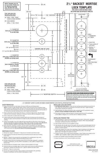
DOOR PREPRATION<br />
1) Draw a horizontal line on both sides of the door at 38" above the finished floor.<br />
NOTE: If mortise for strike already exists in frame, locate horizontal line for knob/lever using<br />
strike mortise as a reference point. Go down 1 7 8"<br />
from the center line of the strike and mark the<br />
horizontal line of the knob/lever at this point. Our standard horizontal center line for the strike is<br />
1 7 8"<br />
above the horizontal knob/lever line or 39 7 8"<br />
above the finished floor.<br />
2) Draw a vertical line on both sides of the door 2 ½" back from edge of door. This will be the<br />
center line for the turnpiece, cylinder(s), knob/lever, and thru-bolts for backplates or roses.<br />
3) Draw a vertical line on center of the door edge.<br />
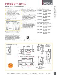
<strong>2½</strong>" <strong>BACKSET</strong> LEVER X LEVER OR KNOB X KNOB <strong>MORTISE</strong> <strong>LOCK</strong> INSTALLATION INSTRUCTIONS<br />
4) Locate vertical center line for strike by taking half the door thickness plus the thickness of<br />
silencers (if used). Use this dimension to locate the strike vertical center line from the doorstop<br />
molding.<br />
5) Position the template on the door edge with the horizontal line of the knob or lever lining up<br />
with the horizontal line marked on the door. Mark centers of holes for mortise cavity. Be sure to<br />
mark the clearance needed on both sides of the cavity for the anti-friction latch.<br />
6) Mark lever/knob, cylinder(s), turnpiece, and thru-bolts for backplates to be drilled (Refer to<br />
Diagram #2 on reverse side). If roses are being used, drill two ½" holes for thru-bolted roses<br />
next to lever/knob hole. Do not drill holes for thru-bolted backplates.<br />
MORTISING OF DOOR<br />
1) Mortise door edge for lockbody 3 ¾" deep and cut notches for anti-friction latch.<br />
2) Insert lockbody into cavity and outline the lock armored front and mark lock mounting<br />
screw holes.<br />
3) Mortise ¼" deep for the armored front and faceplate to be installed later. Also notch<br />
deeper or drill two cavities to allow the beveling screws to sit in.<br />
4) Drill pilot holes for the lock mounting screws and all of the holes needed for cylinder(s),<br />
turnpiece, knobs/levers, and thru-bolts for backplates or roses. (Refer to Diagram #2 on<br />
reverse side).<br />
5) Using faceplate as a template outline, mortise to allow faceplate to fit snugly.<br />
6) Using the strike as a template, align it on the marked center lines and outline strike and<br />
openings for deadbolt and latchbolt. Drill 1" deep for deadbolt and latch holes.<br />
7) Mortise 3<br />
32 " deep for mortise strike.<br />
[a] 2 7<br />
8 "<br />
[a] 2 7 8"<br />
[b] 2 716 "<br />
[b] 1 3 8 "<br />
1<br />
4"<br />
8) Drill all of the required diameter holes as stated on the template for the cylinder(s),<br />
turnpiece, knobs/levers, and thru-bolts for backplates or roses.<br />
[a]<br />
[b]<br />
CENTER LINE OF <strong>LOCK</strong><br />
[b]<br />
[a]<br />
2 1<br />
2"<br />
<strong>BACKSET</strong><br />
1½"<br />
FOR ROSES ONLY<br />
1 3<br />
16"<br />
2 7<br />
16 "<br />
3 ¾" <strong>MORTISE</strong> DEPTH<br />
7<br />
8 "<br />
6¼"<br />
7<br />
8 "<br />
1 7<br />
8 "<br />
3 5<br />
8 "<br />
¼"<br />
1½"<br />
INSTALLING <strong>LOCK</strong> AND STRIKE<br />
1) FOR BEVELED EDGE DOOR: Loosen the two beveling screws behind armored front of<br />
lock. Adjust the armored front of lockbody to the bevel of the door. Tighten beveling<br />
screws before installing the lockbody.<br />
2) Insert lockbody into cavity and secure to door using the two #12 combination screws.<br />
DO NOT ATTACH FINISHED FACEPLATE AT THIS TIME.<br />
3) Place strike into strike mortise and attach it to frame using the two #12 combination<br />
screws (Refer to Diagram #1 on reverse side for installation of strike).<br />
INSTALLING FINISHED TRIM<br />
1) Install backplates or roses with screws showing on the interior. At this point, just tighten<br />
the screws snugly to allow rose or backplates to be aligned. (When using backplates<br />
w/turnpiece, turnpiece should be on the interior.)<br />
2) Insert cylinder at this time, but only tighten by hand.<br />
3) Insert spindle with shoulder stop on the exterior. Be sure center of spindle aligns with the<br />
center of the lock. When shoulder stop sits flush against the outside hub of the lock, the<br />
spindle is properly aligned.<br />
4) Place nylon washers into holes of the roses/plates. Attach knobs/levers and tighten set<br />
screws. (Skip this step if lever/knob is already fastened to plate.) This will align<br />
plates/roses. Now tighten the plate/rose screws.<br />
5) Thread in cylinder until it is flush with the backplate or collar. Position the cylinder so the<br />
“OMNIA” logo is readable. Tighten cylinder set screw through the lock front.<br />
6) Attach lock faceplate using the faceplate screws provided.<br />
7) Adjust knobs/levers to turn freely and tighten set screws.<br />
R<br />
DOTTED LINE MUST BE PLACED ON DOOR EDGE<br />
<strong>2½</strong> " <strong>BACKSET</strong> <strong>MORTISE</strong><br />
<strong>LOCK</strong> <strong>TEMPLATE</strong><br />
4"<br />
FOR LEVER X LEVER OR KNOB X KNOB<br />
SEE OTHER SIDE FOR OPPOSITE <strong>TEMPLATE</strong><br />
3 "<br />
8<br />
38"<br />
DISTANCE<br />
TO FLOOR<br />
8"<br />
#12-24 FLATHEAD<br />
COMBINATION SCREWS<br />
CEDAR GROVE, NJ 07009<br />
<strong>LOCK</strong> FACE<br />
1¼"<br />
OMNIA INDUSTRIES, INC.<br />
3<br />
8"<br />
DRILL<br />
1" DIAMETER<br />
3¾" DEEP<br />
Insert lock<br />
Trace outline of<br />
lock front<br />
Mortise ¼"<br />
deep for<br />
armored front<br />
and faceplate<br />
CLEARANCE<br />
FOR<br />
ANTI-FRICTION<br />
LATCH<br />
3<br />
8"<br />
CAUTION: DOOR AND FRAME MANUFACTURERS<br />
When door gasketing or silencers are used, proper<br />
allowances must be made for strike location to maintain<br />
a common centerline with lock and door so that the bolt<br />
will freely enter strike.<br />
OI MNIA<br />
N D U S T R I E S , I N C .<br />
OM-LLKK25-00<br />
Rev. 12/29/10
<strong>2½</strong> " <strong>BACKSET</strong> <strong>MORTISE</strong><br />
<strong>LOCK</strong> <strong>TEMPLATE</strong><br />
Insert lock<br />
FOR LEVER X LEVER OR KNOB X KNOB<br />
SEE OTHER SIDE FOR OPPOSITE <strong>TEMPLATE</strong><br />
3<br />
8"<br />
DRILL<br />
1" DIAMETER<br />
3¾" DEEP<br />
Trace outline of<br />
lock front<br />
Mortise ¼"<br />
deep for<br />
armored front<br />
and faceplate<br />
CLEARANCE<br />
FOR<br />
ANTI-FRICTION<br />
LATCH<br />
3<br />
8"<br />
<strong>MORTISE</strong> STRIKE INSTALLATION INSTRUCTIONS<br />
1) Locate center line of strike by taking the center line of the mortise lock case and going up 3<br />
8"<br />
and making a line<br />
on the jamb.<br />
2) Position the center line of the strike onto the line and using the strike as a guide trace the edge of the strike.<br />
3) Mortise the jamb 3<br />
32"<br />
deep for the strike.<br />
4) When box strike is used a minimum of 1" mortise depth is needed.<br />
5) When box strike is not used be sure to mortise deep enough to allow the latchbolt and deadbolt to fully extend.<br />
4<br />
<strong>LOCK</strong> FACE<br />
7/8<br />
"<br />
1¼"<br />
DIAGRAM #1 DIAGRAM #2<br />
4<br />
1/8<br />
"<br />
1" MIN.<br />
"<br />
3 32<br />
8"<br />
#12-24 FLATHEAD<br />
COMBINATION SCREWS<br />
"<br />
5/8<br />
1¼"<br />
3 "<br />
8<br />
4"<br />
38"<br />
DISTANCE<br />
TO FLOOR<br />
OF STRIKE AND <strong>LOCK</strong> FRONT<br />
1"<br />
DOTTED LINE MUST BE PLACED ON DOOR EDGE<br />
¾"<br />
3<br />
3 /8<br />
"<br />
¾"<br />
¼"<br />
1½"<br />
1 7<br />
8 "<br />
3 5<br />
8 "<br />
7<br />
8 "<br />
6¼"<br />
7<br />
8 "<br />
BOX STRIKE<br />
2 1<br />
2"<br />
<strong>BACKSET</strong><br />
OF STRIKE<br />
"<br />
3 /8<br />
OF <strong>LOCK</strong><br />
1 3<br />
16"<br />
2 7<br />
16 "<br />
FOR ROSES ONLY<br />
1½"<br />
[a]<br />
[b]<br />
CENTER LINE OF <strong>LOCK</strong><br />
[b]<br />
[a]<br />
3 ¾" <strong>MORTISE</strong> DEPTH<br />
1<br />
4"<br />
FUNCTION HOLES TO DRILL<br />
A<br />
AC<br />
B<br />
CD<br />
E<br />
EW<br />
F<br />
Function<br />
FW<br />
J<br />
L<br />
N<br />
PD<br />
SD<br />
[b] 1 3 8 "<br />
Cyl. Hole<br />
outside<br />
X<br />
X<br />
X<br />
X<br />
X<br />
[a] 2 7 8"<br />
[b] 2 716 "<br />
Cyl. Hole<br />
2 sides<br />
Turnpiece<br />
inside<br />
X<br />
X X<br />
X<br />
X<br />
Knob hole<br />
2 sides<br />
X C<br />
X X C<br />
X X X C<br />
Both<br />
Sides<br />
[a] 2 7<br />
8 "<br />
X<br />
X<br />
X<br />
X<br />
X X<br />
X<br />
X<br />
Cam type<br />
S<br />
S<br />
C<br />
C<br />
S<br />
Key: C = Cloverleaf S=Straight Cam<br />
NOTE: Template may not<br />
be true-to-size. Please use<br />
for reference purposes<br />
only. DO NOT drill until<br />
measurements are verified.<br />
FOR THRU-BOLTED<br />
BACKPLATES ONLY<br />
[a] 3000, 11000, 12000,<br />
24000 & 25000 SERIES<br />
[b] 4000 SERIES<br />
DRILL ½" DIA. HOLE<br />
1¼" DIAMETER<br />
Drill only if CYLINDER<br />
is on this side<br />
5<br />
8 " DIAMETER<br />
Drill only if TURNPIECE<br />
is on this side<br />
of strike<br />
( " up from of lock)<br />
3 8<br />
of lock<br />
(1½" up from of knob/lever)<br />
½" DIAMETER<br />
Drill only if THRU-BOLTED<br />
ROSES are being used<br />
¾" DIAMETER<br />
Drill only if KNOB or LEVER<br />
is on this side<br />
½" DIAMETER<br />
Drill only if THRU-BOLTED<br />
ROSES are being used<br />
FOR THRU-BOLTED<br />
BACKPLATES ONLY<br />
[b] 4000 SERIES<br />
[a] 3000, 11000, 12000,<br />
24000 & 25000 SERIES<br />
DRILL ½" DIA. HOLE<br />
OI MNIA<br />
N D U S T R I E S , I N C .<br />
CEDAR GROVE<br />
NJ 07009<br />
OM-LLKK25-00<br />
R<br />
Rev. 12/29/10