6000 Series Electric Strike Spring Kit PARTS LIST - Von Duprin
6000 Series Electric Strike Spring Kit PARTS LIST - Von Duprin
6000 Series Electric Strike Spring Kit PARTS LIST - Von Duprin

Create successful ePaper yourself
Turn your PDF publications into a flip-book with our unique Google optimized e-Paper software.
VON DUPRIN ®<br />
Installation Instructions<br />
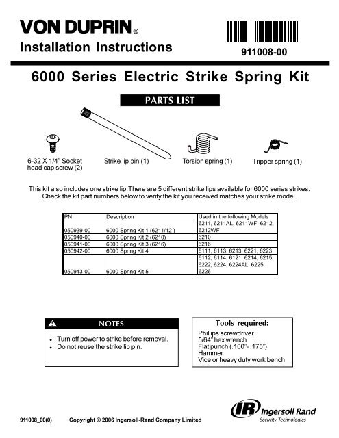
<strong>6000</strong> <strong>Series</strong> <strong>Electric</strong> <strong>Strike</strong> <strong>Spring</strong> <strong>Kit</strong><br />
6-32 X 1/4” Socket<br />
head cap screw (2)<br />
911008_00(0)<br />
<strong>Strike</strong> lip pin (1)<br />
911008-00(0)<br />
PREPUBLICATION<br />
REVIEW COPY REV A<br />
<strong>PARTS</strong> <strong>LIST</strong><br />
Copyright © 2006 Ingersoll-Rand Company Limited<br />
Torsion spring (1)<br />
911008-00<br />
PN Description Used in the following Models<br />
6211, 6211AL, 6211WF, 6212,<br />
050939-00 <strong>6000</strong> <strong>Spring</strong> <strong>Kit</strong> 1 (6211/12 ) 6212WF<br />
050940-00 <strong>6000</strong> <strong>Spring</strong> <strong>Kit</strong> 2 (6210) 6210<br />
050941-00 <strong>6000</strong> <strong>Spring</strong> <strong>Kit</strong> 3 (6216) 6216<br />
050942-00 <strong>6000</strong> <strong>Spring</strong> <strong>Kit</strong> 4 6111, 6113, 6213, 6221, 6223<br />
6112, 6114, 6121, 6214, 6215,<br />
6222, 6224, 6224AL, 6225,<br />
050943-00 <strong>6000</strong> <strong>Spring</strong> <strong>Kit</strong> 5<br />
6226<br />
Tripper spring (1)<br />
This kit also includes one strike lipThere are 5 different strike lips available for <strong>6000</strong> series strikes<br />
Check the kit part numbers below to verify the kit you received matches your strike model<br />
!<br />
NOTES<br />
l Turn off power to strike before removal<br />
l Do not reuse the strike lip pin<br />
Tools required:<br />
Phillips screwdriver<br />
5/64” hex wrench<br />
Flat punch (100”- 175”)<br />
Hammer<br />
Vice or heavy duty work bench
1<br />
Solenoid<br />
plug<br />
<strong>Strike</strong> box<br />
Figure 1-1<br />
<strong>Strike</strong> box<br />
screws<br />
INSTALLATION<br />
Remove strike and strike box<br />
See Figure 1-1<br />
11 Remove strike mounting screws and<br />
remove strike assembly from frame<br />
12 Unplug solenoid<br />
13 Remove strike box screws using phillips<br />
screwdriver and remove strike box<br />
from faceplate<br />
Configuration of<br />
faceplate and strike box<br />
may vary from illustration<br />
Faceplate<br />
Mounting<br />
screws<br />
Remove strike box cover and plug<br />
See Figure 2-1<br />
21 Using 5/64” hex wrench, remove two<br />
socket head screws and remove strike<br />
box cover<br />
22 Remove black hole plug if present<br />
<strong>Strike</strong> box<br />
cover<br />
Socket<br />
head<br />
screws (2)<br />
Figure 2-1<br />
Black<br />
hole plug<br />
Page 2 of 4 911008_00(0)<br />
2
3<br />
Torsion<br />
spring<br />
Remove strike lip pin, spring(s),<br />
and switch (if present)<br />
See Figure 3-1<br />
31 Slide switch off box (if present)<br />
32 Observe the strike lip pin currently<br />
in strike box and find rounded end<br />
33 Place strike box on vice or heavy<br />
duty work bench as shown with<br />
rounded end of pin up<br />
34 Using a flat punch (100” to 175”<br />
diameter) hammer pin out of<br />
strike box<br />
35 Remove torsion spring and tripper<br />
spring (if present)<br />
36 Remove and discard existing strike lip<br />
Flat punch<br />
<strong>Strike</strong> lip<br />
Tripper<br />
spring<br />
911008_00(0)<br />
!<br />
Figure 3-1<br />
NOTE<br />
Old strike lip pin must not<br />
be reused because it will<br />
have grooves worn into it<br />
<strong>Strike</strong> box<br />
assembly<br />
<strong>Strike</strong> lip pin<br />
Rounded end<br />
must be up<br />
Switch<br />
4<br />
Install new strike lip, torsion spring, and pin<br />
See Figure 4-1<br />
41 Flip strike box over and align new strike lip<br />
42 Align new spring in strike lip groove as shown<br />
43 Slide new strike lip pin into strike box in same<br />
direction of old pin with rounded end down<br />
New torsion<br />
spring<br />
Hook on spring<br />
must fit in groove<br />
in strike lip<br />
5<br />
Figure 4-1<br />
New strike<br />
lip pin<br />
New strike lip<br />
Install tripper spring (for DS strikes only)<br />
See Figure 5-1<br />
51 Align hooked end of new spring in tripper<br />
groove as shown<br />
52 Slide new strike lip pin through<br />
strike lip and tripper<br />
<strong>Strike</strong> lip<br />
Figure 5-1<br />
Tripper<br />
Tripper<br />
spring<br />
Hook on spring<br />
must fit in groove<br />
in tripper<br />
Page 3 of 4
6<br />
7<br />
Switch<br />
Slider<br />
Secure new pin<br />
See Figure 6-1<br />
61 Using flat punch and hammer, drive pin until<br />
flush with strike box surface<br />
62 Verify pin is secure by pressing flat punch<br />
against rounded end of pin by hand<br />
If pin moves, remove and repeat steps 4-6<br />
installing pin from opposite end of box<br />
Reinstall switch (if present)<br />
See Figure 7-1<br />
71 Rotate strike lip and tripper to closed<br />
position as shown (slider may need<br />
to slide down temporarily)<br />
72 Slide switch back onto box<br />
73 Verify switch actuator is in correct<br />
position and keep strike lip in closed<br />
position <br />
Figure 7-1<br />
8<br />
Switch actuator<br />
Actuator must be<br />
positioned as shown<br />
If tripper and strike lip<br />
are allowed to rotate<br />
to open position,<br />
switch lever can<br />
become lodged<br />
behind tripper<br />
Flush to<br />
surface<br />
Figure 6-1<br />
Reassemble strike<br />
See Figure 8-1<br />
81 Place strike box cover onto box (ensure<br />
spring tip is inside box cover)<br />
82 Secure strike box cover with two socket<br />
head screws using 5/64” hex wrench<br />
83 Replace black hole plug if present<br />
Rotate strike lip by hand and verify that it<br />
opens and returns fully without binding<br />
(Fail secure strikes must be energized)<br />
84 Reinstall box into faceplate<br />
85 Plug in solenoid<br />
86 Reinstall strike into door frame and secure<br />
with mounting screws<br />
Refer to strike installation instructions if<br />
necessary during reinstallation<br />
<strong>Strike</strong> box<br />
cover<br />
Socket<br />
head<br />
screws (2)<br />
<strong>Spring</strong> tip must be<br />
inside box cover<br />
Figure 8-1<br />
Hook on spring<br />
must fit in groove<br />
in strike lip<br />
Black<br />
hole plug<br />
Page 4 of 4 911008_00(0)