Electromagnetic Lock Installation Instruction - door entry systems
Electromagnetic Lock Installation Instruction - door entry systems
Electromagnetic Lock Installation Instruction - door entry systems

You also want an ePaper? Increase the reach of your titles
YUMPU automatically turns print PDFs into web optimized ePapers that Google loves.
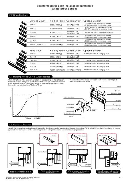
Specifications<br />
Holding Force Curve & Accessories<br />
Optional Bracket<br />
Regular <strong>Installation</strong><br />
<strong>Electromagnetic</strong> <strong>Lock</strong> <strong>Installation</strong> <strong>Instruction</strong><br />
(Waterproof Series)<br />
Surface Mount Holding Force Current Draw Optional Bracket<br />
10003S<br />
10001ST<br />
GL-600S<br />
10006S<br />
EM-750<br />
10010ST,10020ST<br />
Out-swinging<br />
600 lbs(272 Kg)<br />
600 lbs (272 Kg)<br />
800 lbs (363 Kg)<br />
800 lbs (363 Kg)<br />
1200 lbs(545 Kg)<br />
The holding force of the electromagnetic lock is depending on the voltage of<br />
the power supply. The graph below illustrates the change of the holding force<br />
under different voltage. The holding forces of the electromagnetic lock used<br />
here by the manufacture here "Colinear" force.<br />
Holding force<br />
With L-bracket for narrow<br />
<strong>door</strong> frames<br />
300mA@12VDC<br />
280mA@12VDC<br />
500mA@12VDC<br />
250mA@24VDC<br />
340mA@12VDC<br />
340mA@12VDC<br />
460mA@12VDC<br />
Frameless<br />
Glass Door<br />
With U-bracket for frameless<br />
glass <strong>door</strong> leaf<br />
L-150 bracket for narrow <strong>door</strong> frames.<br />
LZ-150 bracket for in-swinging <strong>door</strong>s.<br />
L-01ST bracket for narrow <strong>door</strong> frames.<br />
LZ-01ST bracket for in-swinging <strong>door</strong>s.<br />
L-GL600 bracket for narrow <strong>door</strong> frames.<br />
L-400 bracket for narrow <strong>door</strong> frames.<br />
LZ-400 bracket for in-swinging <strong>door</strong>s.<br />
L-750 bracket for narrow <strong>door</strong> frames.<br />
LZ-750 bracket for in-swinging <strong>door</strong>s.<br />
L-600 bracket for narrow <strong>door</strong> frames.<br />
LZ-600 bracket for in-swinging <strong>door</strong>s.<br />
Please note that the actual accessory pack varies according to the<br />
electromagnetic lock model.<br />
Blind Nut<br />
Mounting Plate<br />
In-swinging<br />
With LZ-bracket or Z-bracket<br />
for in-swinging <strong>door</strong> frames<br />
Cable<br />
Magnet<br />
Fixing screw<br />
Anti-tamper Cap<br />
Identify the <strong>door</strong> swinging direction and inspect the <strong>door</strong> frame header to determine if bracket is required. A L- bracket, LZ-bracket, Z-bracket or U-bracket<br />
(optional) may be required for the electromagnet depending on the frame header and swinging direction.<br />
Out-swinging<br />
300 lbs(136 Kg)<br />
Face Mount Holding Force Current Draw Optional Bracket<br />
10003F<br />
GL-600F<br />
EM-750-1<br />
GL-850<br />
GL-1200<br />
DGL-2400<br />
Voltage (12 VDC)<br />
Copyright Gianni Industries, Inc. All Rights Reserved.<br />
P-MU-WP-EM Ver. B Publish:2004.10.18<br />
Narrow frame<br />
300 lbs(136 Kg)<br />
600 lbs (272 Kg)<br />
800 lbs (363 Kg)<br />
800 lbs (363 Kg)<br />
1200 lbs(545 Kg)<br />
1200 lbs(545 Kg)X2<br />
" L " Bracket<br />
300mA@12VDC<br />
500mA@12VDC<br />
250mA@24VDC<br />
340mA@12VDC<br />
340mA@12VDC<br />
460mA@12VDC<br />
460mA@12VDCX2<br />
Armature screw<br />
Guide Pins<br />
Door spacer<br />
Sexnut Bolt<br />
Rubber Washer<br />
Washer<br />
Out-swinging<br />
UBK Bracket<br />
Z-150 bracket for in-swinging <strong>door</strong>.<br />
Z-750 bracket for in-swinging <strong>door</strong>.<br />
Z-400 bracket for in-swinging <strong>door</strong>.<br />
Z-600 bracket for in-swinging <strong>door</strong>.<br />
Z-600 bracket for in-swinging <strong>door</strong>.<br />
Armature<br />
Plate<br />
" L Z " Bracket<br />
4-1
Regular <strong>Installation</strong><br />
4<br />
<strong>Installation</strong> Steps<br />
1<br />
Template<br />
Fold the mounting template along the<br />
dotted line to a 90-degree angle.<br />
Drill and tap holes as indicated. Insert two Blind Nuts into<br />
separate holes, one for<br />
each fixing screw.<br />
5 6<br />
Use the screws to permanently mount the<br />
mounting plate, mount the magnet with<br />
hardware provided.<br />
7<br />
Make sure the Guide Pins are in the two<br />
guide pin holes.<br />
8<br />
2<br />
Out-swinging<br />
9.4mm holes for M6 Blind Nuts.<br />
7mm holes for M5 Blind Nuts.<br />
<strong>door</strong><br />
Template<br />
Close the <strong>door</strong>, find a mounting location<br />
on the <strong>door</strong> frame near the upper freemoving<br />
corner of the <strong>door</strong>, as close to the<br />
corner of the <strong>door</strong> frame as possible.<br />
9<br />
Use the allen wrench. To<br />
slowly tighten the Blind Nut.<br />
(Don't turning over)<br />
3<br />
Place the template against the <strong>door</strong> and<br />
frame. Be sure the centerline of the armature<br />
template matches the centerline of the<br />
magnet template.<br />
This compress the Blind<br />
Nut so that it remains<br />
permanently fixed in the<br />
frame.<br />
10<br />
Connect the power lead, and test the unit.<br />
Close the <strong>door</strong> ,use the Allen wrench or<br />
add washers to adjust the gap of Armature<br />
plate and the magnet.<br />
Finish<br />
With L bracket for narrow <strong>door</strong> frames With U bracket for frameless glass <strong>door</strong>s<br />
L bracket is used as extension on narrow <strong>door</strong> frames to<br />
provide adequate mounting surface.<br />
" L " Bracket<br />
Out-swinging<br />
Fixing screw<br />
Guide Pins<br />
(Option)<br />
Copyright Gianni Industries, Inc. All Rights Reserved.<br />
P-MU-WP-EM Ver. B Publish:2004.10.18<br />
Armature Plate<br />
Mounting the armature plate to<br />
the <strong>door</strong> . Actual installation<br />
varies according to <strong>door</strong> style.<br />
Put one rubber washer between two<br />
washers, and place them over the<br />
armature screw between the armature<br />
plate and the <strong>door</strong>.<br />
L-150 for 10003S<br />
L-01ST for 10001ST<br />
L-GL600 for GL-600S<br />
L-400 for 10006S<br />
L-750 for EM-750<br />
L-600 for 10010ST,10020ST<br />
Blind Nuts<br />
Tool<br />
Universal glass <strong>door</strong> kits are compatible with lock models,<br />
except 1200 lbs serial.<br />
Out-swinging<br />
allen wrench<br />
Hollow Metal Door Solid Door Reinforced Door<br />
16mm 8mm 12.7mm 8mm<br />
Drill an 8 mm hole through<br />
<strong>door</strong>, from sexnut bolt side<br />
only, enlarge the 8mm hole<br />
to 16mm.<br />
Rubber Washer<br />
This will allow the armature plate to<br />
pivot slightly around the armature<br />
screw in order to compensate for<br />
<strong>door</strong> misalignment.<br />
Insert the anti-tamper caps<br />
into the mounting screw access<br />
holes. This should be the last<br />
step, as once the tamper caps are<br />
in place, they will be difficult to<br />
remove.<br />
36mm<br />
Drill an 8 mm hole thru<br />
<strong>door</strong> from sexnut bolt<br />
side of <strong>door</strong>, drill 12.7mm<br />
hole, 36mm in depth.<br />
(Option)<br />
UBK Bracket<br />
Remove the tool.<br />
6.8mm for M8-1.25 thread<br />
Drill an 6.8 mm dia.<br />
Hole and tap for<br />
M8x12.5 thread.<br />
UBK-008 for 8mm of glass <strong>door</strong><br />
UBK-010 for 10mm of glass <strong>door</strong><br />
UBK-012 for 12mm of glass <strong>door</strong><br />
UBK-014 for 14mm of glass <strong>door</strong><br />
4-2
With LZ bracket or Z brack for In-swinging <strong>door</strong>s<br />
In-swinging<br />
" L Z " Bracket " Z " Bracket<br />
(Option) (Option)<br />
In-swinging<br />
<strong>Installation</strong> Steps of LZ or Z bracket for In-swinging <strong>door</strong>s<br />
1<br />
Find a mounting location on the<br />
<strong>door</strong> frame for the L bracket. Make<br />
sure that the <strong>door</strong> is still closeable.<br />
5<br />
Put one rubber washer between<br />
armature plate and the Z bracket,<br />
and place them over the 8mm<br />
armature screw.<br />
Connecting Diagram<br />
2C Wire Leads:<br />
Single Voltage Input<br />
12 VDC: Black, Red<br />
Control Device<br />
N.C. contact or Access Relay<br />
Black<br />
Red<br />
24 VDC: Black, White<br />
-<br />
+<br />
Control Device<br />
N.C. contact or Access Relay<br />
Black<br />
White<br />
-<br />
+<br />
Power<br />
supply<br />
Power<br />
supply<br />
2<br />
X<br />
Tighten the electromagnetic lock<br />
on the L bracket by using the<br />
fixing screw.(For the models with<br />
Face Mount, the Emlock can be<br />
mounted directly on the <strong>door</strong> frame)<br />
6<br />
Close the <strong>door</strong>. Measure the correct<br />
position by bringing the armature<br />
plate close to the contact surface of<br />
the electromagnetic lock.<br />
Red<br />
White<br />
Black<br />
Green<br />
Red<br />
White<br />
Black<br />
Green<br />
4C Wire Leads:<br />
Dual voltage<br />
Power<br />
supply<br />
Power<br />
supply<br />
+<br />
3<br />
X<br />
Power<br />
In-swinging<br />
Assemble the Z bracket, and make<br />
sure that the Z bracket is adjustable.<br />
7 Finish<br />
5C Wire Leads:<br />
Monitoring Output<br />
LZ-Bracket<br />
LZ-150<br />
LZ-01ST<br />
LZ-GL600<br />
LZ-750<br />
LZ-400<br />
LZ-600<br />
Z-Bracket<br />
Z-150<br />
Z-GL600<br />
Z-750<br />
Z-400<br />
Z-600<br />
4<br />
10003S<br />
10001ST<br />
Application<br />
Application X Value<br />
10003F 32mm<br />
Insert the guide pins into the<br />
armature plate. The guide pins<br />
will prevent the armature plate to<br />
pivot around.<br />
Once the position is correct,<br />
use the screws to permanently<br />
mount the Z bracket on the <strong>door</strong><br />
frame. This should be the last step.<br />
6C Wire Leads:<br />
Dual voltage and<br />
Monitoring Output<br />
+<br />
-<br />
+<br />
+<br />
+<br />
-<br />
-<br />
-<br />
White:N.C.<br />
Black:COM.<br />
Red:N.O.<br />
Blue<br />
Blue Control Device<br />
N.C. contact or<br />
Access Relay<br />
(Power input is polarity free) (Power input is polarity free) (Power input is polarity free) (Power input is polarity free)<br />
Copyright Gianni Industries, Inc. All Rights Reserved.<br />
P-MU-WP-EM Ver. B Publish:2004.10.18<br />
Face Mount<br />
Surface Mount<br />
Voltage Selection: 12 VDC<br />
Control Device<br />
N.C. contact or Access Relay<br />
Voltage Selection: 24 VDC<br />
Control Device<br />
N.C. contact or Access Relay<br />
Turn on the power of EM-<strong>Lock</strong>,<br />
and let the armature plate bonds<br />
to the EM-lock. Adjust the position<br />
between the Z bracket and the<br />
<strong>door</strong> frame.<br />
Magnet bond sensor output<br />
, remotely monitors the<br />
<strong>door</strong> lock/unlock status.<br />
(Rating: 0.25A@12VDC)<br />
-<br />
The "X" value in the table below for each<br />
bracket to mount on the <strong>door</strong> frame,<br />
shows the minimum requirement width of<br />
the <strong>door</strong> frame for different electromagnetic<br />
lock model.<br />
Power<br />
supply<br />
GL-600S<br />
X Value<br />
37mm<br />
48mm<br />
50mm<br />
48mm<br />
48mm<br />
76mm<br />
44mm<br />
45mm<br />
45mm<br />
62mm<br />
EM-750,EM-750-2<br />
10006S<br />
10010ST,10020ST<br />
GL-600F<br />
EM-750-1,EM-750-2<br />
GL-850<br />
GL-1200F,DGL-2400<br />
Voltage Selection: 12 VDC<br />
Red<br />
White<br />
Voltage Selection: 24 VDC<br />
Red<br />
White<br />
Black<br />
Green<br />
Power<br />
supply<br />
Black<br />
Green<br />
Control Device<br />
Blue: Com. N.C. Contact<br />
Yellow: N.O. Magnet bond<br />
sensor output<br />
Blue: Com.<br />
Yellow: N.O.<br />
Power<br />
supply<br />
Control Device<br />
N.C. Contact<br />
Magnet bond<br />
sensor output<br />
4-3
Important Notes<br />
During the installation procedure, it<br />
is important to make sure that the<br />
working direction of the armature<br />
plate has to be facing toward the<br />
contact surface of the electromagnetic<br />
lock intend to have the maximum<br />
holding force.<br />
The contact surface of the<br />
electromagnetic lock and the armature<br />
plate has to be completely attached;<br />
otherwise, the reed, which located in<br />
side the electromagnetic lock, will not<br />
be detected. It will result an incorrect<br />
output message for the bond sensor.<br />
Distance in feet from power source to farthest locking device<br />
Minimum<br />
Wire Gauge<br />
for12VDC<br />
Minimum<br />
Wire Gauge<br />
for24VDC<br />
Trouble Shooting<br />
Problem Possible Cause Solution<br />
Door does not lock No power<br />
Reduced holding force<br />
Sensor output is not functioning<br />
Reed<br />
Copyright Gianni Industries, Inc. All Rights Reserved.<br />
P-MU-WP-EM Ver. B Publish:2004.10.18<br />
In-swinging<br />
Be aware that it is better to install<br />
the electromagnet lock inside the<br />
house and hide the cable inside the<br />
<strong>door</strong> frame in order to against the<br />
unlawful <strong>entry</strong>.<br />
Damage to the mating surfaces may<br />
reduce the efficiency of the lock and<br />
cause rust.<br />
Poor contact between electromagnet and<br />
armature plate<br />
Low voltage or incorrect voltage setting<br />
A secondary diode was installed across<br />
the electromagnet<br />
Misalignment between the reed switch<br />
and its magnet<br />
Power<br />
Input<br />
UPS<br />
Control<br />
Device<br />
The electromagnetic locks are failsafe<br />
and will require a power supply<br />
equipped with battery back up when<br />
power outages may interfere with<br />
desired security.<br />
Apply a light coat of a silicon<br />
lubricant to prevent rust. Wipe<br />
away the excess.<br />
Check to make sure the wires are securely tightened to the correct terminal block<br />
Check that the power supply is connected and operating properly<br />
Make sure the lock switch is wired correctly<br />
Make sure the lock switch is wired correctly.<br />
Power<br />
Make sure the electromagnet and armature plate are properly aligned<br />
Make sure the contact surfaces of the electromagnet and armature plate are clean<br />
and free from dust<br />
Ensure the electromagnetic lock is set for the correct voltage.<br />
Check for proper voltage at the electromagnetic locks input. If low, determine if the<br />
correct wire gauge is being used to prevent excessive voltage drop.<br />
Remove any diode installed across the magnet for "spike"<br />
suppression. (The magnet is fitted with a metal oxide varistor to prevent back EMF)<br />
+<br />
-<br />
Check the installation of armature with supplied template.<br />
+<br />
-<br />
Do not install a diode in parallel<br />
with any magnetic lock. A diode<br />
will cause a delay when releasing<br />
the <strong>door</strong> and residual magnet to occur.<br />
+<br />
-<br />
N.O.<br />
COM.<br />
N.C.<br />
Power<br />
Input<br />
SPDT relay<br />
3A@12VDC<br />
Do not run power wires and signal<br />
wire in the same cable or conduit.<br />
4-4