Screen Sizes Impact on Picture and Sound - Dolby Laboratories Inc.
Screen Sizes Impact on Picture and Sound - Dolby Laboratories Inc.
Screen Sizes Impact on Picture and Sound - Dolby Laboratories Inc.

You also want an ePaper? Increase the reach of your titles
YUMPU automatically turns print PDFs into web optimized ePapers that Google loves.
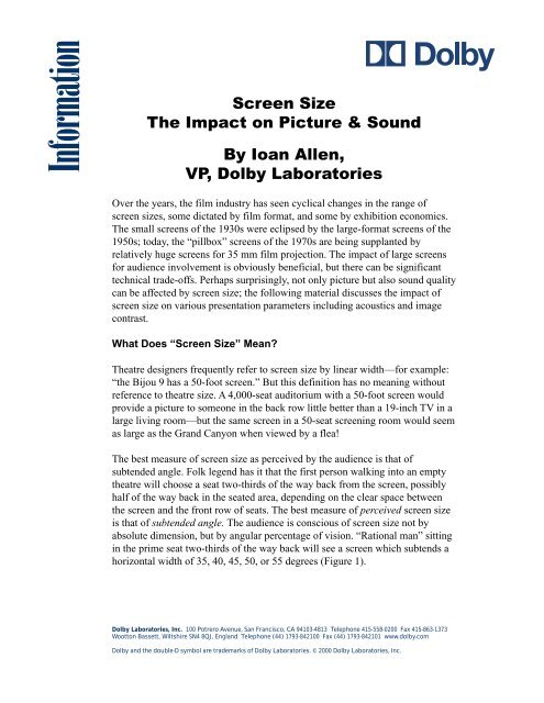
Informati<strong>on</strong><br />
<str<strong>on</strong>g>Screen</str<strong>on</strong>g> Size<br />
The <str<strong>on</strong>g>Impact</str<strong>on</strong>g> <strong>on</strong> <strong>Picture</strong> & <strong>Sound</strong><br />
By Ioan Allen,<br />
VP, <strong>Dolby</strong> <strong>Laboratories</strong><br />
Over the years, the film industry has seen cyclical changes in the range of<br />
screen sizes, some dictated by film format, <strong>and</strong> some by exhibiti<strong>on</strong> ec<strong>on</strong>omics.<br />
The small screens of the 1930s were eclipsed by the large-format screens of the<br />
1950s; today, the “pillbox” screens of the 1970s are being supplanted by<br />
relatively huge screens for 35 mm film projecti<strong>on</strong>. The impact of large screens<br />
for audience involvement is obviously beneficial, but there can be significant<br />
technical trade-offs. Perhaps surprisingly, not <strong>on</strong>ly picture but also sound quality<br />
can be affected by screen size; the following material discusses the impact of<br />
screen size <strong>on</strong> various presentati<strong>on</strong> parameters including acoustics <strong>and</strong> image<br />
c<strong>on</strong>trast.<br />
What Does “<str<strong>on</strong>g>Screen</str<strong>on</strong>g> Size” Mean?<br />
Theatre designers frequently refer to screen size by linear width—for example:<br />
“the Bijou 9 has a 50-foot screen.” But this definiti<strong>on</strong> has no meaning without<br />
reference to theatre size. A 4,000-seat auditorium with a 50-foot screen would<br />
provide a picture to some<strong>on</strong>e in the back row little better than a 19-inch TV in a<br />
large living room—but the same screen in a 50-seat screening room would seem<br />
as large as the Gr<strong>and</strong> Cany<strong>on</strong> when viewed by a flea!<br />
The best measure of screen size as perceived by the audience is that of<br />
subtended angle. Folk legend has it that the first pers<strong>on</strong> walking into an empty<br />
theatre will choose a seat two-thirds of the way back from the screen, possibly<br />
half of the way back in the seated area, depending <strong>on</strong> the clear space between<br />
the screen <strong>and</strong> the fr<strong>on</strong>t row of seats. The best measure of perceived screen size<br />
is that of subtended angle. The audience is c<strong>on</strong>scious of screen size not by<br />
absolute dimensi<strong>on</strong>, but by angular percentage of visi<strong>on</strong>. “Rati<strong>on</strong>al man” sitting<br />
in the prime seat two-thirds of the way back will see a screen which subtends a<br />
horiz<strong>on</strong>tal width of 35, 40, 45, 50, or 55 degrees (Figure 1).<br />
<strong>Dolby</strong> <strong>Laboratories</strong>, <strong>Inc</strong>. 100 Potrero Avenue, San Francisco, CA 94103-4813 Teleph<strong>on</strong>e 415-558-0200 Fax 415-863-1373<br />
Woott<strong>on</strong> Bassett, Wiltshire SN4 8QJ, Engl<strong>and</strong> Teleph<strong>on</strong>e (44) 1793-842100 Fax (44) 1793-842101 www.dolby.com<br />
<strong>Dolby</strong> <strong>and</strong> the double-D symbol are trademarks of <strong>Dolby</strong> <strong>Laboratories</strong>. © 2000 <strong>Dolby</strong> <strong>Laboratories</strong>, <strong>Inc</strong>.
<str<strong>on</strong>g>Screen</str<strong>on</strong>g><br />
60º<br />
45º<br />
30º<br />
Prime Seat<br />
Rear Wall<br />
Figure 1: Subtended screen angles<br />
From a projector’s point of view, the most obvious significance of increased<br />
screen size is the need for more projecti<strong>on</strong> illuminati<strong>on</strong>, if the st<strong>and</strong>ard 16<br />
foot-lambert illuminati<strong>on</strong> is to be maintained; the implicati<strong>on</strong>s of this will be<br />
discussed further.<br />
First-Order Effects<br />
There are obvious relati<strong>on</strong>ships between subtended screen angle <strong>and</strong> the<br />
filmgoer’s experience. As the screen angle gets larger, the story impact gets<br />
greater (Figure 2)—the audience feels less like TV watchers, <strong>and</strong> more like<br />
participants in the acti<strong>on</strong> <strong>on</strong> the screen. The eye’s theoretical field-of-view is<br />
110 degrees—a movie screen subtending such an angle is hard to ignore! All the<br />
c<strong>on</strong>necti<strong>on</strong>s between eye <strong>and</strong> brain are derived from the film, <strong>and</strong> the observer<br />
is potentially completely involved in the film.<br />
2
Very<br />
Involving<br />
Not<br />
Involving<br />
<strong>Picture</strong> Involvement<br />
Narrow<br />
Wide<br />
<str<strong>on</strong>g>Screen</str<strong>on</strong>g> Angle<br />
Figure 2: Subtended screen angle <strong>and</strong> picture involvement<br />
But as the perceived picture size increases, so do the picture flaws become more<br />
apparent, whether we are looking at film or TV (Figure 3). As a TV image is<br />
blown up, the flaws become glaringly apparent—the line structure, lack of<br />
definiti<strong>on</strong>, c<strong>on</strong>vergence problems, etc. A TV image (even from HDTV) is far<br />
inferior to 35 mm film, but even film has technical flaws when the picture is<br />
examined closely, or indeed, blown up too large.<br />
Good<br />
Bad<br />
Projecti<strong>on</strong> Involvement<br />
Narrow<br />
<str<strong>on</strong>g>Screen</str<strong>on</strong>g> Angle<br />
Figure 3: <str<strong>on</strong>g>Screen</str<strong>on</strong>g> angles <strong>and</strong> picture flaws<br />
3<br />
Wide
There are three most obvious problems visible when a film image is examined<br />
closely, or blown up large, as <strong>on</strong> an excessively big screen. The first is the grain,<br />
which can be paralleled with the line structure of a TV image. Even though<br />
camera negative stock, interpositive <strong>and</strong> internegative stocks, <strong>and</strong> release print<br />
stocks have been improved over the years, granularity is still visible, <strong>and</strong> the<br />
greater the enlargement (or subtended picture angle), the more visible the grain<br />
will become.<br />
Next, the film in a projector gate is never held perfectly steady. Jump (vertical<br />
irregularities) <strong>and</strong> weave (horiz<strong>on</strong>tal irregularities) seem unavoidable in<br />
c<strong>on</strong>venti<strong>on</strong>al 35 mm projecti<strong>on</strong>, <strong>and</strong> the greater the subtended screen angle, the<br />
more obvious the unsteadiness. Furthermore with a steady projector, image<br />
unsteadiness can be caused in the laboratory printer or during the generati<strong>on</strong>al<br />
process—sometimes clearly visible, with titles superimposed over static images.<br />
Again, the greater the enlargement, the more apparent the unsteadiness.<br />
The third result of increased subtended screen size is the difficulty of<br />
maintaining focus. The problem at first seems not to be so much that of<br />
maintaining focus, but more that the increased subtended screen size makes soft<br />
focus more obvious.<br />
So, as the perceived screen size increases, first-order effects lead to several<br />
apparent picture flaws. Too large a picture leads to excessive grain visibility,<br />
picture jump <strong>and</strong> weave visibility, <strong>and</strong> soft focus.<br />
Now, c<strong>on</strong>sider the effect of an increased screen size <strong>on</strong> the dem<strong>and</strong> for<br />
illuminati<strong>on</strong>. If the same illuminati<strong>on</strong> at the screen is to be maintained,<br />
increasing screen size (<strong>and</strong> c<strong>on</strong>sequently illuminated area) will dem<strong>and</strong><br />
increasing lamp power. As this lamp power is increased, the heat at the film<br />
plane will also increase. Two problems result: first, the film will flex in the film<br />
gate, making accurate focus more difficult to achieve, <strong>and</strong> sec<strong>on</strong>d, the heat may<br />
cause permanent deformati<strong>on</strong> of the film, resulting in the impossibility of ever<br />
achieving precise focus over the entire film field.<br />
An ideal screen size?<br />
The varying compromise between screen size (subtended angle) <strong>and</strong> picture<br />
quality has been <strong>on</strong>going for as l<strong>on</strong>g as there have been movies. Back in 1953,<br />
Twentieth Century Fox introduced Cinemascope 1<br />
. The wider aspect ratio<br />
(originally 2.55:1, then 2.35:1, <strong>and</strong> now st<strong>and</strong>ardized as 2.39:1) obviously<br />
provided a significantly greater picture involvement than a 1.33:1 image at the<br />
same height. But Fox evaluated the ideal subtended screen angle as 45 degrees 2<br />
,<br />
as this proved to be the point where the subjective curve of image involvement<br />
crossed the curve of visual technical flaws (Figure 4).<br />
4
Very<br />
Involving<br />
Not<br />
Involving<br />
<strong>Picture</strong> Involvement<br />
Quality Improvements<br />
30º<br />
5<br />
45º<br />
<str<strong>on</strong>g>Screen</str<strong>on</strong>g> Size<br />
INVOLVEMENT<br />
QUALITY<br />
Figure 4: Optimum “screen size”–1953 Cinemascope<br />
There is no doubt that some issues relating to film performance have improved<br />
since 1953. Release print stock, in particular, now has much finer grain than 40<br />
years ago. On the other h<strong>and</strong>, jump <strong>and</strong> weave in many modern projectors are<br />
probably no better than they used to be—<strong>and</strong> the lack of permanent<br />
projecti<strong>on</strong>ists assigned to each screen means that focus is less accurately<br />
maintained than used to be the case. It probably would be optimistic to think<br />
that the optimum screen angle for Cinemascope has progressed much above 45<br />
degrees. Perhaps the same evaluati<strong>on</strong> carried out today would lead to a number<br />
no greater than 50 degrees.<br />
1.85 v Scope<br />
The 1.85:1 aspect ratio is extremely inefficient, in that approximately 35 percent<br />
of the film frame area is thrown away (Figure 5). Eighty percent of US movies<br />
are shot with this aspect ratio. (This ratio was not chosen for image quality, but<br />
for image shape—a cheaper alternative than Cinemascope, providing a<br />
“wide-angle” image, but using spherical, n<strong>on</strong>-anamorphic lenses.)<br />
60º
SCOPE:0.690”<br />
6<br />
1.85:1:0.446”<br />
Figure 5: Film image heights<br />
Now, to maintain a c<strong>on</strong>stant image quality with 1.85:1 <strong>and</strong> 2.39:1, the two most<br />
comm<strong>on</strong> aspect ratios (at least in the US), the screen sizes should take account<br />
of the actual film image size. As the “scope” film frame uses most of the<br />
available space, <strong>and</strong> the 1.85:1 frame uses <strong>on</strong>ly 65 percent of the frame, the<br />
scope screen should exhibit 35 percent more area to show the same image<br />
quality.<br />
Some simple mathematics shows that equal image quality with 1.85:1 <strong>and</strong><br />
2.39:1 can <strong>on</strong>ly be achieved with a screen height actually slightly higher with<br />
scope than 1.85:1. In fact, a result close to optimum is achieved when the scope<br />
image is arrived at by exp<strong>and</strong>ing the left <strong>and</strong> right horiz<strong>on</strong>tal masking (Figure<br />
6). Certainly the practice of comm<strong>on</strong> width (i.e., a 1.85:1 image 35 percent<br />
higher than scope) is the wr<strong>on</strong>g way around, <strong>and</strong> provides a great disservice to<br />
the projected image.<br />
2.35:1<br />
1:85:1<br />
Figure 6: Comm<strong>on</strong> height, scope <strong>and</strong> 1.85:1<br />
Limiting C<strong>on</strong>trast – a New C<strong>on</strong>cept<br />
The maximum c<strong>on</strong>trast that can be achieved with a moti<strong>on</strong> picture presentati<strong>on</strong><br />
depends <strong>on</strong> several factors—lens flare, port-glass design, ambient light, etc. A<br />
less obvious effect that reduces c<strong>on</strong>trast is that of reflected light coming back<br />
<strong>on</strong>to the screen after hitting side walls, ceiling, or back walls. The film itself has<br />
a potential c<strong>on</strong>trast of at least 300:1, the range from bright to dark. But, for a
worst case, c<strong>on</strong>sider a screen that is illuminated with a picture that is 90 percent<br />
white, with just a small black patch. All the white light bounces off the walls,<br />
<strong>and</strong> depending <strong>on</strong> the surface reflectivity, a certain percentage will bounce back<br />
to the screen. The small black patch will now turn dark gray, <strong>and</strong> the potential<br />
c<strong>on</strong>trast is now much reduced—a reducti<strong>on</strong> to 50:1 is not uncomm<strong>on</strong>. This<br />
much worse number we shall call “limiting c<strong>on</strong>trast.”<br />
What may seem surprising is that limiting c<strong>on</strong>trast is not <strong>on</strong>ly affected by the<br />
surface reflectivity of the walls <strong>and</strong> ceiling, but is also significantly affected by<br />
screen size. The greater the screen size, with a c<strong>on</strong>stant illuminati<strong>on</strong> level, the<br />
smaller the limiting c<strong>on</strong>trast. A simple model can be visualized by c<strong>on</strong>sidering a<br />
sphere, <strong>and</strong> internal visual c<strong>on</strong>diti<strong>on</strong>s varied according to light source areas <strong>and</strong><br />
reflective materials.<br />
First, c<strong>on</strong>sider a sphere which has a uniform internal surface with a reflectivity<br />
of (for the sake of this example) 0.25 or, in subjective terms, dark gray. At some<br />
point in the sphere, a hole is made to allow light in; al<strong>on</strong>gside this<br />
minimal-sized hole, there is a test patch of the same dark gray, of a size<br />
comparable to the light source, certainly a trivial percentage of the total internal<br />
surface of the sphere. A light source outside the sphere is switched <strong>on</strong>, visible<br />
through the small hole. A viewer at the center of the sphere uses a light meter<br />
with a narrow acceptance angle to read the light level at the test patch. With the<br />
minimal amount of light passing through the small hole being reflected from the<br />
gray internal surface back at the test patch, the measured luminance is very low.<br />
Now c<strong>on</strong>sider the case where the small hole to allow light in is exp<strong>and</strong>ed, until<br />
half the internal surface of the sphere is open. In the middle, the same small test<br />
patch remains unchanged. This time, the reflected light from the 25 percent gray<br />
surface has a major impact <strong>on</strong> the luminance measured of the small gray test<br />
patch. In essence, a sec<strong>on</strong>dary light source has been created by reflecti<strong>on</strong> from<br />
the increased total light being reflected from the sphere’s internal surface.<br />
In practical terms, this spherical model translates to a real theatre as follows:<br />
a) As the reflectivity of surfaces facing the screen increases (the<br />
material becomes lighter), the more the screen limiting c<strong>on</strong>trast will be<br />
reduced.<br />
b) As the screen size increases (as a percentage of the total theatre<br />
surface area), <strong>and</strong> with the same c<strong>on</strong>stant spot luminance (for example,<br />
the st<strong>and</strong>ard 16 foot-lamberts), the more the screen limiting c<strong>on</strong>trast will<br />
be reduced.<br />
7
In effect, <strong>on</strong>ly matte black walls <strong>and</strong> ceilings will allow the full c<strong>on</strong>trast ratio of<br />
the film to be revealed. If the walls <strong>and</strong> ceilings are not matte black (a more<br />
typical case!), then the larger the screen, the more the limiting c<strong>on</strong>trast is<br />
reduced.<br />
Practical Tests<br />
To determine the relati<strong>on</strong>ship between limiting c<strong>on</strong>trast <strong>and</strong> screen size for a<br />
given set of wall <strong>and</strong> ceiling surfaces, a test was set up with a 70 mm-sized<br />
screen, <strong>and</strong> then an Academy 1.33:1-sized screen of approximately comm<strong>on</strong><br />
height. Actual screen sizes are 23.3 by 10.6 feet, <strong>and</strong> 13.5 by 9.5 feet.<br />
Illuminati<strong>on</strong> was measured at screen left, center, <strong>and</strong> right, <strong>and</strong> was matched as<br />
close as possible between the large <strong>and</strong> small screens. A matte black square was<br />
then inserted about six feet from the screen, which created a shadow<br />
approximately two square feet at sequentiallyscreen left, center, <strong>and</strong> right. The<br />
screen illuminati<strong>on</strong> <strong>and</strong> illuminati<strong>on</strong> in the shadow area are shown in Table 1.<br />
Table 1: Effect <strong>on</strong> Limiting C<strong>on</strong>trast of Changed <str<strong>on</strong>g>Screen</str<strong>on</strong>g> Size<br />
70mm<br />
Left Centre Right<br />
<str<strong>on</strong>g>Screen</str<strong>on</strong>g> illuminati<strong>on</strong> (ft lamberts): 12.3 13.7 13.5<br />
Shadow illuminati<strong>on</strong> (ft lamberts): 0.22 0.27 0.25<br />
Ratio: 55.9 50.74 54.0<br />
Average Ratio (limiting c<strong>on</strong>trast): 53.54<br />
“Academy” 1.33:1<br />
Left Centre Right<br />
<str<strong>on</strong>g>Screen</str<strong>on</strong>g> illuminati<strong>on</strong> (ft lamberts): 11.2 13.3 11.0<br />
Shadow illuminati<strong>on</strong> (ft lamberts): 0.11 0.14 0.10<br />
Ratio: 101.8 95.0 110.0<br />
Average Ratio (limiting c<strong>on</strong>trast): 102.26<br />
Ratio of limiting c<strong>on</strong>trasts 102.26 : 53.54 = 1.92<br />
70mm screen area: 23.3 feet x 10.58 feet = 246.9 sq feet<br />
1.33:1 screen area: 13.5 feet x 9.5 feet = 128.25 sq feet<br />
Ratio of screen sizes 70 mm : 1.33:1 = 246.9/128.25 = 1.91<br />
8
This example showed a correlati<strong>on</strong> far more precise than the author anticipated,<br />
<strong>and</strong> it is doubtful that such a precise proporti<strong>on</strong>ality would be found in every<br />
case! Nevertheless, the relati<strong>on</strong>ship clearly shows that as the screen gets bigger,<br />
the limiting c<strong>on</strong>trast goes down.<br />
Not shown in the table is a further test with <strong>on</strong>ly a small illuminated area,<br />
approximately two square feet—here the limiting c<strong>on</strong>trast was in excess of<br />
800:1, presumably greater than the film’s own c<strong>on</strong>trast capability.<br />
A simple procedure is described in the addendum at the end of this article,<br />
which gives an approximate method of calculating anticipated limiting c<strong>on</strong>trast,<br />
taking into account room <strong>and</strong> screen dimensi<strong>on</strong>s <strong>and</strong> material reflectivity.<br />
Acoustic Issues<br />
It may seem surprising that screen size also has a significant effect <strong>on</strong><br />
auditorium acoustics.<br />
One of the major challenges for the design of any performance room is to avoid<br />
pr<strong>on</strong>ounced room res<strong>on</strong>ances. These are particular frequencies which “ring.”<br />
The effect can best be imagined by a scale played <strong>on</strong> the low-frequency notes of<br />
a church organ—in a badly designed space, certain notes will sound much<br />
louder than others.<br />
The best way to avoid these effects is to avoid repetiti<strong>on</strong> of a single dimensi<strong>on</strong>,<br />
or a multiple of a single dimensi<strong>on</strong>. For example, a sphere is a very bad shape,<br />
having a single dimensi<strong>on</strong> repeating. A cube is a bad shape, with the same<br />
length, breadth, <strong>and</strong> height dimensi<strong>on</strong>. A square room with a height half of the<br />
length would also be bad, as again, a certain note would be emphasized.<br />
Now, acousticians analyzing the best-sounding c<strong>on</strong>cert halls find that there are<br />
some st<strong>and</strong>ard ratios that minimize the number of st<strong>and</strong>ing waves or res<strong>on</strong>ances.<br />
The best ratio of length to breadth is about 1.55 to 1, <strong>and</strong> a height-to-width ratio<br />
of about 0.67, as shown in Figure 7. It is interesting that both these numbers<br />
(1.55 <strong>and</strong> 1/0.67) are close to (1.55)/2, 1.62, which is known as the Golden<br />
Ratio 3<br />
. The Golden Ratio has been a fundamental principle of architecture <strong>and</strong><br />
design for thous<strong>and</strong>s of years.<br />
9
0.67 1.55<br />
Figure 7: An acoustically optimum shape<br />
As a room shape deviates further <strong>and</strong> further from these ratios, certain room<br />
res<strong>on</strong>ances will begin to dominate. Let us now go back to the hypothetical<br />
picture ideal of a 45-degree subtended screen angle two-thirds of the way back<br />
in the auditorium. Suppose that the screen is 85 percent of the width of the<br />
auditorium (allowing some room for black masking). Figure 8 shows that the<br />
length of the room will now be 1.54 times the width, or almost exactly the<br />
acoustic ideal of 1.55:1.<br />
Length of Room 1.55 times width<br />
<str<strong>on</strong>g>Screen</str<strong>on</strong>g> 85% of Auditorium Width<br />
45/50º<br />
10<br />
1.0<br />
Figure 8: Ideal room geometry<br />
To translate this into lens focal length, look at Figure 9. A subtended screen<br />
angle of 45 degrees requires a lens with a focal length of around 38 mm. Five<br />
years ago, a typical theatre lens had a focal length of around 45 mm, suggesting<br />
a screen angle of 38 degrees. Today, the average theatre lens has a focal length<br />
2/3<br />
1/3
of around 35 mm, suggesting a screen angle of around 50 degrees. Some new<br />
theatres are now being planned with lenses as short as 28, 26, or even 24 mm 4<br />
.<br />
<str<strong>on</strong>g>Screen</str<strong>on</strong>g> Angle<br />
70<br />
60<br />
50<br />
40<br />
30<br />
20 20 30 40 50 60 70<br />
Lens Focal Length in mm<br />
Figure 9: Lens focal length <strong>and</strong> subtended screen angle<br />
Now look at Figure 10, which shows the likely room ratio (length to breadth)<br />
plotted against lens focal length. Maintaining the assumpti<strong>on</strong> of the screen being<br />
85 percent of the auditorium width, it can be seen that short focal length lenses<br />
in the area of 26 mm are likely to mean a room ratio close to 1:1, i.e., close to<br />
square, with all the attendant likelihood of bad sound.<br />
Room Ratio<br />
Cinematography<br />
3.0<br />
2.0<br />
1.0<br />
0<br />
20 30 40 50 60 70<br />
Lens Focal Length in mm<br />
11<br />
90%<br />
Figure 10: Lens focal length <strong>and</strong> room ratio<br />
There is another issue that should be addressed briefly—the intenti<strong>on</strong> of the<br />
cinematographer. It seems apparent that a cinematographer will frame a shot<br />
differently, depending <strong>on</strong> whether it is intended for theatrical projecti<strong>on</strong> or <strong>on</strong>ly<br />
televisi<strong>on</strong>. The televisi<strong>on</strong> versi<strong>on</strong> will have more close-ups, <strong>and</strong> less background<br />
85%
detail, which would not resolve <strong>on</strong> the small screen. In the same way, a<br />
cinematographer presumably imagines a certain theatrical projecti<strong>on</strong> angle<br />
when shooting a movie for cinema. Much larger projecti<strong>on</strong> angles than he is<br />
framing for will result in overly large close-up images, which in an extreme case<br />
can be c<strong>on</strong>trary to the intent of the storytelling process.<br />
C<strong>on</strong>clusi<strong>on</strong><br />
The trend to larger <strong>and</strong> larger screens may at first sight seem attractive in terms<br />
of audience appeal. But as the screen size becomes excessively large, there is a<br />
significant impact in terms of presentati<strong>on</strong> quality, both picture <strong>and</strong> sound.<br />
While subtle variati<strong>on</strong>s in room shapes may be possible to avoid some acoustic<br />
problems, <strong>and</strong> matte black walls may help the c<strong>on</strong>trast, it seems probable that<br />
any theatre design requiring a prime lens focal length of 30 mm or less has a<br />
less than optimum presentati<strong>on</strong> quality.<br />
1<br />
Twentieth Century Fox articles <strong>on</strong> Cinemascope, SMPTE Journal, January<br />
1954.<br />
2<br />
Author’s c<strong>on</strong>versati<strong>on</strong> with Alex Alden, supervisor of Cinemascope<br />
installati<strong>on</strong>s for Twentieth Century Fox, <strong>and</strong> later engineering director for<br />
SMPTE.<br />
3<br />
M.R. Schroeder, Number Theory in Science <strong>and</strong> Communicati<strong>on</strong>, Springer<br />
Verlag 1990.<br />
4<br />
The author is indebted to Mr. Dwight Lindsey of Schneider Lenses for this<br />
informati<strong>on</strong>.<br />
ADDENDUM<br />
Calculati<strong>on</strong> of Anticipated Limiting C<strong>on</strong>trast<br />
The technique described here is very approximate; a more sophisticated versi<strong>on</strong><br />
would take account of varying screen gain, curved or flat screens, etc. In<br />
additi<strong>on</strong>, the technique assumes matte materials, with no specular reflecti<strong>on</strong>s.<br />
Nevertheless, it can be a useful tool to show the effect of differing wall material<br />
surfaces, variati<strong>on</strong>s in screen sizes, etc.<br />
12
Figure 11 shows an isometric of the view as seen from the screen. The ordinates<br />
are degrees. Calculate the percentage areas represented by each material, such<br />
that the total is 1.0. For example:<br />
Ceiling 0.4<br />
Seats 0.2<br />
Rear wall 0.2<br />
Carpets 0.1<br />
Side Walls 0.1<br />
1.0<br />
30<br />
20<br />
10<br />
0<br />
10<br />
20<br />
30<br />
40 30 20 10 0 10 20 30 40<br />
Side Wall<br />
Ceiling<br />
Rear Wall<br />
Carpet Carpet<br />
13<br />
Seats<br />
Side Wall<br />
Figure 11: Isometric to calculate material/surface percentages<br />
Measure the reflectivity of each sample material as shown in Figure 12. A 35<br />
mm slide projector with a clear slide in the gate provides a c<strong>on</strong>venient light<br />
source. Project the light <strong>on</strong>to a sheet of matte white card about six to eight feet<br />
away. Use a spot light meter to measure the light <strong>on</strong> the white card. Cover the<br />
card with a sample of each material to be tested, <strong>and</strong> measure the light value.<br />
The sample light reading divided by the reference light reading provides an<br />
approximate number for the reflectivity.
Light meter<br />
14<br />
Matte white card or<br />
material under test<br />
Slide projector<br />
Figure 12: Measuring material reflectivity<br />
Create a simple spread sheet which first of all finds the sum of the products of<br />
surface area <strong>and</strong> reflectivity, i.e.:<br />
Area Reflectivity Product<br />
Material A 0.4 0.1 0.04<br />
Material B 0.2 0.2 0.04<br />
Material C 0.2 0.1 0.02<br />
Material D 0.1 0.3 0.03<br />
Material E 0.1 0.1 0.01<br />
Product Sum: 0.14<br />
Next calculate the proporti<strong>on</strong> of total cinema surface area represented by the<br />
screen, i.e.:<br />
<str<strong>on</strong>g>Screen</str<strong>on</strong>g> Area: 300 sq. feet<br />
Total Surface Area: 5000 sq. feet<br />
Ratio <str<strong>on</strong>g>Screen</str<strong>on</strong>g> to Total Surface Area: 0.06<br />
Finally total reflectivity is (0.14 x 0.06 x 100) = 0.84%<br />
And the limiting c<strong>on</strong>trast = 100/0.84 = 119<br />
S00/13326