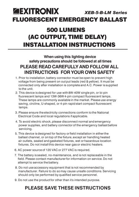
FLUORESCENT EMERGENCY BALLAST INSTALLATION ...
FLUORESCENT EMERGENCY BALLAST INSTALLATION ...
FLUORESCENT EMERGENCY BALLAST INSTALLATION ...

Create successful ePaper yourself
Turn your PDF publications into a flip-book with our unique Google optimized e-Paper software.
<strong>FLUORESCENT</strong> <strong>EMERGENCY</strong> <strong>BALLAST</strong><br />
500 LUMENS<br />
(AC OUTPUT, TIME DELAY)<br />
<strong>INSTALLATION</strong> INSTRUCTIONS<br />
When using this lighting device<br />
safety precautions should be followed at all times<br />
PLEASE READ CAREFULLY AND FOLLOW ALL<br />
INSTRUCTIONS FOR YOUR OWN SAFETY<br />
1. Prior to installation, battery connector must be open to prevent high<br />
voltage from being present on out put leads (red & yellow). It must be<br />
connected only after installation is complete and A.C. Power is supplied<br />
to the unit.<br />
2. This device is designed for use with 8W-40W single pin, or bi-pin<br />
fluorescent lamps and 13W-36W 4-pin compact fluorescent lamps.<br />
These lamps are commonly available in the market. Please use energy<br />
saving, circline, U-shaped, or 4-pin rapid start compact fluorescent<br />
lamps.<br />
3. Please ensure the electricity connections conform to the National<br />
Electrical Code and local regulations if applicable.<br />
4. To avoid electric shock, please disconnect normal and emergency<br />
power supplies, and battery connector of the emergency ballast before<br />
servicing.<br />
6. AC power source of 120 VAC or 277 VAC is required.<br />
7. The battery is sealed, no-maintenance, and is not replaceable in the<br />
field. Please contact manufacturer for information on service. Do not<br />
attempt to service the battery.<br />
8. Do not use accessory equipment that is not recommended by<br />
manufacturer. Failure to do so may cause unsafe conditions. Servicing<br />
should only be performed by qualified service personnel.<br />
9. Do not use the product for other than it s intended purpose.<br />
XEB-5-B-LM Series<br />
5. This device is designed for factory or field installation in either the<br />
ballast channel, or on top of the fixture, except air handling heated<br />
air outlets, sealed and gasketed fixtures, wet or hazardous location<br />
fixtures. Do not install this device near gas or electric heaters.<br />
PLEASE SAVE THESE INSTRUCTIONS
IIIustration 1 IIIustration 2<br />
<strong>EMERGENCY</strong><br />
<strong>BALLAST</strong><br />
7/8 BUSHING<br />
<strong>INSTALLATION</strong> INSTRUCTIONS<br />
CAUTION: Before installing, make certain the A.C. Power is off and the<br />
<strong>EMERGENCY</strong> <strong>BALLAST</strong>'S unit connector is disconnected.<br />
1. MOUNTING THE <strong>EMERGENCY</strong> <strong>BALLAST</strong>(BATTERY PACK)<br />
1 Remove the ballast channel cover. Mount the <strong>EMERGENCY</strong> <strong>BALLAST</strong> in the ballast channel at least / 2 " away from<br />
the A.C. ballast(s).<br />
When battery packs are remote mounted, the remote distance can not exceed 1/ 2 of the distance from ballast to<br />
lamp specified by the A.C. ballast manufacturer. For example, if the A.C. ballast manufacturer recommends no<br />
more than 25' remote distance, then the battery pack's remote mounting distance should not exceed 12 1/ 2 ' .<br />
Under no circumstances should the battery pack exceed a distance of 50' from the lamp(s).<br />
2. WIRING<br />
Refer to the wiring diagrams on the back page for the appropriate wiring of lamp(s) and ballast. Install in accordance<br />
with the National Electrical Code and local regulations. For additional wiring diagrams consult Customer Service.<br />
3. INSTALLING THE LED COMBO TEST SWITCH(LCTS)<br />
Recessed Troffer Fixture - Select a convenient location with proper clearance in the ballast cover and drill or<br />
punch a 7/ 8 hole( 1/ 2 knockout). Insert the 7/ 8 bushing into the hole. Push the plastic tube through the bushing.<br />
Route the leads of the LCTS through the plastic tube. Connect the wires from the unit to the LCTS(VIOLET to<br />
VIOLET, BROWN to BROWN). Push the entire assembly back into the tube until the lens collar rests against the plastic<br />
tube. The plastic tube should be adjusted so that the LCTS is within 1/ 4 of the fixture lens. The LCTS must be<br />
visible after installation. Refer to IIIustration 1.<br />
Strip Fixture - Select a convenient location on the fixture so the LCTS can be seen after installation. Allow for<br />
proper clearance inside the fixture and drill or punch a 1/ 2 hole. Remove the nut from the LCTS. Push the LCTS<br />
housing into the 1/ 2 hole and secure with the nut. Connect the wires from the LCTS (VIOLET to VIOLET,<br />
BROWN to BROWN). Refer to IIIustration2.<br />
Recessed Troffer Fixture Strip Fixture<br />
PLASTIC TUBE<br />
LCTS<br />
FIXTURE<br />
<strong>BALLAST</strong> CHANNEL COVER<br />
4. WIRING THE A.C. INPUT<br />
FIXTURE LENS<br />
<strong>EMERGENCY</strong><br />
<strong>BALLAST</strong><br />
Page 2<br />
FIXTURE<br />
LCTS<br />
BROWN(-)<br />
LEAD<br />
OBSERVE PROPER POLARITY<br />
VIOLET(+)<br />
LEAD<br />
A. The <strong>EMERGENCY</strong> <strong>BALLAST</strong> and A.C. ballast must be on the same branch circuit<br />
B. The <strong>EMERGENCY</strong> <strong>BALLAST</strong> requires an unswitched A.C. power source of either 120 or 277 volts. Select<br />
the proper voltage lead and cap the unused lead.<br />
C. When the <strong>EMERGENCY</strong> <strong>BALLAST</strong> is used with a switched fixture, A.C. Input to the <strong>EMERGENCY</strong> <strong>BALLAST</strong><br />
must be connected ahead of the fixture switch. Refer to IIIustration 3 for switched and unswitched fixture wiring<br />
diagrams.
5. <strong>BALLAST</strong> WIRING BLOCK DIAGRAM<br />
IIIustration 3 Switched Fixture Unswitched Fixture<br />
HOT A.C.LINE<br />
COMMON<br />
LCTS<br />
6. LABELS<br />
1<br />
BROWN(-)<br />
VIOLET(+)<br />
BLACK<br />
WHITE<br />
WHT/BLK<br />
WHITE<br />
(277V) ORG<br />
(120V)BLK<br />
BROWN(-)<br />
VIOLET(+)<br />
A.C.<strong>BALLAST</strong><br />
<strong>EMERGENCY</strong><br />
<strong>BALLAST</strong><br />
1 Select proper voltage lead.Cap unused lead.<br />
7. COMPLETING <strong>INSTALLATION</strong><br />
HOT A.C.LINE<br />
COMMON<br />
LCTS<br />
1<br />
BLACK<br />
WHITE<br />
WHT/BLK<br />
WHITE<br />
(277V) ORG<br />
(120V)BLK<br />
BROWN(-) BROWN(-)<br />
VIOLET(+) VIOLET(+)<br />
A.C.<strong>BALLAST</strong><br />
<strong>EMERGENCY</strong><br />
<strong>BALLAST</strong><br />
1 Select proper voltage lead.Cap unused lead.<br />
Attach the appropriate labels adjacent to the LCTS. Annotate Re-lamping label for lamp type and wattage. The<br />
'Caution' and the 'Re-lamping' labels must be on the fixture in a readily visible location to anyone attempting to<br />
service the fixture.<br />
When the installation is complete, switch the A.C. power ON and join the <strong>EMERGENCY</strong> <strong>BALLAST</strong> ' S unit connector.<br />
OPERATION<br />
Normal Mode - A.C. power is present. The A.C. ballast operates the fluorescent lamp(s) as intended. The LCTS will be<br />
lit providing a visual indication that the <strong>EMERGENCY</strong> <strong>BALLAST</strong> is in the standby charging mode.<br />
Emergency Mode - A.C. power fails. The <strong>EMERGENCY</strong> <strong>BALLAST</strong> senses the A.C. power failure and automatically<br />
switches to the Emergency Mode. One lamp is illuminated at reduced output, for a minimum of 90 minutes. When A.C.<br />
Power is restored, the <strong>EMERGENCY</strong> <strong>BALLAST</strong> switches the system back to the Normal Mode and resumes battery<br />
charging.<br />
TESTING & MAINTENANCE<br />
Pressing the red lens on the LCTS turns off the light on it, interrupts power to the designated A.C. ballast and forces the<br />
unit into emergency mode. The emergency lamp (s) is (are) now lit by the <strong>EMERGENCY</strong> <strong>BALLAST</strong>. On releasing the<br />
lens, fixture returns to normal mode after a momentary delay. To simulate a BLACK OUT use the circuit breaker to<br />
turn off the AC power.<br />
Initial Testing - Allow the unit to charge for approximately 1 hour, then press the LCTS to conduct a short discharge test.<br />
Allow a 24 hour charge before conducting a 1 1/ 2 hour test.<br />
This <strong>EMERGENCY</strong> <strong>BALLAST</strong> is a maintenance free unit, however, periodic inspection and testing is required. NFPA 101,<br />
Life Safety Code, outlines the following schedule:<br />
Monthly - Insure that the LCTS is illuminated. Conduct a 30 second discharge test by depressing the LCTS. One lamp<br />
should operate at reduced output.<br />
Annually - Insure that the LCTS is illuminated. Conduct a full 1 1/ 2 hour discharge test. The unit should operate as<br />
intended for the duration of the test.<br />
Written records of testing shall be kept by the owner for inspection by the authority having jurisdiction.<br />
SERVICING SHOULD BE PERFORMED BY QUALIFIED PERSONNEL.<br />
Page 3
A. Rapid Start AC Ballast B. Instant Start Slimline Ballast<br />
BLACK<br />
WHITE<br />
BLACK<br />
WHITE<br />
WIRE DIAGRAMS FOR LAMP <strong>EMERGENCY</strong> OPERATION<br />
<strong>EMERGENCY</strong> <strong>BALLAST</strong> AND AC <strong>BALLAST</strong> MUST BE FED FROM THE SAME BRANCH CIRCUIT<br />
TYPICAL SCHEMATICS ONLY. MAY BE USED WITH OTHER <strong>BALLAST</strong>S. CONSULT THE FACTORY FOR OTHER WIRING DIAGRAMS.<br />
AC<br />
<strong>BALLAST</strong><br />
LAMP<br />
LAMP<br />
RED<br />
RED<br />
BLUE<br />
BLUE<br />
BLUE<br />
RED<br />
RED<br />
BLUE<br />
BLU/WHT<br />
YELL/BLK<br />
YELLOW<br />
VIOLET +<br />
_<br />
BROWN<br />
LCTS<br />
C. Circline Rapid Start Ballast<br />
LCTS<br />
BLUE<br />
BLU/WHT<br />
YELL/BLK<br />
YELLOW<br />
VIOLET +<br />
_<br />
BROWN<br />
A. Rapid Start AC Ballast<br />
BLACK<br />
WHITE<br />
YELLOW<br />
YELLOW<br />
LAMP 1<br />
<strong>EMERGENCY</strong> LAMP<br />
BLUE<br />
BLUE<br />
RED<br />
RED<br />
BLUE<br />
BLU/WHT<br />
YELL/BLK<br />
LCTS<br />
YELLOW<br />
VIOLET +<br />
_<br />
BROWN<br />
_<br />
<strong>EMERGENCY</strong><br />
<strong>EMERGENCY</strong><br />
<strong>BALLAST</strong><br />
<strong>EMERGENCY</strong><br />
<strong>BALLAST</strong><br />
ORANGE(277V)<br />
WHITE<br />
RED<br />
COMMON<br />
BATTERY<br />
CONNECTOR<br />
SWITCHED OR<br />
UNSWITCHED<br />
LINE<br />
1<br />
1 SELECT PROPER VOLTAGE<br />
LEAD. CAP UNUSED LEAD.<br />
2 DO NOT MATE CONNECTOR<br />
UNTIL <strong>INSTALLATION</strong> IS<br />
COMPLETE AND AC POWER<br />
IS SUPPLED<br />
1 SELECT PROPER VOLTAGE<br />
LEAD. CAP UNUSED LEAD.<br />
2 DO NOT MATE CONNECTOR<br />
UNTIL <strong>INSTALLATION</strong> IS<br />
COMPLETE AND AC POWER<br />
IS SUPPLED<br />
BLACK<br />
WHITE<br />
For 2 Lamp Fixture<br />
1 SELECT PROPER VOLTAGE<br />
LEAD. CAP UNUSED LEAD.<br />
2 DO NOT MATE CONNECTOR<br />
UNTIL <strong>INSTALLATION</strong> IS<br />
COMPLETE AND AC POWER<br />
IS SUPPLED<br />
1 SELECT PROPER VOLTAGE<br />
LEAD. CAP UNUSED LEAD.<br />
2 DO NOT MATE CONNECTOR<br />
UNTIL <strong>INSTALLATION</strong> IS<br />
COMPLETE AND AC POWER<br />
IS SUPPLED<br />
LAMP<br />
BLUE BLUE<br />
OR<br />
RED<br />
BLU/WHT<br />
YELL/BLK<br />
LCTS<br />
YELLOW<br />
VIOLET +<br />
_<br />
BROWN<br />
_<br />
_<br />
_<br />
<strong>EMERGENCY</strong><br />
<strong>BALLAST</strong><br />
RED<br />
WHITE<br />
RED<br />
BLACK(120V)<br />
WHITE<br />
SWITCHED OR<br />
UNSWITCHED<br />
LINE<br />
ORANGE(277V)<br />
1<br />
BLACK(120V) UNSWITCHED<br />
WHITE<br />
COMMON<br />
BATTERY<br />
CONNECTOR<br />
RED<br />
WHITE<br />
C. Serves Sequence Instant Start Ballast<br />
BLACK<br />
WHITE<br />
AC<br />
<strong>BALLAST</strong><br />
AC<br />
<strong>BALLAST</strong><br />
AC<br />
<strong>BALLAST</strong><br />
LAMP 1<br />
<strong>EMERGENCY</strong> LAMP<br />
BLUE<br />
RED<br />
BLUE<br />
BLU/WHT<br />
YELL/BLK<br />
YELLOW<br />
VIOLET +<br />
_<br />
BROWN<br />
LCTS<br />
WHT/BLK<br />
WHT/BLK<br />
WHT/BLK<br />
WHT/BLK<br />
<strong>EMERGENCY</strong><br />
<strong>BALLAST</strong><br />
WHITE<br />
RED<br />
BATTERY<br />
CONNECTOR<br />
UNSWITCHED<br />
SWITCHED OR<br />
UNSWITCHED<br />
LINE<br />
ORANGE(277V)<br />
1<br />
BLACK(120V) UNSWITCHED<br />
COMMON<br />
D. Instant Start Ballast<br />
BLACK<br />
WHITE<br />
RED<br />
AC<br />
<strong>BALLAST</strong><br />
LAMP<br />
BLUE BLUE<br />
BLU/WHT<br />
YELL/BLK<br />
YELLOW<br />
RED<br />
<strong>EMERGENCY</strong><br />
<strong>BALLAST</strong><br />
<strong>EMERGENCY</strong><br />
<strong>BALLAST</strong><br />
RED WHITE<br />
WHT/BLK BATTERY<br />
CONNECTOR<br />
ORANGE(277V)<br />
1<br />
LCTS<br />
BLACK(120V)<br />
WHITE<br />
RED<br />
WHITE<br />
RED<br />
SWITCHED OR<br />
UNSWITCHED<br />
LINE<br />
UNSWITCHED<br />
COMMON<br />
BATTERY<br />
CONNECTOR<br />
SWITCHED OR<br />
UNSWITCHED<br />
LINE<br />
ORANGE(277V)<br />
1<br />
BLACK(120V) UNSWITCHED<br />
WHITE<br />
COMMON<br />
B. LEAD/LAG Instant Start Slimline Ballast<br />
BLACK<br />
WHITE<br />
LAMP 1<br />
<strong>EMERGENCY</strong> LAMP<br />
BLUE BLUE<br />
RED<br />
BLU/WHT<br />
YELL/BLK<br />
YELLOW<br />
VIOLET +<br />
_<br />
BROWN<br />
LCTS<br />
_<br />
_<br />
ORANGE(277V)<br />
BLACK(120V)<br />
WHITE<br />
RED<br />
WHITE<br />
RED<br />
For 1 Lamp Fixture<br />
RED<br />
1<br />
UNSWITCHED<br />
COMMON<br />
BATTERY<br />
CONNECTOR<br />
2<br />
SWITCHED OR<br />
UNSWITCHED<br />
LINE<br />
2<br />
2<br />
2<br />
BLACK<br />
WHITE<br />
AC<br />
<strong>BALLAST</strong><br />
AC<br />
<strong>BALLAST</strong><br />
LAMP 1<br />
<strong>EMERGENCY</strong> LAMP<br />
BLUE BLUE<br />
RED<br />
BLU/WHT<br />
YELLOW<br />
VIOLET +<br />
_<br />
BROWN<br />
<strong>EMERGENCY</strong><br />
<strong>BALLAST</strong><br />
D. Instant Start Electronic Ballast<br />
AC<br />
<strong>BALLAST</strong><br />
BLUE<br />
YELL/BLK<br />
NOTE: Use proper tap to cap unswitched AC lead<br />
LCTS<br />
WHT/BLK<br />
WHT/BLK<br />
_<br />
2<br />
WHT/BLK<br />
<strong>EMERGENCY</strong><br />
<strong>BALLAST</strong><br />
ORANGE(277V)<br />
WHITE<br />
RED<br />
WHITE<br />
RED<br />
BATTERY<br />
CONNECTOR<br />
1 SELECT PROPER VOLTAGE<br />
LEAD. CAP UNUSED LEAD.<br />
2 DO NOT MATE CONNECTOR<br />
UNTIL <strong>INSTALLATION</strong> IS<br />
COMPLETE AND AC POWER<br />
IS SUPPLED<br />
1 SELECT PROPER VOLTAGE<br />
LEAD. CAP UNUSED LEAD.<br />
2 DO NOT MATE CONNECTOR<br />
UNTIL <strong>INSTALLATION</strong> IS<br />
COMPLETE AND AC POWER<br />
IS SUPPLED<br />
SWITCHED OR<br />
UNSWITCHED<br />
LINE<br />
1<br />
BLACK(120V) UNSWITCHED<br />
RED<br />
WHITE<br />
RED<br />
COMMON<br />
1 SELECT PROPER VOLTAGE<br />
LEAD. CAP UNUSED LEAD.<br />
2 DO NOT MATE CONNECTOR<br />
UNTIL <strong>INSTALLATION</strong> IS<br />
COMPLETE AND AC POWER<br />
IS SUPPLED<br />
ORANGE(277V)<br />
1<br />
BLACK(120V) UNSWITCHED<br />
WHITE<br />
SWITCHED OR<br />
UNSWITCHED<br />
LINE<br />
2<br />
COMMON<br />
BATTERY<br />
CONNECTOR<br />
2<br />
2<br />
1 SELECT PROPER VOLTAGE<br />
LEAD. CAP UNUSED LEAD.<br />
2 DO NOT MATE CONNECTOR<br />
UNTIL <strong>INSTALLATION</strong> IS<br />
COMPLETE AND AC POWER<br />
IS SUPPLED
BLACK<br />
WHITE<br />
BLUE<br />
WHITE<br />
RED<br />
RED<br />
WIRE DIAGRAMS FOR LAMP <strong>EMERGENCY</strong> OPERATION<br />
<strong>EMERGENCY</strong> <strong>BALLAST</strong> AND AC <strong>BALLAST</strong> MUST BE FED FROM THE SAME BRANCH CIRCUIT<br />
TYPICAL SCHEMATICS ONLY. MAY BE USED WITH OTHER <strong>BALLAST</strong>S. CONSULT THE FACTORY FOR OTHER WIRING DIAGRAMS.<br />
For 2 Lamp Fixture<br />
E. Circline Rapid Start Ballast<br />
LAMP 1<br />
<strong>EMERGENCY</strong><br />
LAMP<br />
RED<br />
RED<br />
BLUE<br />
WHITE<br />
A. Rapid Start Ballast<br />
BLACK<br />
WHITE<br />
LAMP 1<br />
LAMP 2<br />
<strong>EMERGENCY</strong> LAMP<br />
A. Instant Start Ballast<br />
BLACK<br />
WHITE<br />
YELLOW<br />
YELLOW<br />
AC<br />
<strong>BALLAST</strong><br />
AC<br />
<strong>BALLAST</strong><br />
AC<br />
<strong>BALLAST</strong><br />
LAMP 1<br />
LAMP 2<br />
LAMP 3<br />
<strong>EMERGENCY</strong> LAMP<br />
BLUE<br />
BLU/WHT<br />
YELL/BLK<br />
YELLOW<br />
VIOLET +<br />
_<br />
BROWN<br />
LCTS<br />
_<br />
<strong>EMERGENCY</strong><br />
<strong>BALLAST</strong><br />
SWITCHED OR<br />
UNSWITCHED<br />
LINE<br />
ORANGE(277V)<br />
1<br />
BLACK(120V) UNSWITCHED<br />
WHITE<br />
RED<br />
WHITE<br />
RED<br />
COMMON<br />
BATTERY<br />
CONNECTOR<br />
1 SELECT PROPER VOLTAGE<br />
LEAD. CAP UNUSED LEAD.<br />
2 DO NOT MATE CONNECTOR<br />
UNTIL <strong>INSTALLATION</strong> IS<br />
COMPLETE AND AC POWER<br />
IS SUPPLED<br />
SWITCHED OR<br />
UNSWITCHED<br />
LINE<br />
BLUE BLUE<br />
ORANGE(277V)<br />
BLUE<br />
BLU/WHT<br />
BLACK(120V) 1<br />
UNSWITCHED<br />
BLUE/WHT<br />
BLUE/WHT<br />
YELLOW<br />
YELLOW<br />
RED<br />
RED<br />
YELL/BLK<br />
YELLOW<br />
VIOLET +<br />
_<br />
BROWN<br />
<strong>EMERGENCY</strong><br />
<strong>BALLAST</strong><br />
WHITE<br />
RED<br />
WHITE<br />
RED<br />
COMMON<br />
2<br />
BLUE BLUE<br />
BLUE<br />
RED<br />
RED<br />
LCTS<br />
BLUE/WHITE<br />
YELL/BLK<br />
YELLOW<br />
VIOLET +<br />
_<br />
BROWN<br />
LCTS<br />
<strong>EMERGENCY</strong><br />
<strong>BALLAST</strong><br />
For 3 Lamp Fixture<br />
For 4 Lamp Fixture<br />
Emergency only<br />
One (1) Lamp Without AC Ballast<br />
NOTE: Use proper tap to cap unswitched AC lead<br />
LAMP<br />
CAP<br />
CAP<br />
BLUE<br />
BLU/WHT<br />
YELL/BLK<br />
YELLOW<br />
VIOLET +<br />
_<br />
BROWN<br />
LCTS<br />
WHT/BLK<br />
CAP<br />
_<br />
_<br />
BATTERY<br />
CONNECTOR<br />
1 SELECT PROPER VOLTAGE<br />
LEAD. CAP UNUSED LEAD.<br />
2 DO NOT MATE CONNECTOR<br />
UNTIL <strong>INSTALLATION</strong> IS<br />
COMPLETE AND AC POWER<br />
IS SUPPLED<br />
B. Instant start Ballast<br />
BLACK<br />
WHITE<br />
LAMP 1<br />
LAMP 2<br />
<strong>EMERGENCY</strong> LAMP<br />
BLUE BLUE<br />
BLUE<br />
BLUE<br />
RED<br />
BLUE/WHITE<br />
YELL/BLK<br />
YELLOW<br />
VIOLET +<br />
_<br />
BROWN<br />
LCTS<br />
_<br />
_<br />
WHT/BLK<br />
WHT/BLK<br />
SWITCHED OR<br />
UNSWITCHED<br />
LINE<br />
ORANGE(277V)<br />
1<br />
BLACK(120V) UNSWITCHED<br />
WHITE<br />
RED<br />
WHITE<br />
RED<br />
2<br />
COMMON<br />
2<br />
B. Rapid Stapt Ballast<br />
BLACK<br />
WHITE<br />
YELLOW<br />
YELLOW<br />
BLUE<br />
BLUE/WHITE<br />
YELL/BLK<br />
BATTERY<br />
CONNECTOR<br />
LAMP 1<br />
LAMP 2<br />
WHT/BLK<br />
LAMP 3<br />
WHT/BLK<br />
1 SELECT PROPER VOLTAGE<br />
LEAD. CAP UNUSED LEAD.<br />
2 DO NOT MATE CONNECTOR<br />
UNTIL <strong>INSTALLATION</strong> IS<br />
COMPLETE AND AC POWER<br />
IS SUPPLED<br />
<strong>EMERGENCY</strong> LAMP<br />
BROWN<br />
BROWN<br />
AC<br />
<strong>BALLAST</strong><br />
AC<br />
<strong>BALLAST</strong><br />
RED<br />
RED<br />
BLUE/WHITE<br />
BLUE/WHITE<br />
BLUE<br />
BLUE<br />
YELLOW<br />
VIOLET +<br />
_<br />
BROWN<br />
LCTS<br />
_<br />
WHT/BLK<br />
<strong>EMERGENCY</strong><br />
<strong>BALLAST</strong><br />
<strong>EMERGENCY</strong><br />
<strong>BALLAST</strong><br />
<strong>EMERGENCY</strong><br />
<strong>BALLAST</strong><br />
RED<br />
WHITE<br />
RED<br />
RED<br />
WHITE<br />
RED<br />
ORANGE(277V)<br />
1<br />
BLACK(120V) UNSWITCHED<br />
WHITE<br />
RED<br />
WHITE<br />
RED<br />
COMMON<br />
BATTERY<br />
CONNECTOR<br />
ORANGE(277V)<br />
1<br />
BLACK(120V) UNSWITCHED<br />
2<br />
WHITE<br />
BATTERY<br />
CONNECTOR<br />
COMMON<br />
BATTERY<br />
CONNECTOR<br />
SWITCHED OR<br />
UNSWITCHED<br />
LINE<br />
ORANGE(277V)<br />
1<br />
BLACK(120V) UNSWITCHED<br />
WHITE<br />
COMMON<br />
2<br />
2<br />
SWITCHED OR<br />
UNSWITCHED<br />
LINE<br />
1 SELECT PROPER VOLTAGE<br />
LEAD. CAP UNUSED LEAD.<br />
2 DO NOT MATE CONNECTOR<br />
UNTIL <strong>INSTALLATION</strong> IS<br />
COMPLETE AND AC POWER<br />
IS SUPPLED<br />
SELECT PROPER VOLTAGE<br />
1 LEAD. CAP UNUSED LEAD.<br />
DO NOT MATE CONNECTOR<br />
2 UNTIL <strong>INSTALLATION</strong> IS<br />
COMPLETE AND AC POWER<br />
IS SUPPLED<br />
1 SELECT PROPER VOLTAGE<br />
LEAD. CAP UNUSED LEAD.<br />
2 DO NOT MATE CONNECTOR<br />
UNTIL <strong>INSTALLATION</strong> IS<br />
COMPLETE AND AC POWER<br />
IS SUPPLED