ABR/S-BVR/S INSTALLATION INSTRUCTIONS - LSI Industries Inc.
ABR/S-BVR/S INSTALLATION INSTRUCTIONS - LSI Industries Inc.
ABR/S-BVR/S INSTALLATION INSTRUCTIONS - LSI Industries Inc.

You also want an ePaper? Increase the reach of your titles
YUMPU automatically turns print PDFs into web optimized ePapers that Google loves.
<strong>ABR</strong>/S-<strong>BVR</strong>/S <strong>INSTALLATION</strong> <strong>INSTRUCTIONS</strong><br />
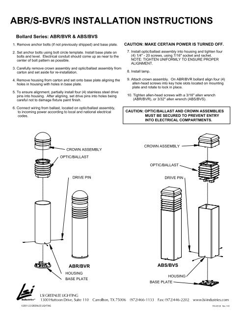
Bollard Series: <strong>ABR</strong>/<strong>BVR</strong> & ABS/BVS<br />
1. Remove anchor bolts (if not previously shipped) and base plate.<br />
2. Set anchor bolts using bolt circle template. Install base plate on<br />
bolts and level. Electrical conduit should come up as near to the<br />
center of bolt pattern as possible.<br />
3. Carefully remove crown assembly and optic/ballast assembly from<br />
carton and set aside for re-installation.<br />
4. Remove housing from carton and set onto base plate aligning the<br />
holes in housing with holes in base plate.<br />
5. To ensure alignment, partially install four (4) stainless steel drive<br />
pins into housing. After aligning, set drive pins into holes being<br />
careful not to damage fixture paint finish.<br />
6. Connect wiring from ballast, located on optic/ballast assembly,<br />
to incoming power according to local and national electrical<br />
codes.<br />
©2001 <strong>LSI</strong> GREENLEE LIGHTING<br />
CROWN ASSEMBLY<br />
OPTIC/BALLAST<br />
DRIVE PIN<br />
<strong>ABR</strong>/<strong>BVR</strong><br />
HOUSING<br />
BASE PLATE<br />
CAUTION: MAKE CERTAIN POWER IS TURNED OFF.<br />
7. Install optic/ballast assembly into housing and tighten four<br />
(4) 1/4" - 20 screws, using 7/16" socket and rachet.<br />
NOTE: TIGHTEN UNIFORMLY TO ENSURE PROPER<br />
ALIGNMENT.<br />
8. Install lamp.<br />
9. Attach crown assembly. On <strong>ABR</strong>/<strong>BVR</strong> bollard align four (4)<br />
allen-head screws into key hole slots located on mounting<br />
plate and rotate to lock in place.<br />
10. Tighten allen-head screws with a 3/16" allen wrench<br />
(<strong>ABR</strong>/<strong>BVR</strong>), or 3/32" allen wrench (ABS/BVS).<br />
CAUTION: OPTIC/BALLAST AND CROWN ASSEMBLIES<br />
MUST BE SECURED TO PREVENT ENTRY<br />
INTO ELECTRICAL COMPARTMENTS.<br />
CROWN ASSEMBLY<br />
OPTIC/BALLAST<br />
DRIVE PIN<br />
ABS/BVS<br />
BASE PLATE<br />
HOUSING<br />
<strong>LSI</strong> GREENLEE LIGHTING<br />
1300 Huttoon Drive, Suite 110 Carrollton, TX 75006 (972)466-1133 Fax: (972)446-2202 www.lsi-industries.com<br />
P/N 45128 Rev. 1/01
WARNING:<br />
CAUTION:<br />
ATTENTION:<br />
ATTENTION:<br />
NOTE:<br />
Fixture Installation:<br />
This Fixture Must Be Installed Per Local And National Electric Codes. This Fixture Must Be Grounded!<br />
Failure To Do So May Result In Serious Personal Injury.<br />
This Fixture Must Be Installed By A Qualified Licensed Electrician.<br />
Hid Versions Of This Fixture Are Equipped With A Multi-Tap Ballast And Have Been Factory Wired For Operation On A<br />
277 Volt Circuit (347V In Canada). If Other Than 277V Is Required, I.E. 120V, 208V, 240V, Connect <strong>Inc</strong>oming Voltage Lead<br />
To Selected Voltage On Ballast. All Unused Leads Must Be Insulated.<br />
Fluorescent Versions Are Equipped With A Universal Voltage Electronic Fluorescent Ballast. The Electronic Ballast Will<br />
Accomodate Input Voltages From 120V Thru 277V 50/60Hz. The Electronic Ballast Will Operate Pl-T 26W/4P, Pl-T 32W/4P,<br />
Pl-T 42W/4P Lamps. The Lampholder Provided Will Accept Any Of These Lamps. See Page 2 For Fluorescent Lamp Installation Detail.<br />
KEEP THESE <strong>INSTRUCTIONS</strong> FOR FUTURE REFERENCE.<br />
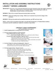
Refer to the bollard anchor bolt template<br />
for proper installation of anchor bolts<br />
Level base plate with bubble level before<br />
securing top nuts & washers<br />
Concrete<br />
(By Others)<br />
FIGURE 1<br />
Electrical Conduit<br />
(By Others)<br />
TOOLS REQUIRED: • T-25 TORX DRIVER<br />
• 1/8" L-TYPE HEX KEY<br />
VBR/VBS Bollard Series<br />
Installation Instructions<br />
VBS ID<br />
Shown<br />
• 5/32" HEX KEY<br />
• BUBBLE LEVEL<br />
ID<br />
Reflector<br />
Lamp Access<br />
Cap Assy<br />
Ballast/Optic<br />
Assy<br />
Housing<br />
Extrusion<br />
1/4-20 X 1/2<br />
Cap Screw<br />
Base Plate<br />
IL<br />
Reflector<br />
Assy<br />
• 9/16" OPEN END WRENCH<br />
VBR IL<br />
Shown<br />
1. Make certain the power supply is turned off before starting installation.<br />
2. Mount base plate on anchor bolts. See figure 1 & anchor bolt mounting template.<br />
3. Slide the housing extrusion over the base plate, align the machined holes in the bottom of the housing extrusion with the holes in the base<br />
plate. Insert four 1/4-20 x 1/2 cap screws and tighten with the 5/32" hex key.<br />
4. Make all supply lead connections to the ballast, refer to schematic on ballast if necessary. All ballast leads must be insulated.<br />
Slide ballast/optic assy into top of housing extrusion.<br />
5. Remove the lamp & reflector and tighten all set screws on the ballast/optic assy with a 1/8" l-type hex key. See page 2 for ballast/optic<br />
assy installation details.<br />
6. Replace lamp & reflector and insert lamp access cap onto top of ballast/optic assy. Align the (2) #10-24 captive screws before pushing<br />
cap gasket into top of ballast/optic assy. once aligned, press the cap in firmly and tighten the (2) #10-24 captive screws. See page 2 for<br />
lamp access cap installation details.<br />
PAGE 1<br />
P/N 45209 REV. 2-9-01
Figure 2. Ballast/Optic Assembly Installation<br />
BALLAST/OPTIC ASSY<br />
MOUNTING SET SCREW<br />
LOCATIONS<br />
VBR SET SCREW (3X) VBS SET SCREW (4X)<br />
After connecting all supply leads, insert ballast/optic assy into housing extrusion. With lamp & reflector removed, tighten all<br />
1/4-20 set screws to 25 IN/LB torque with a 1/8" L-type hex key.<br />
Figure 4. Captive Screw Details<br />
Maintenance:<br />
VBR/VBS Bollard Series<br />
Installation Instructions<br />
Figure 3. Lamp Access Cap Installation<br />
Align the #10-24 captive screws in the lamp access cap with the holes on the weldment<br />
tabs, and tighten 1 to 2 turns. Press the lamp access cap in place firmly. Tighten the<br />
captive screws to 30 IN/LB with a T-25 torx driver.<br />
Stainless Steel Washer<br />
Lamp Access Cap Screw Hole Seal<br />
(Prevents Water Entry Into Fixture)<br />
Captive Screw Retainer<br />
(Prevents Screw From Falling<br />
Out Of Lamp Access Cap)<br />
CAPTIVE SCREWS<br />
WELDMENT TAB<br />
Figure 5. Fluorescent Relamping<br />
OFF ON<br />
Fluorescent fixtures are<br />
supplied with "twist-lock"<br />
lampholders. To install<br />
lamp, press the lamp into the<br />
lampholder & turn clockwise<br />
until the lampholder clicks.<br />
Turn the lamp counterclockwise<br />
until the<br />
lampholder clicks to release<br />
lamp.<br />
This fixture should be periodically maintained. If service parts are required a parts list can be obtained bycontacting your local distributor or calling<br />
<strong>LSI</strong> GREENLEE LIGHTING customer service @ 972-466-1133. Failure to follow the manufacturers instructions, or making any modifications to the<br />
product can void the warranty. Fixture failures resulting from poor maintenance or abuse will not be covered by warranty. consult<br />
warranty for full details.<br />
<strong>LSI</strong> GREENLEE LIGHTING 1300 Hutton Dr. Ste. 110 Carrollton, TX 75006 (972)466-1133.<br />
PAGE 2<br />
© Copyright 2001 <strong>LSI</strong> GREENLEE LIGHTING<br />
P/N 45209 REV.