Chapter 12: Radiation Heat Transfer
Chapter 12: Radiation Heat Transfer
Chapter 12: Radiation Heat Transfer

You also want an ePaper? Increase the reach of your titles
YUMPU automatically turns print PDFs into web optimized ePapers that Google loves.
<strong>Chapter</strong> <strong>12</strong>: <strong>Radiation</strong> <strong>Heat</strong> <strong>Transfer</strong><br />
<strong>Radiation</strong> differs from Conduction and Convection heat t transfer mechanisms, in<br />
the sense that it does not require the presence of a material medium to occur.<br />
Energy transfer by radiation occurs at the speed of light and suffers no attenuation<br />
in vacuum.<br />
<strong>Radiation</strong> can occur between two bodies separated by a medium colder than both<br />
bodies.<br />
According to Maxwell theory, energy transfer takes place via electromagnetic<br />
waves in radiation. Electromagnetic waves transport energy like other waves and<br />
travel at the speed of light.<br />
Electromagnetic waves are characterized by their frequency ν (Hz) and<br />
wavelength λ (µm), where:<br />
λ = c / ν<br />
where c is the speed of light in that medium; in a vacuum c0 = 2.99 x 10 8 m / s.<br />
Note that the frequency and wavelength are inversely proportional.<br />
The speed of light in a medium is related to the speed of light in a vacuum,<br />
c = c0 / n<br />
where n is the index of refraction of the medium, n = 1 for air and n = 1.5 for water.<br />
Note that the frequency of an electromagnetic wave depends only on the source<br />
and is independent of the medium.<br />
The frequency of an electromagnetic wave can range from a few cycles to millions<br />
of cycles and higher per second.<br />
Einstein postulated another theory for electromagnetic radiation. Based on this<br />
theory, electromagnetic radiation is the propagation of a collection of discrete<br />
packets of energy called photons. In this view, each photon of frequency ν is<br />
considered to have energy of<br />
e = hν = hc / λ<br />
where h = 6.625 x 10 -34 J.s is the Planck’s constant.<br />
Note that in Einstein’s theory h and c are constants, thus the energy of a photon is<br />
inversely proportional to its wavelength. Therefore, shorter wavelength radiation<br />
possesses more powerful photon energies (X-ray and gamma rays are highly<br />
destructive).<br />
<strong>Chapter</strong> <strong>12</strong>, E&CE 309, Spring 2005. 1<br />
Majid Bahrami
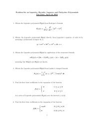
Fig. <strong>12</strong>-1: Electromagnetic spectrum.<br />
Electromagnetic radiation covers a wide range of wavelength, from 10 -10 µm for<br />
cosmic rays to 10 10 µm for electrical power waves.<br />
As shown in Fig. <strong>12</strong>-1, thermal radiation wave is a narrow band on the<br />
electromagnetic wave spectrum.<br />
Thermal radiation emission is a direct result of vibrational and rotational motions of<br />
molecules, atoms, and electrons of a substance. Temperature is a measure of<br />
these activities. Thus, the rate of thermal radiation emission increases with<br />
increasing temperature.<br />
What we call light is the visible portion of the electromagnetic spectrum which lies<br />
within the thermal radiation band.<br />
Thermal radiation is a volumetric phenomenon. However, for opaque solids such<br />
as metals, radiation is considered to be a surface phenomenon, since the radiation<br />
emitted by the interior region never reach the surface.<br />
Note that the radiation characteristics of surfaces can be changed completely by<br />
applying thin layers of coatings on them.<br />
Blackbody <strong>Radiation</strong><br />
A blackbody is defined as a perfect emitter and absorber of radiation. At a<br />
specified temperature and wavelength, no surface can emit more energy than a<br />
blackbody.<br />
A blackbody is a diffuse emitter which means it emits radiation uniformly in all<br />
direction. Also a blackbody absorbs all incident radiation regardless of wavelength<br />
and direction.<br />
<strong>Chapter</strong> <strong>12</strong>, E&CE 309, Spring 2005. 2<br />
Majid Bahrami
The radiation energy emitted by a blackbody per unit time and per unit surface<br />
area can be determined from the Stefan-Boltzmann Law:<br />
<strong>Chapter</strong> <strong>12</strong>, E&CE 309, Spring 2005. 3<br />
Majid Bahrami<br />
E b<br />
= σT<br />
where<br />
σ = 5.<br />
67 × 10<br />
4<br />
2 ( W / m )<br />
−8<br />
W<br />
2<br />
m K<br />
where T is the absolute temperature of the surface in K and Eb is called the<br />
blackbody emissive power.<br />
A large cavity with a small opening closely resembles a blackbody.<br />
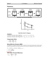
Fig. <strong>12</strong>-2: Variation of blackbody emissive power with wavelength<br />
Spectral blackbody emissive power is the amount of radiation energy emitted by a<br />
blackbody at an absolute temperature T per unit time, per unit surface area, and<br />
per unit wavelength.<br />
Ebλ C<br />
C<br />
1<br />
2<br />
( T )<br />
=<br />
= 2πhc<br />
= hc<br />
0<br />
5<br />
λ<br />
2<br />
0<br />
[ exp(<br />
C / λT<br />
) −1]<br />
/ k = 1.<br />
439<br />
k = 1.<br />
3805×<br />
10<br />
−23<br />
C<br />
2<br />
1<br />
8<br />
= 3.<br />
742×<br />
10<br />
4<br />
⎛ W ⎞<br />
⎜ ⎟ 2<br />
⎝ m . µ m ⎠<br />
4 2 ( W.<br />
µ m / m )<br />
4<br />
× 10 ( µ m.<br />
K )<br />
( J / K ) Boltzmann's<br />
constant<br />
This is called Plank’s distribution law and is valid for a surface in a vacuum or gas.<br />
For other mediums, it needs to be modified by replacing C1 by C1/n 2 , where n is<br />
the index of refraction of the medium,
The wavelength at which the peak emissive power occurs for a given temperature<br />
can be obtained from Wien’s displacement law:<br />
<strong>Chapter</strong> <strong>12</strong>, E&CE 309, Spring 2005. 4<br />
Majid Bahrami<br />
( λ T ) power = 2897.<br />
8 µ m.<br />
K<br />
max<br />
It can be shown that integration of the spectral blackbody emissive power Ebλ over<br />
the entire wavelength spectrum gives the total blackbody emissive power Eb:<br />
Eb ∞<br />
= ∫<br />
0<br />
bλ<br />
4<br />
2<br />
( T ) E ( T ) dλ<br />
= σT<br />
( W / m )<br />
The Stefan-Boltzmann law gives the total radiation emitted by a blackbody at all<br />
wavelengths from 0 to infinity. But, we are often interested in the amount of<br />
radiation emitted over some wavelength band.<br />
To avoid numerical integration of the Planck’s equation, a non-dimensional<br />
quantity fλ is defined which is called the blackbody radiation function as<br />
( T )<br />
λ<br />
∫<br />
0<br />
f λ =<br />
4<br />
σT<br />
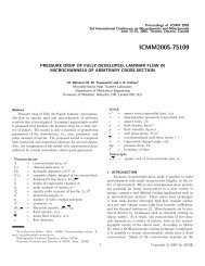
The function fλ represents the fraction of radiation emitted from a blackbody at<br />
temperature T in the wavelength band from 0 to λ. Table <strong>12</strong>-2 in Cengel book lists<br />
fλ as a function of λT.<br />
Therefore, one can write:<br />
Ebλ<br />
f<br />
f<br />
λ −λ<br />
1<br />
λ−∞<br />
λ1<br />
E<br />
bλ<br />
( T )<br />
dλ<br />
2 ( T ) = f λ 2 ( T ) − f λ1(<br />
T )<br />
( T ) = 1−<br />
f ( T )<br />
Fig. <strong>12</strong>-3: Fraction of radiation emitted in the wavelength between λ1 and λ2<br />
λ<br />
Ebλ(T)<br />
λ2<br />
λ
Example <strong>12</strong>-1<br />
The temperature of the filament of a light bulb is 2500 K. Assuming the filament to<br />
be a blackbody, determine the fraction of the radiant energy emitted by the<br />
filament that falls in the visible range. Also determine the wavelength at which the<br />
emission of radiation from the filament peaks.<br />
Solution<br />
The visible range of the electromagnetic spectrum extends from 0.4 to 0.76 micro<br />
meter. Using Table <strong>12</strong>-2:<br />
λ 2<br />
λ1<br />
<strong>Chapter</strong> <strong>12</strong>, E&CE 309, Spring 2005. 5<br />
Majid Bahrami<br />
( 2500K<br />
) =<br />
m(<br />
2500K<br />
)<br />
λ1T<br />
= 0.<br />
4µ<br />
m<br />
λ2T<br />
= 0.<br />
76µ<br />
f − f = 0.<br />
05271<br />
1000µ<br />
m.<br />
K → f<br />
λ1<br />
= 1900µ<br />
m.<br />
K → f<br />
=<br />
λ 2<br />
0.<br />
000321<br />
=<br />
0.<br />
053035<br />
which means only about 5% of the radiation emitted by the filament of the light<br />
bulb falls in the visible range. The remaining 95% appears in the infrared region or<br />
the “invisible light”.<br />
<strong>Radiation</strong> Properties<br />
A blackbody can serve as a convenient reference in describing the emission and<br />
absorption characteristics of real surfaces.<br />
Emissivity<br />
The emissivity of a surface is defined as the ratio of the radiation emitted by the<br />
surface to the radiation emitted by a blackbody at the same temperature. Thus,<br />
0 ≤ ε ≤ 1<br />
Emissivity is a measure of how closely a surface approximate a blackbody,<br />
εblackbody = 1.<br />
The emissivity of a surface is not a constant; it is a function of temperature of the<br />
surface and wavelength and the direction of the emitted radiation, ε = ε (T, λ, θ)<br />
where θ is the angle between the direction and the normal of the surface.<br />
The total emissivity of a surface is the average emissivity of a surface over all<br />
direction and wavelengths:<br />
( T )<br />
( T )<br />
( T )<br />
E<br />
ε ( T ) =<br />
Eb<br />
E<br />
= 4<br />
σ T<br />
→ E =<br />
Spectral emissivity is defined in a similar manner:<br />
( T )<br />
ε =<br />
λ<br />
E<br />
E<br />
λ<br />
bλ<br />
4<br />
( T ) ε ( T ) σ T<br />
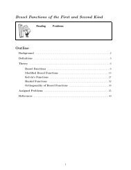
where Eλ(T) is the spectral emissive power of the real surface. As shown, the<br />
radiation emission from a real surface differs from the Planck’s distribution.<br />
( T )<br />
( T )
Fig. <strong>12</strong>-4: Comparison of the emissive power of a real surface and a blackbody.<br />
To make the radiation calculations easier, we define the following approximations:<br />
Diffuse surface: is a surface which its properties are independent of direction.<br />
Gray surface: is a surface which its properties are independent from wavelength.<br />
Therefore, the emissivity of a gray, diffuse surface is the total hemispherical (or<br />
simply the total) emissivity of that surface.<br />
A gray surface should emit as much as radiation as the real surface it represents<br />
at the same temperature:<br />
<strong>Chapter</strong> <strong>12</strong>, E&CE 309, Spring 2005. 6<br />
Majid Bahrami<br />
( T )<br />
∞<br />
∫ε<br />
λ<br />
0<br />
( T ) E ( T )<br />
ε =<br />
4<br />
σ T<br />
Emissivity is a strong function of temperature, see Fig. <strong>12</strong>-20 Cengel book.<br />
bλ<br />
dλ<br />
Absorptivity, Reflectivity, and Transmissivity<br />
The radiation energy incident on a surface per unit area per unit time is called<br />
irradiation, G.<br />
Absorptivity α: is the fraction of irradiation absorbed by the surface.<br />
Reflectivity ρ: is the fraction of irradiation reflected by the surface.<br />
Transmissivity τ: is the fraction of irradiation transmitted through the surface.<br />
Radiosity J: total radiation energy streaming from a surface, per unit area per unit<br />
time. It is the summation of the reflected and the emitted radiation.
<strong>Chapter</strong> <strong>12</strong>, E&CE 309, Spring 2005. 7<br />
Majid Bahrami<br />
absorptivity<br />
:<br />
reflectivity<br />
:<br />
transmissivity<br />
:<br />
absorbed radiation Gabs<br />
α =<br />
=<br />
incident radiation G<br />
reflected radiation Gref<br />
ρ =<br />
=<br />
incident radiation G<br />
transmitted<br />
radiation Gtr<br />
τ =<br />
=<br />
incident radiation G<br />
0 ≤ α ≤ 1<br />
0 ≤ ρ ≤ 1<br />
0 ≤ τ ≤ 1<br />
Applying the first law of thermodynamics, the sum of the absorbed, reflected, and<br />
the transmitted radiation radiations must be equal to the incident radiation:<br />
Gabs + Gref + Gtr = G<br />
Divide by G:<br />
α + ρ + τ = 1<br />
Incident<br />
radiation<br />
G, W/m 2<br />
Reflected<br />
ρG<br />
Radiosity, J<br />
(Reflected + Emitted radiation)<br />
Absorbed<br />
αG<br />
Semi-transparent<br />
material<br />
Transmitted<br />
τG<br />
Emitted radiation<br />
ε Ebλ<br />
Fig. <strong>12</strong>-5: The absorption, reflection, and transmission of irradiation by a semitransparent<br />
material.<br />
For opaque surfaces τ = 0 and thus: α + ρ = 1. The above definitions are for total<br />
hemi-spherical properties (over all direction and all frequencies). We can also<br />
define these properties in terms of their spectral counterparts:
<strong>Chapter</strong> <strong>12</strong>, E&CE 309, Spring 2005. 8<br />
Majid Bahrami<br />
G<br />
λ<br />
λ<br />
λ<br />
λ<br />
where<br />
= ρ G<br />
τ = τ<br />
λ<br />
λ<br />
λ<br />
ρ = ρ<br />
( T,<br />
λ)<br />
( T,<br />
λ)<br />
( T,<br />
λ)<br />
λ<br />
α = α<br />
thus<br />
λ<br />
λ<br />
λ<br />
+ τ G<br />
λ<br />
1 = ρ + τ + α<br />
λ<br />
λ<br />
+ α G<br />
λ<br />
λ<br />
spectral reflectivity<br />
spectral absorptivity<br />
spectral transmissivity<br />
Note that the absorptivity α is almost independent of surface temperature and it<br />
strongly depends on the temperature of the source at which the incident radiation<br />
is originating. For example α of the concrete roof is about 0.6 for solar radiation<br />
(source temperature 5762 K) and 0.9 for radiation originating from the<br />
surroundings (source temperature 300 K).<br />
Kirchhoff’s Law<br />
Consider an isothermal cavity and a surface at the same temperature T. At the<br />
steady state (equilibrium) thermal condition<br />
and radiation emitted<br />
Gabs = α G = α σ T 4<br />
Eemit = ε σ T 4<br />
Since the small body is in thermal equilibrium, Gabs = Eemit<br />
ε(T) = α(T)<br />
The total hemispherical emissivity of a surface at temperature T is equal to its total<br />
hemi-spherical absorptivity for radiation coming from a blackbody at the same<br />
temperature T. This is called the Kirchhoff’s law.<br />
T<br />
G<br />
A, ε, α<br />
Eemit<br />
Fig. <strong>12</strong>-6: Small body contained in a large isothermal cavity.<br />
The Kirchhoff’s law can be written in the spectral form:<br />
T
and in the spectral directional form<br />
<strong>Chapter</strong> <strong>12</strong>, E&CE 309, Spring 2005. 9<br />
Majid Bahrami<br />
( ) α ( T )<br />
ε =<br />
λ T λ<br />
( ) α ( T )<br />
ε , = ,<br />
λ θ T λ θ<br />
The Kirchhoff’s law makes the radiation analysis easier (ε = α), especially for<br />
opaque surfaces where ρ = 1 – α.<br />
Note that Kirchhoff’s law cannot be used when there is a large temperature<br />
difference (more than 100 K) between the surface and the source temperature.<br />
Solar <strong>Radiation</strong><br />
The solar energy reaching the edge of the earth’s atmosphere is called the solar<br />
constant:<br />
Gs = 1353 W / m 2<br />
Owing to the ellipticity of the earth’s orbit, the actual solar constant changes<br />
throughout the year within +/- 3.4%. This variation is relatively small; thus Gs is<br />
assumed to be a constant.<br />
The effective surface temperature of the sun can be estimated from the solar<br />
constant (by treating the sun as a blackbody).<br />
The solar radiation undergoes considerable attenuation as it passes through the<br />
atmosphere as a result of absorption and scattering:<br />
Absorption by the oxygen occurs in a narrow band about λ = 0.76 µm.<br />
The ozone layer absorbs ultraviolet radiation at wavelengths below λ = 0.3 µm<br />
almost completely and radiation in the range of 0.3 – 0.4 µm considerably.<br />
Absorption in the infrared region is dominated by water vapor and carbon<br />
dioxide. Dust/pollutant particles also absorb radiation at various wavelengths.<br />
As a result the solar radiation reaching the earth’s surface is about 950 W/m 2<br />
on a clear day and much less on a cloudy day, in the wavelength band 0.3 to<br />
2.5 µm.<br />
Scattering and reflection by air molecules (and other particles) are other<br />
mechanisms that attenuate the solar radiation. Oxygen and nitrogen molecules<br />
scatter radiation at short wavelengths (corresponding to violet and blue colors).<br />
That is the reason the sky seems blue!<br />
The gas molecules (mostly CO2 and H2O) and the suspended particles in the<br />
atmosphere emit radiation as well as absorbing it. It is convenient to consider the<br />
atmosphere (sky) as a blackbody at some lower temperature. This fictitious<br />
temperature is called the effective sky temperature Tsky.<br />
Gsky = σ T 4 sky<br />
Tsky = 230 K for cold clear sky
Tsky = 285 K for warm cloudy sky<br />
Using Kirchhoff’s law we can write α = ε since the temperature of the sky is on the<br />
order of the room temperature.<br />
The View Factor<br />
<strong>Radiation</strong> heat transfer between surfaces depends on the orientation of the<br />
surfaces relative to each other as well as their radiation properties and<br />
temperatures.<br />
View factor (or shape factor) is a purely geometrical parameter that accounts for<br />
the effects of orientation on radiation between surfaces.<br />
In view factor calculations, we assume uniform radiation in all directions throughout<br />
the surface, i.e., surfaces are isothermal and diffuse. Also the medium between<br />
two surfaces does not absorb, emit, or scatter radiation.<br />
Fi→j or Fij = the fraction of the radiation leaving surface i that strikes surface j<br />
directly.<br />
Note the following:<br />
The view factor ranges between zero and one.<br />
Fij = 0 indicates that two surfaces do not see each other directly. Fij = 1<br />
indicates that the surface j completely surrounds surface i.<br />
The radiation that strikes a surface does not need to be absorbed by that<br />
surface.<br />
Fii is the fraction of radiation leaving surface i that strikes itself directly. Fii = 0 for<br />
plane or convex surfaces, and Fii ≠ 0 for concave surfaces.<br />
Plane surface,<br />
Fii = 0<br />
Fig. <strong>12</strong>-7: View factor between surface and itself.<br />
Calculating view factors between surfaces are usually very complex and difficult to<br />
perform. View factors for selected geometries are given in Table <strong>12</strong>-4 and !2-5 and<br />
Figs. <strong>12</strong>-41 to <strong>12</strong>-44 in Cengel book.<br />
<strong>Chapter</strong> <strong>12</strong>, E&CE 309, Spring 2005. 10<br />
Majid Bahrami<br />
Convex surface,<br />
Fii = 0<br />
Concave surface,<br />
Fii ≠ 0
View Factor Relations<br />
<strong>Radiation</strong> analysis of an enclosure consisting of N surfaces requires the<br />
calculations of N 2 view factors. However, all of these calculations are not<br />
necessary. Once a sufficient number of view factors are available, the rest of them<br />
can be found using the following relations for view factors.<br />
The Reciprocity Rule<br />
The view factor Fij is not equal to Fji unless the areas of the two surfaces are equal.<br />
It can be shown that:<br />
<strong>Chapter</strong> <strong>12</strong>, E&CE 309, Spring 2005. 11<br />
Majid Bahrami<br />
Ai Fij =Aj Fji<br />
The Summation Rule<br />
In radiation analysis, we usually form an enclosure. The conservation of energy<br />
principle requires that the entire radiation leaving any surface i of an enclosure be<br />
intercepted by the surfaces of enclosure. Therefore,<br />
N<br />
∑ F ij<br />
j=<br />
1<br />
The summation rule can be applied to each surface of an enclosure by varying i<br />
from 1 to N (number of surfaces). Thus the summation rule gives N equations.<br />
Also reciprocity rule gives 0.5 N (N-1) additional equations. Therefore, the total<br />
number of view factors that need to be evaluated directly for an N-surface<br />
enclosure becomes<br />
N<br />
2<br />
= 1<br />
⎡ 1 ⎤ 1<br />
− ⎢N<br />
+ N<br />
⎣ 2 ⎥ N<br />
⎦ 2<br />
( N −1)<br />
= N(<br />
−1)<br />
Example <strong>12</strong>-2<br />
Determine the view factors F<strong>12</strong> and F21 for the following geometries:<br />
L = D<br />
1<br />
A2<br />
A1<br />
L<br />
2 3<br />
1) Sphere of diameter D inside a cubical box of length L = D.<br />
A1<br />
A3<br />
A2<br />
L<br />
D<br />
A1<br />
A2<br />
A3
2) Diagonal partition within a long square duct.<br />
3) End and side of a circular tube of equal length and diameter, L = D.<br />
Assumptions:<br />
Diffuse surfaces.<br />
Solution:<br />
1) sphere within a cube:<br />
By inspection, F<strong>12</strong> = 1<br />
By reciprocity and summation:<br />
<strong>Chapter</strong> <strong>12</strong>, E&CE 309, Spring 2005. <strong>12</strong><br />
Majid Bahrami<br />
F<br />
F<br />
21<br />
21<br />
=<br />
A<br />
A<br />
+ F<br />
1<br />
2<br />
22<br />
F<br />
<strong>12</strong><br />
πD<br />
=<br />
6L<br />
= 1 → F<br />
2<br />
2<br />
22<br />
π<br />
× 1 =<br />
6<br />
π<br />
= 1−<br />
6<br />
2) Partition within a square duct:<br />
From summation rule, F11 + F<strong>12</strong> + F13 = 1 where F11 = 0<br />
By symmetry F<strong>12</strong> = F13<br />
Thus, F<strong>12</strong> = 0.5.<br />
From reciprocity:<br />
F<br />
21<br />
=<br />
A<br />
A<br />
1<br />
2<br />
F<br />
<strong>12</strong><br />
=<br />
2L<br />
× 0.<br />
5 =<br />
L<br />
0.<br />
71<br />
3) Circular tube: from Fig. <strong>12</strong>-43, with r2 / L = 0.5 and L / r1 = 2, F13 ≈ 0.17.<br />
From summation rule,<br />
F11 + F<strong>12</strong> + F13 = 1 with F11 = 0, F<strong>12</strong> = 1 - F13 = 0.83<br />
From reciprocity,<br />
F<br />
The Superposition Rule<br />
21<br />
=<br />
A<br />
A<br />
1<br />
2<br />
F<br />
<strong>12</strong><br />
=<br />
2<br />
πD<br />
/ 4<br />
πDL<br />
×<br />
0.<br />
83<br />
=<br />
0.<br />
21<br />
The view factor from a surface i to a surface j is equal to the sum of the view<br />
factors from surface i to the parts of surface j.
3<br />
2<br />
The Symmetry Rule<br />
<strong>Chapter</strong> <strong>12</strong>, E&CE 309, Spring 2005. 13<br />
Majid Bahrami<br />
1<br />
=<br />
2<br />
Fig. <strong>12</strong>-8: The superposition rule for view factors.<br />
F1→(2,3) = F1→2 + F1→3<br />
Two (or more) surfaces that possess symmetry about a third surface will have<br />
identical view factors from that surface.<br />
Example: <strong>12</strong>-3<br />
Find the view factor from the base of a pyramid to each of its four sides. The base<br />
is a square and its side surfaces are isosceles triangles.<br />
From symmetry rule, we have:<br />
F<strong>12</strong> = F13 = F14 = F15<br />
Also, the summation rule yields:<br />
F11 + F<strong>12</strong> + F13 + F14 + F15 = 1<br />
Since, F11 = 0 (flat surface), we find; F<strong>12</strong> = F13 = F14 = F15 = 0.25<br />
5<br />
4<br />
1<br />
1<br />
+<br />
Pyramid in example <strong>12</strong>-2.<br />
3<br />
2<br />
3<br />
1
The Crossed-Strings Method<br />
Geometries such as channels and ducts that are very long in one direction can be<br />
considered two-dimensional (since radiation through end surfaces can be<br />
neglected). The view factor between their surfaces can be determined by crossstring<br />
method developed by H. C. Hottel, as follows:<br />
D<br />
L3<br />
A<br />
<strong>Chapter</strong> <strong>12</strong>, E&CE 309, Spring 2005. 14<br />
Majid Bahrami<br />
F i→<br />
j<br />
= ∑ ∑<br />
( crossed strings)<br />
− ( uncrossed strings)<br />
2×<br />
( string on surface i)<br />
Fig. <strong>12</strong>-9: Cross-string method.<br />
F<br />
<strong>12</strong><br />
=<br />
( L + L ) − ( L + L )<br />
Note that the surfaces do not need to be flat.<br />
<strong>Radiation</strong> <strong>Heat</strong> <strong>Transfer</strong><br />
5<br />
The analysis of radiation exchange between surfaces is complicated because of<br />
reflection. This can be simplified when surfaces are assumed to be black surfaces.<br />
The net radiation between two surfaces can be expressed as<br />
•<br />
Q<br />
•<br />
Q<br />
<strong>12</strong><br />
<strong>12</strong><br />
L5<br />
= A F<br />
1<br />
L2<br />
<strong>12</strong><br />
E<br />
− A F<br />
E<br />
b1 2 21 b2<br />
( W )<br />
6<br />
2L<br />
⎛radiation<br />
leaving surface1<br />
⎞ ⎛radiation<br />
leaving surface 2 ⎞<br />
= ⎜<br />
⎟ − ⎜<br />
⎟<br />
⎝ that directly stikes surface 2⎠<br />
⎝ that directly stikes surface1<br />
⎠<br />
Applying reciprocity A1 F<strong>12</strong> = A2 F21 yields<br />
2<br />
L1<br />
1<br />
L6<br />
•<br />
Q<br />
<strong>12</strong><br />
= A F σ<br />
1<br />
C<br />
L4<br />
B<br />
<strong>12</strong><br />
1<br />
3<br />
4 4 ( T − T ) ( W )<br />
Consider an enclosure consisting of N black surfaces maintained at specified<br />
temperatures. For each surface i, we can write<br />
1<br />
2<br />
L3<br />
4<br />
L5<br />
1<br />
L1<br />
L2<br />
2<br />
L6<br />
L4
<strong>Chapter</strong> <strong>12</strong>, E&CE 309, Spring 2005. 15<br />
Majid Bahrami<br />
•<br />
N<br />
N<br />
Q i = ∑Q<br />
ij = ∑ Ai<br />
Fijσ<br />
i j<br />
j=<br />
1<br />
•<br />
j=<br />
1<br />
4 4 ( T − T ) ( W )<br />
Using the sign convention, a negative heat transfer rate indicates that the radiation<br />
heat transfer is to surface i (heat gain).<br />
Now, we can extend this analysis to non-black surfaces. It is common to assume<br />
that the surfaces are opaque, diffuse, and gray. Also, surfaces are considered to<br />
be isothermal. Also the fluid inside the cavity is not participating in the radiation.<br />
Radiosity J is the total radiation energy streaming from a surface, per unit area per<br />
unit time. It is the summation of the reflected and the emitted radiation.<br />
For a surface i that is gray and opaque (εi = αi and αi + ρi = 1), the Radiosity can be<br />
expressed as<br />
J<br />
J<br />
J<br />
i<br />
i<br />
i<br />
= ε E<br />
i<br />
= ε E<br />
i<br />
= ε E<br />
i<br />
bi<br />
bi<br />
bi<br />
+ ρ G<br />
+<br />
i<br />
i<br />
2<br />
( 1−<br />
ε ) G ( W / m )<br />
= σT<br />
4<br />
i<br />
i<br />
i<br />
( for a blackbody)<br />
Note that the radiosity of a blackbody is equal to its emissive power.<br />
Using an energy balance, the net rate of radiation heat transfer from a surface i of<br />
surface area Ai can be expressed as<br />
•<br />
Q<br />
•<br />
Q<br />
i<br />
i<br />
= A<br />
i<br />
( J − G ) ( W )<br />
i<br />
⎛<br />
= Ai<br />
⎜ J<br />
⎝<br />
i<br />
i<br />
J i − ε i E<br />
−<br />
1−<br />
ε<br />
i<br />
bi<br />
⎞ Aiε<br />
i<br />
⎟ =<br />
⎠ 1−<br />
ε i<br />
( E − J )<br />
In electrical analogy to Ohm’s law, a thermal resistance can be defined as<br />
• Ebi<br />
− J i<br />
Q i =<br />
Ri<br />
1−<br />
ε i<br />
Ri<br />
=<br />
A ε<br />
where Ri is called the surface resistance to radiation.<br />
Surface i<br />
Ebi<br />
Fig. <strong>12</strong>-10: Surface resistance to radiation.<br />
i<br />
i<br />
Q • i<br />
bi<br />
i<br />
Ji
Note that the surface resistance to radiation for a blackbody is zero.<br />
For insulated or adiabatic surfaces, the net heat transfer through them is zero. In<br />
this cases, the surface is called reradiating surface. There is no net heat transfer to<br />
a reradiating surface.<br />
Net <strong>Radiation</strong> between Two Surfaces<br />
Consider two diffuse, gray, and opaque surfaces of arbitrary shape maintained at<br />
uniform temperatures. The net rate of radiation heat transfer from surface i to<br />
surface j can be expressed<br />
<strong>Chapter</strong> <strong>12</strong>, E&CE 309, Spring 2005. 16<br />
Majid Bahrami<br />
•<br />
Q<br />
•<br />
Q<br />
ij<br />
ij<br />
= A J<br />
= A F<br />
i<br />
i<br />
i<br />
ij<br />
F<br />
ij<br />
− A<br />
J<br />
Applying reciprocity<br />
F<br />
( J − J ) ( W )<br />
i<br />
j<br />
j<br />
j<br />
ji<br />
( W )<br />
In analogy with Ohm’s law, a resistance can be defined as<br />
•<br />
Q<br />
R<br />
ij<br />
ij<br />
J i − J<br />
=<br />
Rij<br />
1<br />
=<br />
A F<br />
where Rij is called the space resistance to radiation.<br />
Ebi<br />
Ri<br />
Ji<br />
Fig. <strong>12</strong>-11: Electrical network, surface and space resistances.<br />
In an N-surface enclosure, the conservation of energy principle requires that the<br />
net heat transfer from surface i to be equal to the sum of the net heat transfers<br />
from i to each of the N surfaces of the enclosure.<br />
N • N J<br />
Q i = ∑Q<br />
ij = ∑<br />
•<br />
i −<br />
j=<br />
1<br />
Q • ij<br />
Rij<br />
Surface i Surface j<br />
i<br />
ij<br />
R<br />
j= 1 ij<br />
We have already derived a relationship for the net radiation from a surface<br />
j<br />
J<br />
j<br />
Jj<br />
Rj<br />
( W )<br />
Ebj
Combining these two relationships gives:<br />
<strong>Chapter</strong> <strong>12</strong>, E&CE 309, Spring 2005. 17<br />
Majid Bahrami<br />
•<br />
Q<br />
i<br />
i<br />
=<br />
E<br />
Ebi<br />
− J i<br />
=<br />
R<br />
bi<br />
− J<br />
R<br />
i<br />
J<br />
i<br />
− J<br />
N<br />
i<br />
∑<br />
j= 1 Rij<br />
Method of Solving <strong>Radiation</strong> Problem<br />
In radiation problems, either the temperature or the net rate of heat transfer must<br />
be given for each of the surfaces to obtain a unique solution for the unknown<br />
surface temperature and heat transfer rates.<br />
We use the network method which is based on the electrical network analogy.<br />
The following steps should be taken:<br />
1. Form an enclosure; consider fictitious surface(s) for openings, room, etc.<br />
2. Draw a surface resistance associated with each surface of the enclosure<br />
3. Connect the surface resistances with space resistances<br />
4. Solve the radiations problem (radiosities) by treating it as an electrical<br />
network problem.<br />
Note that this method is not practical for enclosures with more than 4 surfaces.<br />
Example <strong>12</strong>-4: Hot Plates in Room<br />
Two parallel plates 0.5 by 1.0 m are spaced 0.5 m apart. One plate is maintained<br />
at 1000°C and the other at 500°C. The emissivities of the plates are 0.2 and 0.5,<br />
respectively. The plates are located in a very large room, the walls of which are<br />
maintained at 27°C. The plates exchange heat with each other and with the room,<br />
but only the plate surfaces facing each other are to be considered in the analysis.<br />
Find the net heat transfer rate to each plate and the room; neglect other modes of<br />
heat transfer, i.e., conduction and convection.<br />
j<br />
( W )<br />
( W )<br />
Assumptions:<br />
Diffuse, gray, and opaque surfaces and steady-state heat transfer.<br />
Solution:<br />
This is a three-body problem, the two plates and room. The radiation network is<br />
shown below.
where,<br />
<strong>Chapter</strong> <strong>12</strong>, E&CE 309, Spring 2005. 18<br />
Majid Bahrami<br />
T1 =1000°C<br />
T2 =1000°C<br />
Fig. <strong>12</strong>-<strong>12</strong>: Schematic for Problem <strong>12</strong>-4<br />
T1 = 1000°C = <strong>12</strong>73 K A1 = A2 = 0.5 m2<br />
T2 = 500°C = 773 K T3 = 27°C = 300 K<br />
ε1 = 0.2 ε2 = 0.5<br />
Eb1<br />
Q • 1<br />
1<br />
2<br />
R1<br />
J1<br />
R13<br />
Fig. <strong>12</strong>-<strong>12</strong>: Thermal network for Problem <strong>12</strong>-4.<br />
We can assume that the room is a blackbody, since its surface resistance is<br />
negligible:<br />
R<br />
3<br />
Q • 3<br />
1−<br />
ε 3<br />
= ≈ 0 A3<br />
>><br />
A ε<br />
From Fig. <strong>12</strong>-41 in Cengel book, the shape factor F<strong>12</strong> = 0.285<br />
Using reciprocity and A1 = A2, F<strong>12</strong> = F21 = 0.285<br />
Applying summation rule<br />
F11 + F<strong>12</strong> + F13 = 1<br />
3<br />
1.0 m<br />
R<strong>12</strong><br />
3<br />
0.5 m<br />
J2<br />
R23<br />
Eb3 = J3 = σT 4 3<br />
R2<br />
0.5 m<br />
3 room<br />
at 27°C<br />
Q • 2<br />
Eb2
Since F11 = 0 (flat plate), F13 = 1 - 0.285 = 0.715<br />
Finally, from symmetry F23 = F13 = 0.715<br />
The surface resistances are<br />
Space resistances are<br />
<strong>Chapter</strong> <strong>12</strong>, E&CE 309, Spring 2005. 19<br />
Majid Bahrami<br />
R<br />
R<br />
R<br />
<strong>12</strong><br />
23<br />
13<br />
1−<br />
ε1<br />
R1<br />
= =<br />
A ε<br />
1<br />
2<br />
1<br />
1−<br />
ε 2<br />
R2<br />
= =<br />
A ε<br />
1<br />
=<br />
A F<br />
1<br />
2<br />
1<br />
<strong>12</strong><br />
1<br />
=<br />
A F<br />
1<br />
=<br />
A F<br />
23<br />
13<br />
2<br />
=<br />
=<br />
=<br />
1−<br />
2 ( 0.<br />
2)(<br />
0.<br />
5m<br />
)<br />
1−<br />
0.<br />
2<br />
0.<br />
5<br />
2 ( 0.<br />
5)(<br />
0.<br />
5m<br />
)<br />
1<br />
2<br />
( 0.<br />
285)(<br />
0.<br />
5m<br />
)<br />
1<br />
=<br />
2<br />
( 0.<br />
715)(<br />
0.<br />
5m<br />
)<br />
1<br />
2<br />
( 0.<br />
175)(<br />
0.<br />
5m<br />
)<br />
=<br />
=<br />
=<br />
8.<br />
0<br />
=<br />
2.<br />
0<br />
7.<br />
018<br />
2.<br />
797<br />
2.<br />
797<br />
We need to find the radiosity for surface 1 and 2 only, since surface 3 is a<br />
blackbody, J3 = Eb3 = σT 4 3<br />
For node J1:<br />
For node J2:<br />
where<br />
E<br />
E<br />
J<br />
Eb1 Eb2 b1<br />
b2<br />
3<br />
− J<br />
R<br />
1<br />
− J<br />
R<br />
2<br />
b3<br />
1<br />
2<br />
= σT<br />
= E<br />
4<br />
1<br />
= σT<br />
4<br />
2<br />
J 2 − J<br />
+<br />
R<br />
<strong>12</strong><br />
J1<br />
− J<br />
+<br />
R<br />
= σT<br />
4<br />
3<br />
<strong>12</strong><br />
1<br />
2<br />
= 148.<br />
87<br />
=<br />
20.<br />
241<br />
=<br />
J 3 − J<br />
+<br />
R<br />
13<br />
23<br />
1<br />
J 3 − J<br />
+<br />
R<br />
0.<br />
4592<br />
kW / m<br />
2<br />
2<br />
kW / m<br />
2<br />
= 0<br />
= 0<br />
kW / m<br />
Substituting values and solving two equations, one finds:<br />
J1 = 33.469 kW/m2 and J2 = 15.054 kW/m2<br />
The total heat loss by plate 1 is:<br />
•<br />
Q<br />
•<br />
Q<br />
1<br />
2<br />
=<br />
=<br />
E<br />
E<br />
b1<br />
− J<br />
R<br />
b2<br />
1<br />
− J<br />
R<br />
2<br />
1<br />
2<br />
= 14.<br />
425<br />
=<br />
2.<br />
594<br />
kW<br />
kW<br />
2
The total radiation received by the room is<br />
<strong>Chapter</strong> <strong>12</strong>, E&CE 309, Spring 2005. 20<br />
Majid Bahrami<br />
• J1<br />
− J 3 J 2 − J 3<br />
Q 3 = + = 17.<br />
020<br />
R R<br />
Note that from an energy balance, we must have:<br />
13<br />
•<br />
Q<br />
3<br />
•<br />
1<br />
23<br />
•<br />
2<br />
= Q + Q<br />
kW