Hydrastart Couplings
Hydrastart Couplings
Hydrastart Couplings

You also want an ePaper? Increase the reach of your titles
YUMPU automatically turns print PDFs into web optimized ePapers that Google loves.
<strong>Hydrastart</strong> <strong>Couplings</strong><br />
www.renold.com
Strength<br />
Strength through Service<br />
through Service<br />
Renold Gears has been manufacturing high quality, high specification gear units for over<br />
Renold Gears has been manufacturing high quality, high specification gear units for over<br />
100 Renold years Gears and has hasbeen always manufacturing been at the leading high quality, edge of high gear specification technologygear withunits innovative for over<br />
100 years and has always been at the leading edge of gear technology with innovative<br />
100 products yearsand and power has always transmission been at solutions. the leading edge of gear technology with innovative<br />
products and power transmission solutions.<br />
products and power transmission solutions.<br />
Interchangeability<br />
Interchangeability<br />
Interchangeability<br />
Many of the products from<br />
Many of the products from<br />
Many Renoldof Gears the products are dimensionally from<br />
Renold Gears are dimensionally<br />
interchangeable Renold Gears arewith dimensionally other<br />
interchangeable with other<br />
interchangeable manufacturers gear withunits, other<br />
manufacturers gear units,<br />
allowing manufacturers a trouble gear free units,<br />
allowing a trouble free<br />
replacement allowing a trouble of gearboxes, free<br />
replacement of gearboxes,<br />
replacement in most casesof upgrading gearboxes, the<br />
in most cases upgrading the<br />
capacity in most cases through upgrading state of the<br />
capacity through state of the<br />
capacity art technology through and state materials. of the<br />
art technology and materials.<br />
art technology and materials.<br />
Custom<br />
Custom<br />
Custom<br />
Made<br />
Made<br />
Made<br />
Renold Gears is unique in it’s<br />
Renold Gears is unique in it’s<br />
ability Renoldto Gears offeriscustom uniquemade in it’s<br />
ability to offer custom made<br />
ability products to designed offer custom to meet made<br />
products designed to meet<br />
products customers designed exactingto<br />
meet<br />
customers exacting<br />
requirements customers exacting without<br />
requirements without<br />
requirements compromise on without availability and<br />
compromise on availability and<br />
cost. compromise From complete on availability package and<br />
cost. From complete package<br />
solutions cost. Fromtocomplete individual package precision<br />
solutions to individual precision<br />
replacement solutions to individual gears, all can precision be<br />
replacement gears, all can be<br />
tailor replacement made togears, meetall specific can be<br />
tailor made to meet specific<br />
tailor applicational made torequirements. meet specific<br />
applicational requirements.<br />
applicational requirements.<br />
Available<br />
Available<br />
Available<br />
The most popular ranges of<br />
The most popular ranges of<br />
The gearboxes most popular are available ranges from of<br />
gearboxes are available from<br />
gearboxes local distribution are available stock, from backed<br />
local distribution stock, backed<br />
up local bydistribution extensive stocks stock, from backed our<br />
up by extensive stocks from our<br />
manufacturing up by extensiveplant stocksinfrom the UK. our<br />
manufacturing plant in the UK.<br />
manufacturing plant in the UK.<br />
Superior Gear & Coupling Technology<br />
Superior Gear & Coupling Technology<br />
Superior Gear & Coupling Technology<br />
www.renold.com<br />
www.renold.com<br />
www.renold.com
Contents<br />
Page No<br />
Renold Gears inside front cover<br />
Coupling Selection Guide 02<br />
Load Classification by Application 03<br />
Service Factors and Selection 04<br />
Key and Keyway Dimensions 05<br />
<strong>Hydrastart</strong> Fluid Coupling 06<br />
Operating Principles 07<br />
Delayed Fill 08<br />
‘Soft’ Starting 09<br />
<strong>Hydrastart</strong> Selection Chart 10<br />
Coupling Rating Tables 11<br />
Standard Available Options 12<br />
Overload Protection 13<br />
<strong>Hydrastart</strong> Pinflex Coupling – Dimensions (mm) 14<br />
<strong>Hydrastart</strong> Pinflex Coupling – With Brake Attachment 15<br />
<strong>Hydrastart</strong> Gearflex Coupling – Dimensions (mm) 16<br />
<strong>Hydrastart</strong> Pulley – Dimensions (mm) 17<br />
<strong>Hydrastart</strong> Drop-in 18<br />
Renold Chain inside back cover<br />
Page 01
Page 02<br />
Coupling Selection Guide<br />
At installation all couplings should be aligned as near to Ø<br />
perfect as possible.<br />
1. Angular<br />
Angular misalignment is present when the shaft axes are<br />
inclined one to the other. Its magnitude can be measured at the<br />
coupling faces.<br />
2. Parallel Offset<br />
Axial misalignment is present when the axes of the driving and<br />
driven shafts are parallel but laterally displaced.<br />
3. End float (axial)<br />
End float is the ability to accommodate a relative axial<br />
displacement of the connected shafts; achieved by sliding<br />
members or flexing of resilient components.<br />
4. Torsional flexibility<br />
Torsional flexibility is a design feature necessary to permit shock<br />
and impulsive loadings to be suitably dampened. It is achieved<br />
by the provision of a flexible medium such as rubber, springs,<br />
etc., between the two halves of the coupling.<br />
Selection<br />
In order to select the correct type and size of coupling, the<br />
following basic information should be known:<br />
Power to be transmitted<br />
(a) Normal.<br />
(b) Maximum.<br />
(c) Whether continuous or intermittent.<br />
Characteristics of the drive<br />
(a) Type of prime mover and associated equipment.<br />
(b) Degree of impulsiveness of driven load.<br />
<strong>Hydrastart</strong> <strong>Couplings</strong><br />
Ø<br />
Ø<br />
Angular<br />
O<br />
O<br />
Parallel offset<br />
Flexible <strong>Couplings</strong> should be used ƒ to accommodate any combination of misalignment conditions<br />
described below.<br />
ƒ<br />
Ø<br />
Ø<br />
O<br />
Ø<br />
O<br />
End float<br />
ƒ<br />
Torsional flexibility<br />
Speed in revolutions per minute<br />
(a) At which normal power is transmitted.<br />
(b) At which maximum power is transmitted.<br />
(c) Maximum speed.<br />
Dimensions of shafts to be connected<br />
(a) Actual diameter.<br />
(b) Length of shaft extension.<br />
(c) Full keyway particulars.<br />
Selection<br />
When the input drive is not steady (i.e. not from an electric<br />
motor), and/or the driven load is impulsive, the actual power is<br />
multiplied by a Service Factor from the Table 2 (page 13).<br />
Selection Procedure<br />
1. Nominal power in kW to be transmitted = K.<br />
2. Select appropriate load classification from Table 1, denoted<br />
as either S, M or H.<br />
3. From Table 2, establish Service Factor(s) to be applied, taking<br />
into account hours of operation/day and prime mover = fD.<br />
4. From Table 3 select factor for the required frequency of<br />
starts/hr = fS.<br />
5. Selection Power Ks = K x fD x fS<br />
ƒ<br />
6. Equivalent power at 100 RPM = Ks x 100<br />
RPM<br />
7. Check that coupling selected will accept the required shaft<br />
diameters. Should shaft diameter exceed maximum permissible,<br />
then re-select using next larger size of coupling.<br />
Ø<br />
Ø
Table 1<br />
Agitators<br />
Pure liquids S<br />
Liquids and solids M<br />
Liquids - variable density<br />
Blowers<br />
M<br />
Centrifugal S<br />
Lobe M<br />
Vane<br />
Brewing and distilling<br />
S<br />
Bottling machinery S<br />
Brew kettles - continuous duty S<br />
Cookers - continuous duty S<br />
Mash tubs - continuous duty S<br />
Scale hopper - frequent starts M<br />
Can filling machines S<br />
Cane knives (1) M<br />
Car dumpers H<br />
Car pullers M<br />
Clarifiers S<br />
Classifiers<br />
Clay working machinery<br />
M<br />
Brick press H<br />
Briquette machine H<br />
Clay working machinery M<br />
Pug mill<br />
Compressors<br />
M<br />
Centrifugal S<br />
Lobe M<br />
Reciprocating - multi-cylinder M<br />
Reciprocating - single cylinder<br />
Conveyors - uniformly loaded or fed<br />
H<br />
Apron S<br />
Assembly S<br />
Belt S<br />
Bucket S<br />
Chain S<br />
Flight S<br />
Oven S<br />
Screw<br />
Conveyors - heavy duty<br />
not uniformly fed<br />
S<br />
Apron M<br />
Assembly M<br />
Belt M<br />
Bucket M<br />
Chain M<br />
Flight M<br />
Live roll *<br />
Oven M<br />
Reciprocating H<br />
Screw M<br />
Shaker<br />
Crane Drives - not dry dock<br />
H<br />
Main hoists S<br />
Bridge travel *<br />
Trolley travel<br />
Crushers<br />
*<br />
Ore H<br />
Stone H<br />
Sugar (1)<br />
Dredges<br />
M<br />
Cable reels M<br />
Conveyors M<br />
Cutter head drives H<br />
Jig drives H<br />
Manoeuvring winches M<br />
Pumps M<br />
Screen drive H<br />
Stackers<br />
Utility winches<br />
M<br />
M<br />
Key<br />
S = Steady<br />
M = Medium Impulsive<br />
H = Highly Impulsive<br />
* = Refer to Renold<br />
Dry dock cranes<br />
Main hoist (2)<br />
Auxiliary hoist (2)<br />
Boom, luffing (2)<br />
Rotating, swing or slew (3)<br />
Tracking, drive wheels (4)<br />
Elevators<br />
Bucket - uniform load S<br />
Bucket - heavy load M<br />
Bucket - continuous S<br />
Centrifugal discharge S<br />
Escalators S<br />
Freight M<br />
Gravity discharge S<br />
Man lifts *<br />
Passenger *<br />
Extruders (plastic)<br />
Film S<br />
Sheet S<br />
Coating S<br />
Rods S<br />
Tubing S<br />
Blow moulders M<br />
Pre-plasticiers M<br />
Fans<br />
Centrifugal S<br />
Cooling towers<br />
Induced draft *<br />
Forced draft *<br />
Induced draft M<br />
Large, mine etc. M<br />
Large, industrial M<br />
Light, small diameter S<br />
Feeders<br />
Apron M<br />
Belt M<br />
Disc S<br />
Reciprocating H<br />
Screw M<br />
Food industry<br />
Beef slicer M<br />
Cereal cooker S<br />
Dough mixer M<br />
Meat grinder M<br />
Generators - not welding S<br />
Hammer mills H<br />
Hoists<br />
Heavy duty H<br />
Medium duty M<br />
Skip hoist M<br />
Laundry<br />
Washers - reversing M<br />
Tumblers M<br />
Line shafts<br />
Driving processing equipment M<br />
Light S<br />
Other line shafts S<br />
Lumber industry<br />
Barkers, hydraulic, mechanical M<br />
Burner conveyor M<br />
Chain saw and drag saw H<br />
Chain transfer H<br />
Craneway transfer H<br />
De-barking drum H<br />
Edger feed M<br />
Gang feed M<br />
Green chain M<br />
Live rolls H<br />
Log deck H<br />
Log haul - incline H<br />
Log haul - well type H<br />
Log turning device H<br />
Main log conveyor H<br />
Off bearing rolls M<br />
(1) = Select on 24 hours per day service factor only.<br />
(2) = Use service factor of 1.00 for any duration of service.<br />
(3) = Use service factor of 1.25 for any duration of service.<br />
(4) = Use service factor of 1.50 for any duration of service.<br />
Page 03<br />
Load Classification by Application<br />
Planer feed chains M<br />
Planer floor chains M<br />
Planer tilting hoist M<br />
Re-saw merry-go-round conveyor M<br />
Roll cases H<br />
Slab conveyor H<br />
Small waste conveyor-belt S<br />
Small waste conveyor-chain M<br />
Sorting table M<br />
Tipple hoist conveyor M<br />
Tipple hoist drive M<br />
Transfer conveyors M<br />
Transfer rolls M<br />
Tray drive M<br />
Trimmer feed M<br />
Waste conveyor M<br />
Machine tools<br />
Bending roll M<br />
Punch press - gear driven H<br />
Notching press - belt drive *<br />
Plate planners H<br />
Tapping machine H<br />
Other machine tools<br />
Main drives M<br />
Auxiliary drives S<br />
Metal mills<br />
Drawn bench carriage and<br />
main drive M<br />
Pinch, dryer and scrubber<br />
rolls, reversing *<br />
Slitters M<br />
Table conveyors nonreversing<br />
group drives M<br />
Individual drives H<br />
Reversing *<br />
Wire drawing and flattening machine M<br />
Wire winding machine M<br />
Mills, rotary type<br />
Ball (1) M<br />
Cement kilns (1) M<br />
Dryers and coolers (1) M<br />
Kilns other than cement M<br />
Pebble (1) M<br />
Rod, plain & wedge bar (1) M<br />
Tumbling barrels H<br />
Mixers<br />
Concrete mixers continuous M<br />
Concrete mixers intermittent M<br />
Constant density S<br />
Variable density M<br />
Oil industry<br />
Chillers M<br />
Oil well pumping *<br />
Paraffin filter press M<br />
Rotary kilns M<br />
Paper mills<br />
Agitators (mixers) M<br />
Barker - auxiliaries hydraulic M<br />
Barker - mechanical H<br />
Barking drum H<br />
Beater and pulper M<br />
Bleacher S<br />
Calenders M<br />
Calenders - super H<br />
Converting machine except<br />
cutters, platers M<br />
Conveyors S<br />
Couch M<br />
Cutters, platers H<br />
Cylinders M<br />
Dryers M<br />
Fell stretcher M<br />
Fell whipper H<br />
Jordans M<br />
Log haul H<br />
Note<br />
Presses M<br />
Pulp machine reel M<br />
Stock chest M<br />
Suction roll M<br />
Washers and thickeners M<br />
Winders M<br />
Printing presses *<br />
Pullers<br />
Barge haul H<br />
Pumps<br />
Centrifugal S<br />
Proportioning M<br />
Reciprocating<br />
single acting: 3 or more cylinders M<br />
double acting: 2 or more cylinders M<br />
single acting: 1 or 2 cylinders *<br />
double acting: single cylinder *<br />
Rotary - gear type S<br />
Rotary - lobe, vane S<br />
Rubber and plastics industries<br />
Crackers (1) H<br />
Laboratory equipment M<br />
Mixed mills (1) H<br />
Refiners (1) M<br />
Rubber calenders (1) M<br />
Rubber mill, 2 on line (1) M<br />
Rubber mill, 3 on line (1) S<br />
Sheeter (1) M<br />
Tyre building machines *<br />
Tyre and tube press openers *<br />
Tubers and strainers (1) M<br />
Warming mills (1) M<br />
Sand muller M<br />
Screens<br />
Air washing S<br />
Rotary, stone or gravel M<br />
Travelling water intake S<br />
Sewage disposal equipment<br />
Bar screens S<br />
Chemical feeders S<br />
Collectors S<br />
Dewatering screws M<br />
Scum breakers M<br />
Slow or rapid mixers M<br />
Thickeners M<br />
Vacuum filters M<br />
Slab pushers M<br />
Steering gear *<br />
Stokers S<br />
Sugar industry<br />
Cane knives (1) M<br />
Crushers (1) M<br />
Mills (1) M<br />
Textile industry<br />
Batchers M<br />
Calenders M<br />
Cards M<br />
Dry cans M<br />
Dryers M<br />
Dyeing machinery M<br />
Looms M<br />
Mangles M<br />
Nappers M<br />
Pads M<br />
Range drives *<br />
Slashers M<br />
Soapers M<br />
Spinners M<br />
Tenter frames M<br />
Washers M<br />
Winders M<br />
Windlass *<br />
Machinery characteristics and service factors listed in this catalogue are<br />
a guide only. Some applications (e.g. constant power) may require special<br />
considerations. Please consult Renold.<br />
www.renold.com
Page 04<br />
Service Factors and Selection<br />
Table 2 Service Factor (fD)<br />
Example of Selection<br />
Coupling is required to transmit 7.5kW at 1440 RPM to connect<br />
an electric motor to a gear box driving a chain conveyor running<br />
for 18 hours/day and starting 15 times/hour. Shaft diameters<br />
/55mm respectively.<br />
K = 7.5kW<br />
Prime mover<br />
From Table 1 Load Classification = M (medium impulsive)<br />
From Table 2 Service Factor fD = 1.5<br />
From Table 3 fS = 1.2<br />
Therefore selection kW is:-<br />
Ks = K x fD x fS<br />
= 7.5 x 1.5 x 1.2<br />
= 13.5 kW<br />
Equivalent power at 100 RPM = Ks x 100<br />
RPM<br />
<strong>Hydrastart</strong> <strong>Couplings</strong><br />
= 13.5 x 100<br />
1440<br />
= 0.9375kW @ 100RPM<br />
From page 17 selection is RSC110 (644911)<br />
(maximum bore 55 mm).<br />
Driven machinery characteristics<br />
(Drive input) Duration service Steady load Medium impulsive Highly impulsive<br />
hours/day<br />
Electric, air & hydraulic Intermittent – 3hrs/day max 0.90 1.00 1.50<br />
Motors or steam turbine 3 - 10 1.00 1.25 1.75<br />
(Steady input) over 10 1.25 1.50 2.00<br />
Multi-cylinder I.C. engine Intermittent – 3hrs/day max 1.00 1.25 1.75<br />
(Medium impulsive input) 3 - 10 1.25 1.50 2.00<br />
over 10 1.50 1.75 2.25<br />
Single-cylinder I.C. engine Intermittent - 3hrs/day max 1.25 1.50 2.00<br />
(Highly impulsive input) 3 - 10 1.50 1.75 2.25<br />
over 10 1.75 2.00 2.50<br />
Table 3 Factor for Starts/Hour(fS)<br />
No of starts per hour 0-1 1-30 30-60 60-<br />
!<br />
WARNING<br />
Factor 1,0 1,2 1,3 1,5<br />
It is the responsibility of the system designer<br />
to ensure that the application of the coupling<br />
does not endanger the other constituent<br />
components in the system. Service factors<br />
given are an initial selection guide.<br />
Key Stress<br />
1. Permissible key stress = 70N/mm 2<br />
2. Nominal torque TKM = K x 9550 / RPM Nm<br />
3. Force at key F = TKM /r<br />
4. Shaft Rad r. metres<br />
5. Key area A = J x HUB length mm<br />
(Obtain from relevant catalogue page).<br />
6. Key stress fk = F/A N/mm 2<br />
7. If resultant stress is less than 70 N/mm 2 key stress is<br />
acceptable.<br />
If resultant fk is greater than 70, consider either two keyways<br />
or extending hub length.<br />
8. Example:<br />
TKM = 7.5 x 9550/1440 = 49.7Nm<br />
r = 55/2 = 27.5mm ÷ 1000 = 0.0275m<br />
F = 49.7/0.0275 = 1741N<br />
A = 16 x 45 = 720mm 2<br />
fk = 1741/720 = 2.4M/mm 2<br />
Selection is therefore good.<br />
For operation above 80% of the declared maximum coupling<br />
speed it is recommended that the coupling is dynamically<br />
balanced.<br />
!<br />
WARNING<br />
Rotating equipment must be provided with<br />
a suitable guard before operating or injury<br />
may result.
[ fig 01 ]<br />
L<br />
L<br />
Metric (mm)<br />
J<br />
Keyways comply with BS4235: Part 1: 1972<br />
Shaft dia. Key & keyway<br />
Over Incl. J K L<br />
6 8 2 2 1.0<br />
8 10 3 3 1.4<br />
10 12 4 4 1.8<br />
12 17 5 5 2.3<br />
17 22 6 6 2.8<br />
22 30 8 7 3.3<br />
30 38 10 8 3.3<br />
38 44 12 8 3.3<br />
44 50 14 9 3.8<br />
50 58 16 10 4.3<br />
58 65 18 11 4.4<br />
65 75 20 12 4.9<br />
75 85 22 14 5.4<br />
85 95 25 14 5.4<br />
95 110 28 16 6.4<br />
110 130 32 18 7.4<br />
130 150 36 20 8.4<br />
150 170 40 22 9.4<br />
170 200 45 25 10.4<br />
200 230 50 28 11.4<br />
J<br />
K<br />
K<br />
Imperial (inches)<br />
Page 05<br />
Key and Keyway Dimensions<br />
Keyways comply with BS46: Part 1: 1958<br />
Shaft dia. Key & keyway<br />
page 8 A/W’s<br />
Over Incl. J K L<br />
0.25 0.05 0.125 0.125 0.060<br />
0.50 0.75 0.187 0.187 0.088<br />
0.75 1.00 0.250 0.250 0.115<br />
1.00 1.25 0.312 0.250 0.090<br />
1.25 1.50 0.375 0.250 0.085<br />
1.50 1.75 0.437 0.312 0.112<br />
1.75 2.00 0.500 0.312 0.108<br />
2.00 2.50 0.625 0.437 0.162<br />
2.50 3.00 0.750 0.500 0.185<br />
3.00 3.50 0.875 0.625 0.245<br />
3.50 4.00 1.000 0.750 0.293<br />
4.00 5.00 1.250 0.875 0.340<br />
5.00 6.00 1.500 1.000 0.384<br />
Keyway dimensions [ fig 01 ]<br />
Parallel keyways are supplied unless customer states otherwise.<br />
www.renold.com
Page 06<br />
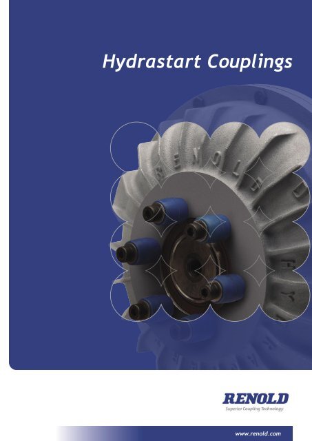
<strong>Hydrastart</strong> Fluid Coupling<br />
A fluid coupling suitable for soft starting high inertia machinery with reduced current demand,<br />
controlled acceleration and torque with motor overload protection.<br />
Coupling capacity<br />
• Maximum power @ 1500RPM 600kW<br />
• Maximum torque: 3500RPM<br />
Features and benefits<br />
• High inertia controlled torque to<br />
700 kW.<br />
• Soft start - motor starts on low load.<br />
• Allows use of standard squirrel cage<br />
motors.<br />
<strong>Hydrastart</strong> <strong>Couplings</strong><br />
• Overload protection - fusible plug<br />
safeguards equipment.<br />
• Dampens torsional vibration,<br />
reducing mechanical stress - extends<br />
machine life.<br />
• Delay fill version - extends<br />
acceleration time and reduces startup<br />
torque.<br />
• Can match load and speed on multi<br />
drives.<br />
• Energy saving through reduced<br />
current demand at start-up.<br />
• Coupling and V pulley types - design<br />
flexibility.
OUTER Outer COVERS covers<br />
DRIVEN Driven IMPELLER impeller (B) (B)<br />
(OR TURBINE) (or turbine)<br />
INPUT Input OUTPUT Output<br />
The coupling is partially filled with hydraulic oil to a level suitable<br />
for the absorbed power of the application and the acceleration<br />
characteristics of the driven machinery. The optimum oil fill is that<br />
which just allows the driven machine to accelerate from rest, thus<br />
providing the best drive overload protection.<br />
Power is supplied to the input side of the coupling by either an<br />
electric motor or diesel engine. This causes the driving impeller<br />
(A) [ fig 07 ] to be rotated at motor speed, oil is thrown outwards<br />
by centrifugal force. The flow of oil is directed across the blades<br />
of the impeller towards the opposing turbine (B). Kinetic energy is<br />
absorbed by the turbine and translated into torque, which is always<br />
equal to the input torque and produces rotation of the output<br />
member (in the same direction as the driver).<br />
The low resistance of the impeller at start up allows the motor<br />
to quickly accelerate to full speed. The driven load accelerates<br />
smoothly to within a small percentage of the motor speed.<br />
This speed difference is referred to as slip and must always be<br />
present for the successful operation of a fluid coupling.<br />
Typical values of slip will vary between 2% (large power) and 6%<br />
(small power).<br />
DRIVING IMPELLER (A)<br />
Driving<br />
(OR PUMP)<br />
impeller (A)<br />
(or pump)<br />
[ fig 07 ]<br />
All hydraulic couplings can be driven in either directions of<br />
rotation.<br />
The input and output positions shown are standard, but the input<br />
can be from either side of the coupling.<br />
The standard drive arrangement allows the outer cover to be<br />
rotated whilst at rest to facilitate oil filling.<br />
However, if a brake drum or disc brake is fitted, the brake should<br />
be at the coupling output. See page 67.<br />
To calculate slip %<br />
(Input speed - output speed) x 100<br />
Input speed<br />
Page 07<br />
Operating Principles<br />
www.renold.com
Page 08<br />
Delayed Fill<br />
<strong>Hydrastart</strong> Delayed Fill Chamber (Type HS...R)<br />
HydraStart (constant fill) hydraulic couplings having a maximum<br />
oil fill will limit the starting torque to approximately 200% of<br />
nominal torque. It is possible to reduce this figure by reducing<br />
the quantity of oil in the circuit.<br />
The disadvantage of this method is that it produces increased<br />
slip and higher operating temperatures. To overcome these<br />
At rest [ fig 08 ]<br />
[ fig 08 ]<br />
With the drive at rest, oil drains from<br />
the working circuit into the delay<br />
chamber.<br />
!<br />
CAUTION<br />
<strong>Hydrastart</strong> <strong>Couplings</strong><br />
The outer case of the <strong>Hydrastart</strong> coupling<br />
can become hot during operation. Do not<br />
touch the coupling or a burn may result.<br />
[ fig 09 ] [ fig 10 ]<br />
Accelerating [ fig 09 ]<br />
At start up the coupling will transmit<br />
limited torque, allowing the motor to<br />
reach rated speed quickly. Oil flows<br />
from the chamber to the working<br />
circuit proportionally to the speed.<br />
problems a delay fill chamber is available on sizes HS8 and<br />
above.<br />
This chamber is a modular option and allows a calibrated oil<br />
feed into the working circuit. In this way, starting torque can be<br />
reduced whilst minimising slip under normal running.<br />
!<br />
CAUTION<br />
Running [ fig 10 ]<br />
When the coupling achieves its rated<br />
speed, almost all of the oil is in the<br />
working circuit and the torque is<br />
transmitted at the minimum slip value.<br />
Do not attempt to change the coupling oil<br />
during or soon after operation has ceased, as<br />
the oil may be hot and could cause burns.
Asorbed current %<br />
[ fig 11 ]<br />
Effect of starting on electric motors<br />
If a machine is driven by a squirrel cage motor without the use<br />
of a HydraStart fluid coupling, the following conditions arise<br />
[ fig 11 ].<br />
1. Motor will pull out 250/280% FLT.<br />
2. Motor will consume 6 times FL amps.<br />
3. Increase in motor temperature.<br />
Star-delta starting reduces overheating. However, the starting<br />
torque in star is only 30% that in delta and it is often necessary<br />
to use larger or more complicated wound motors, particularly<br />
with high inertia machinery.<br />
A = Locked rotor torque<br />
B = Stall torque 250/280%<br />
C = Normal torque 100%<br />
I = Amperage<br />
Engine torque %<br />
600<br />
500<br />
400<br />
300<br />
200<br />
100<br />
0<br />
600<br />
500<br />
400<br />
300<br />
200<br />
100<br />
[ fig 14<br />
0<br />
0<br />
0<br />
A<br />
20<br />
40<br />
60<br />
80<br />
B<br />
C<br />
100<br />
Input speed % [ fig 12 ]<br />
20<br />
100% slip<br />
40<br />
300<br />
200<br />
100<br />
Torque %<br />
60<br />
Input speed %<br />
Asorbed current %<br />
600<br />
500<br />
400<br />
300<br />
200<br />
100<br />
0<br />
0<br />
80<br />
20<br />
Without Coupling<br />
Without Coupling<br />
40<br />
60<br />
80<br />
100<br />
Starting torque %<br />
600<br />
500<br />
400<br />
300<br />
200<br />
100<br />
Time % [ fig 13 ]<br />
Effect of starting of electric motors<br />
when fitted with HydraStart <strong>Couplings</strong><br />
Page 09<br />
‘Soft’ Starting<br />
When a drive includes a HydraStart coupling the motor starts<br />
on low load, with only an instantaneous current peak at switch<br />
on [ fig 12 ]. At start up all the motor torque is available to<br />
accelerate the motor rotor and coupling impeller (pump).<br />
The driven impeller (turbine) increases speed smoothly from<br />
zero rpm until the 100% slip curve intersects the motor torque<br />
curve at approximately 85% motor speed [ fig 13 ]. When the<br />
torque developed by the HydraStart coupling matches the<br />
resisting torque of the driven machine, acceleration of the load<br />
commences and continues up to running speed which will be<br />
between 94% and 98% of the driving speed depending on the<br />
coupling size.<br />
HydraStart couplings fitted on diesel engines<br />
0<br />
0<br />
Slip<br />
100%<br />
Slip<br />
2-6%<br />
HydraStart fluid couplings can be used with all types of<br />
industrial machinery driven by internal combustion<br />
engines. [ fig 14 ] shows typical engine and<br />
coupling performance curves.<br />
100<br />
20<br />
The horizontal curve represents the engine’s torque<br />
curve whilst the vertical shows the torque capacity<br />
of the coupling for different slip values and speeds.<br />
As load on the driven shaft increases it demands<br />
torque, causing the coupling to slip at higher level.<br />
If still greater loads are demanded then the coupling<br />
will eventually slip at 100%. Note this does not<br />
happen until the engine has developed peak torque.<br />
Thus by using a fluid coupling, it permits an engine<br />
to develop maximum torque without stalling under<br />
load and promotes rapid acceleration to normal<br />
load speed.<br />
40<br />
60<br />
Output speed %<br />
80<br />
100<br />
www.renold.com
Page 10<br />
<strong>Hydrastart</strong> Selection Chart<br />
kW<br />
Larger coupling sizes are available up to 2000kW at 1400 RPM<br />
This chart may be used for the selection of coupling size. If your<br />
selection falls on a dividing line, always select the next largest<br />
size and use reduced oil fill.<br />
<strong>Hydrastart</strong> couplings can be used for up to five equi-spaced<br />
starts per hour.<br />
!<br />
WARNING<br />
1000<br />
800<br />
600<br />
400<br />
200<br />
100<br />
80<br />
60<br />
40<br />
20<br />
10<br />
8<br />
1.0<br />
0.8<br />
0.6<br />
0.4<br />
0.2<br />
<strong>Hydrastart</strong> <strong>Couplings</strong><br />
6<br />
4<br />
2<br />
725 9600 1440 1750<br />
2950 3600<br />
500 600 700 800 900 1000 1200 1400 1600 1800 2000 2400 2800 3200 3500<br />
Rotating equipment must be provided with<br />
a suitable guard before operating or injury<br />
may result.<br />
t/mn<br />
Applications requiring more than five starts an hour should<br />
always be referred to Renold.<br />
NOTE: Hydraulic couplings will not compensate for an undersized<br />
electric motor.<br />
!<br />
WARNING<br />
HS13<br />
HS12<br />
HS11<br />
HS10<br />
HS8<br />
HS6<br />
HS4<br />
HS2<br />
It is the responsibility of the system designer<br />
to ensure that the application of the coupling<br />
does not endanger the other constituent<br />
components in the system. Service factors<br />
given are an initial selection guide.
Motor<br />
Frame Shaft details<br />
Size D (mm) L (mm)<br />
80 19 40<br />
80 19 40<br />
80 19 40<br />
90S 24 50<br />
90L 24 90<br />
100L 28 60<br />
100L 28 60<br />
112M 28 60<br />
132S 38 80<br />
132S 38 80<br />
132M 38 80<br />
132M 38 80<br />
160M 42 110<br />
160M 42 110<br />
160L 42 110<br />
180M 48 110<br />
180L 48 110<br />
200L 65 110<br />
200L 55 110<br />
225S 60 140<br />
225M 65 110<br />
225M 60 140<br />
250S 60 140<br />
250S 70 140<br />
250M 60 140<br />
250M 70 140<br />
280S 65 140<br />
280S 80 170<br />
280M 65 140<br />
280M 80 170<br />
315S 85 170<br />
315M 85 170<br />
315L 85 170<br />
315L 85 170<br />
315L 85 170<br />
355S 100 210<br />
355S 100 210<br />
355M 100 210<br />
355L 100 210<br />
355L 100 210<br />
355L 100 210<br />
Maximum rating table<br />
Coupling Motor speed / kW<br />
ref 750 1000 1200 1500 1800<br />
HS2 0.13 0.37 0.56 1.1 1.7<br />
HS4 0.56 1.34 2.4 4.5 7.4<br />
HS6 1.7 4.0 7.5 15 24<br />
HS8 5.5 13 23 45 65<br />
HS10 15 37 65 110 155<br />
HS11 27 63 116 200 273<br />
HS12 54 125 234 400 502<br />
HS13 97 200 350 587 694<br />
For selection requiring larger powers contact Renold.<br />
750 rpm<br />
Power <strong>Hydrastart</strong><br />
kW HP<br />
Size<br />
0.75 1<br />
1.1 1.5 HS6<br />
1.5 2<br />
2.2 3<br />
3 4 HSA<br />
4 5.5<br />
5.5 7.5<br />
7.5 10<br />
11 15<br />
15 20<br />
18.5 25 HS10<br />
22 30<br />
30 40<br />
37 50 HS12<br />
45 60<br />
55 75<br />
75 100<br />
90 125 HS13<br />
1000 rpm<br />
Power <strong>Hydrastart</strong><br />
kW HP<br />
Size<br />
0.25 0.33 HS2<br />
0.37 0.5<br />
0.55 0.75<br />
0.75 1 HS4<br />
1.1 1.5<br />
1.5 2<br />
2.2 3 HS6<br />
3 4<br />
4 5.5<br />
5.5 7.5<br />
7.5 10 HSA<br />
11 15<br />
15 20<br />
18.5 25<br />
22 30 HS10<br />
30 40<br />
37 50<br />
45 60 HS11<br />
55 75<br />
75 100<br />
90 125 HS12<br />
110 150<br />
132 175<br />
150 200 HS13<br />
185 250<br />
200 270<br />
1500 rpm<br />
Power <strong>Hydrastart</strong><br />
kW HP<br />
Size<br />
0.55 0.75<br />
0.75 1 HS2<br />
1.1 1.5<br />
1.5 2<br />
2.2 3 HS4<br />
3 4<br />
4 5.5<br />
5.5 7.5<br />
7.5 10 HS6<br />
11 15<br />
15 20<br />
18.5 25<br />
22 30<br />
30 40 HSA<br />
37 50<br />
45 60<br />
55 75<br />
75 100<br />
90 125<br />
Page 11<br />
Coupling Rating Tables<br />
HS10<br />
110 150<br />
132 175 HS11<br />
150 200<br />
185 250<br />
200 270<br />
225 300<br />
250 335 HS12<br />
280 375<br />
315 420<br />
355 475<br />
375 503<br />
400 536<br />
L<br />
Motor shaft details<br />
3000 rpm<br />
D<br />
Power <strong>Hydrastart</strong><br />
kW HP<br />
Size<br />
0.75 1<br />
1.1 1.5<br />
1.5 2 HS2<br />
2.2 3<br />
3 4<br />
4 5.5<br />
5.5 7.5<br />
7.5 10<br />
11 15<br />
15 20<br />
18.5 25<br />
22 30<br />
HS4<br />
30 40 HS6<br />
37 50<br />
45 60<br />
55 75<br />
75 100<br />
90 125<br />
110 150<br />
HSA<br />
www.renold.com
Page 12<br />
Standard Available Options<br />
Non delay fill<br />
Type: HS..PF<br />
Type: HS..B<br />
Type: HS..K<br />
Type: HS..GF<br />
Type: HS..VP<br />
<strong>Hydrastart</strong> <strong>Couplings</strong><br />
Basic coupling<br />
Description<br />
Sleeve bored to suit motor shaft and incorporating<br />
Pinflex output coupling. Capable of accepting some<br />
misalignment. Flexible buffers can be replaced in<br />
situ.<br />
Brake drum options<br />
Page 66<br />
Basic Pinflex coupling with the addition of a brake<br />
drum, metric or inch sizes.<br />
Brake disc options<br />
Page 67<br />
Basic Pinflex coupling with the addition of a brake<br />
disc, metric or inch sizes.<br />
Page 67<br />
Basic coupling incorporating two Flexible<br />
Gear half couplings<br />
Capable of accepting some misalignment and<br />
allowing removal of HydraStart coupling without<br />
displacing either motor or driven shaft. Brake drum<br />
or disc options available.<br />
Vee Pulley Mounting<br />
Page 68<br />
Sleeve bored to suit motor shaft. Pulley is attached<br />
using external bolts and may easily be replaced.<br />
Page 69<br />
Type: HS..RPF<br />
Type: HS..RB<br />
Type: HS..RK<br />
Type: HS..RGF<br />
Type: HS..RPV<br />
Delay fill<br />
Type HSPF, HSB, HSK and HSVP may be used for vertical applications. Please contact Renold for details.
When a hydraulic coupling experiences overload there is a<br />
correspondingly high slip value accompanied by a rise in the oil<br />
temperature. To prevent damage to the drive there are three<br />
options available.<br />
1. Fusible plug<br />
32<br />
50.8<br />
This is fitted as standard on all HydraStart couplings sizes 4 and<br />
above. The standard plug is set to fuse at 138°C. Another option<br />
available allows fusing at 183°C. Because oil is discharged when<br />
the plug fuses it is advisable to correctly guard couplings using<br />
this type of device.<br />
2. Thermal trigger<br />
Fitted as an option on HydraStart couplings sizes 6 and above,<br />
this device prevents oil being discharged from the coupling at<br />
overload. As with the fusible plug, two melt temperatures are<br />
offered. When melt point is reached a pin is released which<br />
engages with a limit switch. The signal from this switch can<br />
operate an alarm or switch off the electric motor to protect the<br />
drive. After the cause of the overload has been removed the<br />
drive can be restarted after replacing the thermal trigger.<br />
3. Non-contact sensor<br />
2<br />
41.0<br />
Non-contact speed and heat sensors can be supplied which shut<br />
down the drive in the event of overload. Please contact Renold<br />
for more information.<br />
110<br />
144<br />
8<br />
16<br />
L<br />
28<br />
18.5<br />
L1<br />
HydraStart thermal trigger<br />
Operating principles<br />
Page 13<br />
Overload Protection<br />
Size A L Li<br />
HS6 345 93.7 21.5<br />
HS8 422 123.2 20.0<br />
HS10 511 146.1 16.0<br />
HS11 580 144.5 10.5<br />
HS12 669 173.3 10.5<br />
This device will trigger the limit switch if the oil temperature<br />
reaches a predetermined level without loss of oil from the<br />
coupling. Fusible trigger plug 117°C alternatively 138°C.<br />
Electrical characteristics<br />
2-Pole 1N/C + 1N/O, conforms to IEC 529 IP 66, contact type<br />
XCK rating 500V AC-15<br />
3-20mm ISO Cable Entries.<br />
www.renold.com
Page 14<br />
<strong>Hydrastart</strong> Pinflex Coupling – Dimensions (mm)<br />
<strong>Hydrastart</strong> <strong>Couplings</strong><br />
Di<br />
HS..PF<br />
Standard type<br />
Size 2-13<br />
L<br />
C B<br />
F<br />
E<br />
G<br />
J<br />
H<br />
D A<br />
Di<br />
Li<br />
C Bi<br />
F<br />
HS..RPF<br />
Delay fill type<br />
Size 8-13<br />
Size A B Bi C D Di E F G* H J L Li Pinflex Weight WR 2<br />
Figures in blue type relate to delay fill coupling only (sizes 8 and above).<br />
* It may be necessary to use a spacer (not supplied by Renold) if shaft length is less than dimension ‘G’.<br />
Max Max Cplg kgs kgm 2<br />
0.625"<br />
HS2 229 90 - 44 29 50 13 4 80 11 UNC 8 146 - 1 6.7 0.02<br />
0.625"<br />
HS4 286 107 - 44 42 50 13 4 95 11 UNC 7 162 - 1 10.9 0.06<br />
0.75"<br />
HS6 345 130 - 50 52 55 16 5 114 10 UNC 10 195 - 2 20.8 0.16<br />
1.00" 41.2 0.46<br />
HS8 422 161 238 75 75 80 20 6 137 8 UNC 19 261 338 4 43.9 0.49<br />
1.00" 65.2 1.05<br />
HS10 511 191 268 89 85 110 20 6 178 8 UNC 25 311 388 5 69.7 1.11<br />
1.00" 107.4 2.17<br />
HS11 580 205 296 110 102 130 20 7 195 8 UNC 25 347 438 6 113.6 2.26<br />
1.25" 131.7 3.67<br />
HS12 669 231 339 110 115 130 23 7 211 7 UNC 25 374 482 6 138.9 3.78<br />
1.25" 199 6.80<br />
HS13 751 292 402 130 127 150 23 7 267 7 UNC 25 454 564 7 207 7.07<br />
Size<br />
G<br />
D A<br />
J<br />
H
<strong>Hydrastart</strong> Pinflex Coupling – With Brake Attachment<br />
Output Input Output Input<br />
<strong>Hydrastart</strong> Pinflex Coupling and brake drum<br />
Output Input Output Input<br />
<strong>Hydrastart</strong> Pinflex Coupling and brake disc<br />
Output Input Output Input<br />
<strong>Hydrastart</strong> Pinflex/Rigid Coupling and brake drum/disc<br />
Page 15<br />
www.renold.com
Page 16<br />
<strong>Hydrastart</strong> Gearflex Coupling – Dimensions (mm)<br />
Size A B Bi C D E Ei F G K Gearflex Weight WR 2<br />
Figures in blue type relate to delay fill coupling only (sizes 8 and above).<br />
WR 2 value does not include gear coupling halves.<br />
<strong>Hydrastart</strong> <strong>Couplings</strong><br />
C B<br />
F<br />
Max Cplg kgs kgm 2<br />
HS2 229 128 45 44 132 2 43 19 1 7.80 0.03<br />
HS4 286 145 45 44 148 2 43 19 1 12.10 0.06<br />
HS6 345 168 51 58 171 2 49 19 1.5 19.60 0.15<br />
Size<br />
44.20 0.49<br />
HS8 422 223 300 64 76 226 306 2 62 29 2 47.00 0.51<br />
69.00 1.12<br />
HS10 511 252 329 94 110 257 335 3 91 29 3 73.50 1.18<br />
100.70 2.13<br />
HS11 580 267 358 94 110 272 363 3 91 29 3 106.80 2.22<br />
130.30 3.69<br />
HS12 669 297 405 110 120 303 408 3 106 31 3.5 137.50 3.81<br />
HS13 Details on request<br />
K<br />
K<br />
D D A<br />
F<br />
C<br />
G<br />
G<br />
HS..GF<br />
Standard type<br />
E<br />
Size 2-13 Dist between shaft ends<br />
<br />
HS..RGF<br />
Delay fill type<br />
Size 8-13<br />
C Bi<br />
F<br />
D D A<br />
G<br />
Ei<br />
Distance between shaft ends<br />
F<br />
C<br />
G
HS..VP<br />
Standard type<br />
Size 2-12<br />
A<br />
Figures in blue type relate to delay fill coupling only (sizes 8 and above).<br />
E<br />
*It may be necessary to use a spacer (not supplied by Renold) if the shaft length is<br />
WR 2 value does not include the pulley.<br />
Pulley details shown are limitations. For alternative options contact Renold.<br />
H<br />
C<br />
E<br />
B<br />
G<br />
D<br />
HS..RVP<br />
Delay fill type<br />
Size 8-12<br />
Page 17<br />
<strong>Hydrastart</strong> Pulley – Dimensions (mm)<br />
H<br />
A G<br />
D<br />
Size A B Bi C D E G* H M Weight WR 2 <strong>Hydrastart</strong> Groove Max no PCD<br />
max kgs kgm 2 size profile grooves min<br />
HS2VP SPZ 3 106<br />
0.625" SPA 2 110<br />
HS2 229 141 90 27 13 123 11 UNC 51 4.40 0.02 SPB 1 116<br />
HS4VP SPZ 5 140<br />
0.625" SPA 4 144<br />
HS4 286 173 107 38 13 154 11 UNC 66 9.30 0.05 SPB 3 150<br />
HS6VP SPZ 6 162<br />
SPA 5 166<br />
0.75" SPB 4 172<br />
HS6 345 220 130 49 16 195 10 UNC 90 15.89 0.13 SPC 3 182<br />
HS8VP SPZ 11 188<br />
SPA 9 192<br />
1.00" 41.40 0.45 SPB 7 198<br />
HS8 422 310 387 161 75 20 267 8 UNC 149 44.10 0.48 SPC 5 208<br />
HS10VP SPZ 13 245<br />
SPA 10 250<br />
1.00" 66.70 1.06 SPB 8 255<br />
HS10 511 357 434 191 80 20 319 8 UNC 166 71.20 1.12 SPC 6 265<br />
HS11VP SPZ 17 285<br />
SPA 13 289<br />
1.00" 104.10 2.12 SPB 10 295<br />
HS11 580 418 509 205 95 20 382 8 UNC 213 110.30 2.21 SPC 8 305<br />
HS12VP SPZ 17 330<br />
SPA 13 334<br />
1.25" 1 37.20 3.71 SPB 10 340<br />
HS12 669 448 556 231 110 23 403 7 UNC 217 144.40 3.83 SPC 8 350<br />
C<br />
Bi<br />
M<br />
H<br />
www.renold.com
Page 18<br />
<strong>Hydrastart</strong> Drop-in<br />
HS - TRC dimensions in mm<br />
Size A C D E Interchanges with<br />
<strong>Hydrastart</strong> <strong>Couplings</strong><br />
C<br />
Fluid drive FCU<br />
HS2 279 42 35 159 7<br />
HS4 286 42 35 165 8<br />
HS4.5 286 48 48 194 9.25<br />
HS6 345 48 48 210 10.5<br />
HS6.5 345 60 60 232 11.5<br />
HS8 422 60 60 262 12.75<br />
HS8.5 422 80 70 287 14.5<br />
HS10 511 80 70 335 16.25<br />
HS10.5 511 85 83 354 17.75<br />
HS11 580 85 83 390 20<br />
HS12 669 110 100 457 23<br />
HS13 751 110 100 492 26<br />
E<br />
<strong>Hydrastart</strong> interchange fluid coupling<br />
• Interchangeable with competitors range.<br />
• ‘Drop-in’ dimensions, no re-engineering needed.<br />
• Short lead time.<br />
• Renoldflex maintenance free steel membrane coupling.<br />
D<br />
A
The best range of solution chain products available anywhere<br />
• High performance<br />
• Superior wear life<br />
• Outstanding fatigue resistance<br />
• Best premium chain<br />
• Leading performance<br />
• Solid bush / solid roller /<br />
end softened pin<br />
Steel Pin<br />
Bush Roller Chain<br />
• Manufactured to international stds<br />
• Full range of pitch alternatives<br />
• Breaking loads 13 to 900 kN as std<br />
• Attachments to suit varied applications<br />
<br />
Steel Knuckle Chain<br />
• Heavy duty, detachable elevator<br />
chains<br />
• Integral K type attachments<br />
• Breaking loads from 642kN<br />
to 1724kN<br />
• Sealed joint to extend chain life<br />
Customised<br />
Engineering Chain<br />
• Wide range to suit specialised<br />
applications using high specification<br />
materials and treatment processes<br />
• Designed in close collaboration<br />
with customer<br />
• Maintenance free<br />
• Self-lubricating chain<br />
• Food industry-approved lubricant<br />
Hydro-Service <br />
• Superior corrosion resistant coating<br />
• Alternative choice to stainless<br />
steel chain<br />
• Will not chip or peel<br />
• Hexavalent chrome-free<br />
Leaf Chain<br />
• Comprehensive ranges used worldwide<br />
for safety critical lifting applications<br />
• 100 years experience in developing and<br />
maintaining lifting chain<br />
Roll-Ring <br />
• Revolutionary chain tensioner<br />
• Installed in seconds and<br />
self adjusting<br />
• Maintenance free<br />
• Also acts as noise damper<br />
Smartlink <br />
• Load monitoring technology<br />
• Technical reports & data logging<br />
www.renold.com
AUSTRALIA<br />
Melbourne (Victoria)<br />
Tel + 61 (03) 9262 3333<br />
Fax + 61 (03) 9561 8561<br />
also at: Sydney, Brisbane, Adelaide, Perth,<br />
Newcastle, Wollongong, Townsville<br />
AUSTRIA<br />
Vienna<br />
Tel + 43 (0) 13303484 0<br />
Fax + 43 (0) 13303484 5<br />
BELGIUM<br />
Brussels<br />
Tel + 32 (0) 2 201 1262<br />
Fax + 32 (0) 2 203 2210<br />
CANADA<br />
Brantford (Ontario)<br />
Tel + 1 519 756 6118<br />
Fax + 1 519 756 1767<br />
also at: Montreal<br />
CHINA<br />
Shanghai<br />
Tel + 86 21 5046 2696<br />
Fax + 86 21 5046 2695<br />
CZECH REPUBLIC<br />
Jaroslavice<br />
Tel + 42 67 7211074<br />
Fax + 42 67 7211074<br />
DENMARK<br />
Brøndby (Copenhagen)<br />
Tel + 45 43 452611<br />
Fax + 45 43 456592<br />
FRANCE<br />
Seclin<br />
Tel + 33 (0) 320 16 29 29<br />
Fax + 33 (0) 320 16 29 00<br />
Calais (chain only)<br />
Tel + 33 (0) 321 97 99 45<br />
Fax + 33 (0) 321 97 83 45<br />
GERMANY<br />
Mechernich<br />
Tel + 49 (0) 2256 95 90 74<br />
Fax + 49 (0) 2256 95 91 69<br />
renold.deutschland@renold.com<br />
HUNGARY<br />
Budapest<br />
Tel + 36 30 228 3269<br />
Fax + 36 1 287 808<br />
peter.toka@renold.com<br />
INDIA<br />
Colmbatore<br />
Tel +91 422 2532 357<br />
Tel +91 422 2532 358<br />
marketing@renold.in<br />
MALAYSIA<br />
Petaling Jaya<br />
Tel + 603 5191 9880<br />
Fax + 603 5191 9881<br />
also at: Johor Bharu, Ipoh, Butterworth<br />
NETHERLANDS<br />
Amsterdam<br />
Tel + 31 206 146661<br />
Fax + 31 206 146391<br />
NEW ZEALAND<br />
Auckland<br />
Tel + (0) 64 9 828 5018<br />
Fax + (0) 64 9 828 5019<br />
also at: Christchurch<br />
SINGAPORE<br />
Singapore<br />
Tel + 65 6760 2422<br />
Fax + 65 6760 1507<br />
SOUTH AFRICA<br />
Benoni<br />
Tel + (0) 27 11 747 9500<br />
Fax + (0) 27 11 747 9505<br />
also at: Durban, Cape Town,<br />
Port Elizabeth, Witbank<br />
SPAIN<br />
Renold Hi-Tec <strong>Couplings</strong> SA<br />
Tel + 34 93 6380558<br />
Fax + 34 93 6380737<br />
renold@renold-hitec.com<br />
SWEDEN<br />
Brøndby (Copenhagen)<br />
Tel + 45 43 245028<br />
Fax + 45 43 456592<br />
SWITZERLAND<br />
Dübendorf (Zürich)<br />
Tel + 41 (0) 1 824 8484<br />
Fax + 41 (0) 1 824 8411<br />
also at: Crissier (Lausanne)<br />
UK<br />
Renold Clutches & <strong>Couplings</strong>, Wales<br />
Tel + 44 (0) 29 20792737<br />
Fax + 44 (0) 29 20791360<br />
couplings@cc.renold.com<br />
Renold Hi-Tec <strong>Couplings</strong>, Halifax<br />
Tel + 44 (0) 1422 255000<br />
Fax + 44 (0) 1422 320273<br />
couplings@hitec.renold.com<br />
Renold Gears, Milnrow<br />
Tel + 44 (0) 1706 751000<br />
Fax + 44 (0) 1706 751001<br />
sales@gears.renold.com<br />
USA<br />
Renold Ajax<br />
Westfield, New York<br />
Tel + 1 716 326 3121<br />
Fax + 1 716 326 6121<br />
WEB<br />
www.renold.com<br />
E-MAIL<br />
enquiry@renold.com<br />
For other country distributors please<br />
contact Renold UK or visit the renold<br />
website.<br />
Whilst all reasonable care in compiling<br />
the information contained in this brochure<br />
is taken, no responsibility is accepted for<br />
printing errors. All information contained<br />
in this brochure is subject to change after<br />
the date of publication.<br />
www.renold.com<br />
REV02 02/12